
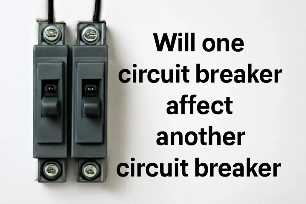
You might see one circuit breaker impact another. This usually happens because of shared wiring or panel problems. For example, some circuits share a neutral wire, like in MWBC. If one circuit has an issue, it can mess up the other. To check, see if the breakers are connected and follow the wires. Look for two hot wires sharing one neutral wire. These cases make it seem like circuit breaker impact occurs between breakers, but they work separately.
Key Takeaways
- Circuit breakers keep your home safe by stopping too much electricity. They can be reset and used again, unlike fuses.
- Shared neutral wires in circuits can be confusing. If one trips, it might affect another because of shared wiring.
- Too many devices on one circuit can trip breakers. Use different circuits for high-power devices to avoid overloads.
- Check your electrical panel often for loose wires or damage. This prevents problems and keeps your system working well.
- Call an electrician if breakers trip often, you smell burning, or have questions. Experts make sure everything is safe and follows rules.
Understanding Circuit Breaker Independence
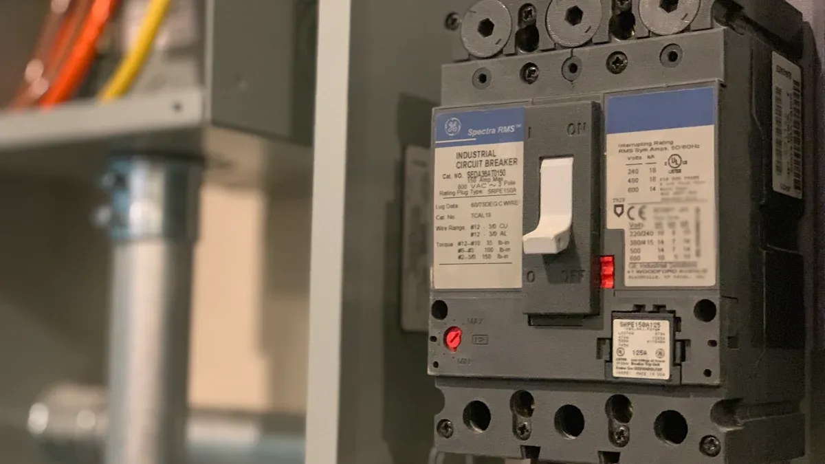
The purpose and function of circuit breakers
Circuit breakers protect your home’s electrical system from harm. They stop too much electricity, called overcurrent, from flowing. When this happens, the breaker shuts off the power to prevent fires or damage. Unlike fuses, which must be replaced, breakers can be reset and used again. This makes them a safe and easy-to-use tool.
There are different types of circuit breakers for various problems. Magnetic breakers stop sudden power surges. Thermal breakers shut off when wires get too hot. These devices keep your home’s electricity running safely.
Why circuit breakers are designed to operate independently
Circuit breakers are made to work alone to protect specific circuits. Each breaker watches its own circuit and trips if there’s a problem, like too much power or a short. This design stops one issue from affecting the whole system.
Rules like UL 489 make sure breakers are safe and work well. Breakers are built to stop power during problems without needing help from others. These features protect your wires and devices.
- Breakers stop power during overloads or other issues.
- They follow strict rules to stay safe and reliable.
- Each breaker works alone to avoid system-wide problems.
Common misconceptions about circuit breaker impact
Some think one breaker can make another trip, but that’s not true. Breakers are made to work separately. However, shared wires, like neutral wires in MWBC, can make it seem like they affect each other. Overloaded circuits or heat from nearby breakers can also confuse people.
Knowing these situations helps you find the real problem. Usually, breaker issues come from outside factors, not the breakers themselves.
| Test Type | What It Checks |
|---|---|
| Short-Circuit Testing | Makes sure breakers handle high power safely in certain cases. |
| Type Tests | Tests like endurance, heat, and voltage to check performance. |
| Environmental Testing | Checks outdoor breakers in different weather conditions. |
By understanding these myths, you can fix problems better and keep your system safe.
Scenarios of Circuit Breaker Impact
Shared neutral wires and their effect on breaker behavior
Shared neutral wires, common in multi-wire branch circuits (MWBC), can confuse troubleshooting. In these setups, two hot wires use one neutral wire. This saves space but may cause problems. If one circuit trips, the shared neutral might affect the other circuit.
You may see flickering lights or devices not working. These signs often mean the shared neutral is unbalanced. When one breaker trips, the neutral wire might carry extra current. This can make it seem like one breaker affects another, even though they work separately.
Tip: To spot shared neutral wires, check for two breakers with a handle tie or two hot wires using one neutral wire. If unsure, ask a licensed electrician for help.
Overloaded circuits and multiple breaker trips
Overloaded circuits happen when too many devices use one circuit. This makes the breaker trip to stop overheating. Sometimes, an overloaded circuit causes nearby breakers to trip too.
This happens because the panel spreads power across circuits. One overloaded circuit can create a temporary imbalance. This imbalance might make nearby breakers trip as a safety step. It looks like breakers are affecting each other, but it’s the panel protecting your home.
To prevent this, spread out your electrical load. Plug big devices, like heaters, into different circuits. This lowers the chance of overloading and keeps breakers working properly.
Heat transfer between close breakers
Heat transfer between breakers can also seem like interaction. Breakers close together in a panel can get warm during use. If one breaker gets too hot, it might heat nearby breakers. This extra heat can make other breakers trip, even if their circuits are fine.
You can stop this by keeping good airflow around your panel. Don’t put the panel in places with bad ventilation or high heat. Regular checks, like tightening connections, can also help avoid heat problems.
Note: If heat causes frequent trips, think about upgrading your panel or replacing old breakers with newer ones.
Electrical panel problems, like loose connections or damaged bus bars
Electrical panel problems often come from loose connections or damaged bus bars. These issues can mess up your electrical system and cause safety risks. Knowing how they happen and what they can do helps you fix them.
Loose connections happen when wires or breakers don’t stay attached well. Over time, some materials, like aluminum wiring, wear out faster than copper. This wear makes connections weaker, which can lead to overheating or sparks. For example:
- Aluminum wires expand and shrink with heat, loosening their grip on the bus bar.
- Breakers might look fine but lose their tight connection, causing random electrical problems.
Damaged bus bars also cause trouble in panels. The bus bar sends power to breakers, so any damage can affect several circuits. Wiring mistakes are a common problem. For example, a dryer circuit might be wired wrong, putting the bare wire on the ground bus instead of the neutral. This mistake can lead to serious problems, like:
- The dryer breaker sticking to the bus bar on one side.
- Heat damage spreading through the wire back to the main panel.
These examples show how loose connections and bad bus bars can seem like breaker issues. You might see breakers trip or circuits act strangely. But the real problem is usually in the panel, not the breakers.
To avoid these problems, check your electrical panel often. Look for signs like burn marks, loose parts, or discoloration. If you think something’s wrong, don’t try to fix it yourself. Call a licensed electrician to safely handle the issue.
Tip: Older panels with aluminum parts are more likely to have loose connections. Switching to newer materials can make your system safer and more reliable.
Troubleshooting Circuit Breaker Issues
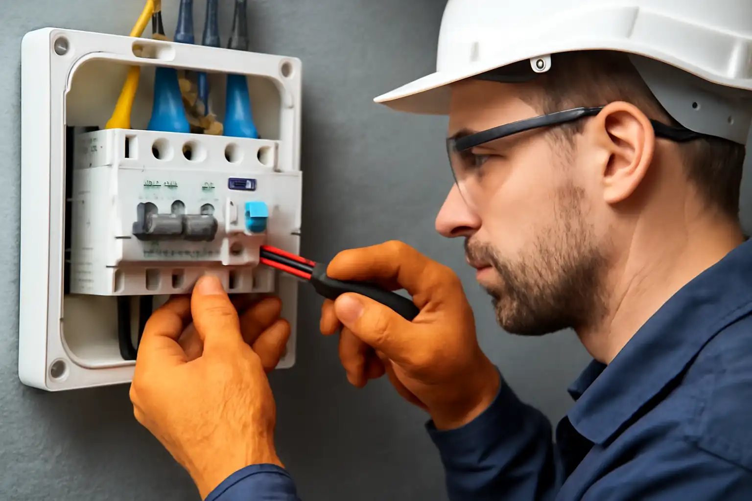
Finding shared circuits and neutral wires
Shared circuits and neutral wires can make fixing problems tricky. Knowing how to spot these setups helps you understand their effects on breakers. Multi-wire branch circuits (MWBC) are a common example. In these, two hot wires share one neutral wire. This saves space but may cause unbalanced currents or unexpected trips.
Here’s how to find shared circuits and neutral wires:
| Method | What to Do |
|---|---|
| Voltage Testing | Use a tester. Live wires have full voltage; neutral wires don’t. |
| Outlet Position | Check outlet slots. Neutral wires connect to the wider slot. |
| Polarity Testing | Use a tester to confirm wire types. Live wires show positive; neutral wires show negative. |
| Common Problems | Look for loose wires, overloading, open circuits, or wrong wire sizes. |
Tip: Suspect shared neutral wires? Look for breakers with handle ties or two hot wires sharing one neutral. If unsure, ask an electrician for help.
Checking the electrical panel for damage or wear
Your electrical panel spreads power through your home. Damage or wear in the panel can cause breaker trips or other issues. Regular checks help you find problems early and keep things safe.
Follow these steps to inspect your panel:
- Look at past service records for your equipment.
- Check inspection logs and testing notes.
- Study incident reports to find patterns.
Use this table to plan your inspections:
| How Often | Type of Check | What to Look For |
|---|---|---|
| Daily | Quick Look | Spot hazards like exposed wires or overheated parts. |
| Weekly | Basic Checks | Make sure everything is working as it should. |
| Monthly | Detailed Checks | Use thermal imaging and tests to find hidden problems. |
| Annually | Full Inspection | Do deep testing to ensure long-term safety. |
Note: Keep records of all checks and fixes. These help you track your system’s condition and follow safety rules.
Spotting heat-related breaker trips
Heat-related trips often mean deeper electrical problems. You can find these by watching for certain signs and knowing their causes.
Signs of heat problems include:
- Sparks or burn marks near outlets.
- A burning smell around appliances or outlets.
- Buzzing or popping sounds from switches or outlets.
- A tingling feeling when touching appliances.
- Breakers tripping often or fuses blowing.
- Lights flickering or not turning off fully.
Heat-related trips are often caused by bad wiring, loose connections, or overloaded circuits. These problems make things overheat, which trips the breaker to keep you safe.
Alert: If you see these signs, act fast to avoid more damage. Don’t try to fix heat problems yourself. Call an electrician to handle repairs safely.
When to call a licensed electrician for professional help
Knowing when to call an electrician can keep you safe. Some small tasks, like resetting a breaker, seem easy. But bigger problems need expert help. Licensed electricians are trained to fix tough issues safely. They also make sure your system follows safety rules.
Here are times to call an electrician:
- Frequent breaker trips or unexplained power outages: Breakers that trip often or random power loss may mean deeper problems. These could be overloaded circuits, bad wiring, or broken parts.
- Burning smells or scorch marks: A burning smell near outlets or switches means overheating. Scorch marks on wires or outlets need quick attention.
- Flickering or dimming lights: Lights that flicker or dim when using appliances may mean loose connections or overloaded circuits. These problems can get worse if ignored.
- Upgrading or installing new electrical systems: Adding circuits, upgrading panels, or installing big appliances needs careful work to meet safety rules.
- Older homes with outdated wiring: Old wiring, like aluminum or knob-and-tube systems, may not be safe. Electricians can check and update these systems to prevent risks.
Tip: If you’re unsure about a problem, call an electrician. Electrical issues can become dangerous quickly.
Electricians follow strict safety rules and know the latest codes. Their training helps them fix problems the right way. Hiring a licensed electrician ensures safe and proper repairs. This lowers the chance of accidents or future issues.
Trying to fix electrical problems yourself can be risky. You might cause shocks, fires, or more damage. Always call a professional for serious or ongoing electrical issues.
Preventing Circuit Breaker Impact
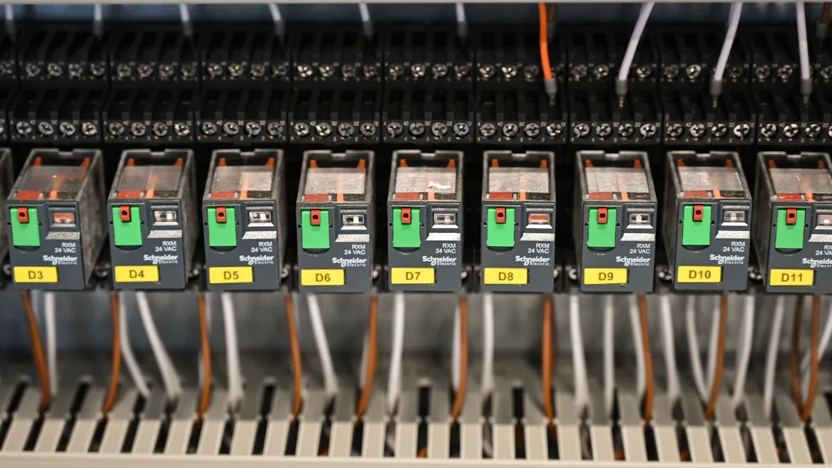
Labeling circuits and breakers correctly
Labeling circuits and breakers helps you find problems quickly. Each breaker needs a clear label showing what it controls. For example, labels like “Kitchen Outlets” or “Living Room Lights” make it easy to locate the right breaker during repairs or emergencies. Following rules ensures your labels are useful and meet safety standards.
| Standard | What It Requires |
|---|---|
| NEC 110.22 | Every breaker must have a clear label for its purpose. |
| NFPA 70, Article 408.4 | Labels must be easy to read and understand. |
Tip: Use permanent markers or printed labels so they last longer. Check and update labels if circuits change.
Keeping loads balanced across circuits
Balancing power across circuits stops overloads and prevents tripped breakers. Uneven power use can overwork some circuits, causing overheating or failure. To avoid this, spread out high-power devices like heaters and air conditioners on different circuits. A balanced system works better in larger setups.
- Assign devices to circuits based on their power needs.
- Mix different types of loads for better performance.
- Adjust transformers or feeders to fix load imbalance.
Studies show balancing loads lowers electrical problems. For example, one study reduced imbalance from 30.86% to 5.59% using proper methods. IEEE standards suggest keeping imbalance under 20%.
Note: Check your system’s load balance often, especially during busy times, to keep it safe.
Inspecting and maintaining the electrical panel regularly
Regular checks of your electrical panel prevent fires and failures. Inspections find loose parts, damage, or wear before they cause trouble. High-voltage breakers need checks every 6–12 months. Medium-voltage breakers should be checked yearly or after 2,000 uses.
- Use tools like infrared thermography to spot overheating.
- Watch for temperature and humidity changes that affect breakers.
- Follow the manufacturer’s instructions for safe and reliable maintenance.
Alert: Skipping maintenance can lead to expensive repairs or dangers. Always inspect your system to keep it safe and working well.
Upgrading old or broken electrical parts
Old or broken electrical parts can be dangerous at home or work. Older circuit breakers may not have today’s safety features. This makes them less effective at stopping electrical problems. Upgrading these parts helps your system work better and meet safety rules.
New circuit breakers are safer and more reliable than old ones. They have better safety features to prevent accidents and protect your devices. For example, newer breakers work faster to stop faults and keep your equipment safe. They also help you spot problems early with predictive maintenance.
Tip: If your home has an old panel or aluminum wiring, think about upgrading to newer materials. This can make your system much safer and more reliable.
Here’s a simple table showing why upgrading helps:
| Factor | What It Does |
|---|---|
| Reliability | New breakers work better and help find problems early. |
| Functionality | Faster response times protect your devices from damage. |
| Safety | Following updated safety rules keeps everyone safer. |
Upgrading also helps you follow safety rules like NFPA 70E and NFPA 70B. These rules are important for keeping homes and workplaces safe. Modern systems are easier to maintain and test, making them more reliable.
- Why upgrade?
- New safety features lower the chance of accidents.
- Maintenance is easier and quicker.
- Following safety rules improves overall protection.
Note: Ignoring old parts can cause frequent trips, overheating, or even fires. Upgrading prevents these risks and keeps your system safe.
By switching to modern electrical parts, you protect your home and ensure everything works well for years. Regular checks and timely upgrades keep your system safe and efficient.
Circuit breakers are made to work alone, keeping circuits separate. But shared wires, panel problems, or heat can seem like they connect. A 10-year study on circuit breakers proved they work independently. It used data to show that these issues don’t harm their performance.
Fixing these problems fast keeps your home safe. Regular checks, spreading out power use, and upgrading old parts improve safety. For tough or ongoing issues, call a licensed electrician. They can fix problems correctly and give you peace of mind.
FAQ
Why does a circuit breaker keep tripping?
Breakers trip often due to too much power use, wiring issues, or faulty devices. Overloading happens when many devices use one circuit. Damaged wires or bad appliances can cause short circuits or ground faults. Fixing the main problem stops the trips.
How are shared and dedicated neutrals different?
Shared neutrals are in circuits where two hot wires use one neutral. Dedicated neutrals only serve one circuit. Shared neutrals save space but might cause uneven power. Dedicated neutrals lower the chance of problems between circuits.
What should you do if a breaker feels hot?
A hot breaker means overheating from loose wires, too much power, or damage. Turn it off right away and stop using the circuit. Call an electrician to check and fix it to stay safe.
What happens if you ignore a breaker that trips a lot?
Ignoring frequent trips can cause fires or damage devices. Breakers trip to protect your home from electrical problems. Fixing the issue quickly keeps your system safe and working well.
What tools help find problems in an electrical panel?
Tools like voltage testers, heat cameras, and polarity testers are useful. Voltage testers check live wires, heat cameras find hot spots, and polarity testers check wiring. These tools make finding and fixing problems easier and safer.
The following information may be of interest to you
What Causes Circuit Breaker Overheating and How to Prevent It
Comprehensive guide for wiring methods of air circuit breakers
How to Resolve RCCB Tripping Problems at Home
What Are the Key Differences Between 3-Pole and 4-Pole Circuit Breakers

Discover more from SENTOP Electrical Co., Ltd
Subscribe to get the latest posts sent to your email.
