
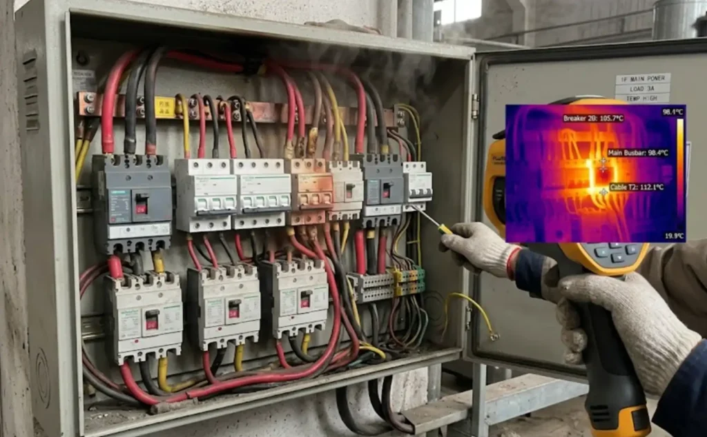
A standard circuit breaker rated at 100A doesn’t actually deliver 100A when ambient temperature climbs above 40°C — it might only handle 80A safely before nuisance tripping or, worse, failing to protect the circuit at all. Circuit breaker derating factors for temperature quantify exactly how much you need to reduce a breaker’s rated current as the surrounding environment heats up, and ignoring them is one of the most common causes of unexplained trips in industrial panels and rooftop equipment. This guide breaks down manufacturer derating tables, NEC and IEC correction requirements, and step-by-step calculations so you can size breakers correctly for any ambient condition.
What Is Circuit Breaker Temperature Derating and Why It Matters
Every circuit breaker ships with a current rating — say 20A, 50A, or 100A — but that number only holds true at a specific ambient temperature. For most manufacturers, the calibration baseline is 40°C (104°F). Push the surrounding air temperature above that threshold, and the breaker’s actual safe carrying capacity drops. This reduction is called temperature derating.
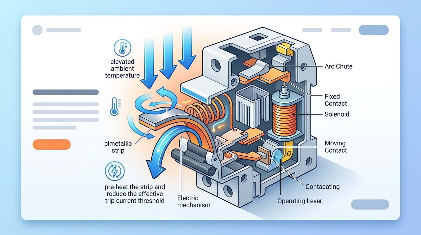
Why does this happen? The thermal-magnetic trip element inside the breaker relies on a bimetallic strip that bends when heated. Higher ambient temperatures pre-heat that strip, meaning it reaches its trip point at a lower current than the nameplate suggests. A 20A breaker in a 60°C enclosure might only handle 16A before tripping.
Ignoring circuit breaker derating factors for temperature doesn’t just cause nuisance trips — it creates a cascade of reliability and safety problems that cost real money and risk real harm.
The consequences break down into three categories:
- Nuisance tripping: Breakers trip under normal load, shutting down critical equipment and causing unplanned downtime — a single event in an industrial facility can cost $5,000–$50,000+.
- Premature breaker failure: Sustained operation near thermal limits degrades internal contacts and insulation, cutting the breaker’s service life by 30–50% according to data published by Schneider Electric and Eaton.
- Fire hazards: A breaker that fails to trip at the correct threshold allows conductors to overheat, violating NEC Article 240 protection requirements and dramatically increasing fire risk.
Temperature derating isn’t optional engineering finesse — it’s a fundamental safety calculation. If your panel sits in a rooftop mechanical room, a southern-facing electrical closet, or next to heat-generating equipment, the ambient temperature almost certainly exceeds 40°C for significant portions of the year. Skipping the math means gambling with protection coordination across your entire system.
How Thermal-Magnetic Trip Mechanisms Respond to Ambient Heat
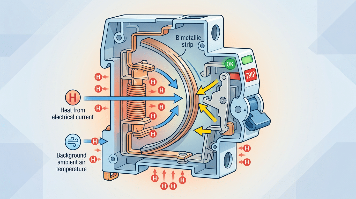
Inside every thermal-magnetic breaker sits a bimetallic strip — two metals with different thermal expansion coefficients bonded together. As current flows, resistive heating bends the strip until it triggers the trip mechanism. Here’s the problem: that strip doesn’t distinguish between heat generated by current and heat absorbed from the surrounding air.
Manufacturers calibrate trip curves at a reference ambient of 40°C (per IEC 60947-2 and UL 489 standards). Place that same breaker in a 60°C enclosure, and the bimetallic strip starts with a 20°C “head start.” The strip needs far less current-generated heat to reach its deflection threshold, so it trips at roughly 80–85% of its rated current. This is the core reason circuit breaker derating factors for temperature exist — the physics of bimetallic deflection makes it unavoidable.
A Schneider Electric technical note on Compact NSX breakers confirms that a 20°C rise above calibration temperature can reduce effective trip current by 10–20%, depending on frame size.
Electronic trip units handle this differently. Microprocessor-based breakers from manufacturers like ABB’s Emax series and Eaton’s Digitrip use current transformers to measure load directly, with built-in algorithms that compensate for ambient temperature shifts. They don’t rely on physical deflection, so their trip accuracy stays consistent from 0°C to 70°C. The trade-off? They cost 3–5× more than equivalent thermal-magnetic units.
If your installation runs hot and budget allows, electronic trip units eliminate the temperature derating problem entirely. For thermal-magnetic breakers — which still dominate in residential and light commercial panels — understanding and applying derating is non-negotiable.
Standard Derating Tables by Manufacturer
Not all breakers derate identically. Eaton, ABB, Schneider Electric, and Siemens each publish their own correction factors for molded-case circuit breakers (MCCBs), and the differences can surprise you — especially above 50°C ambient.
The table below compiles typical derating multipliers for a 100A-frame MCCB across these four manufacturers. Values represent the percentage of rated current available at each ambient temperature.
| Ambient Temp | Eaton | ABB | Schneider Electric | Siemens |
|---|---|---|---|---|
| 25°C | 100% | 100% | 100% | 100% |
| 30°C | 100% | 100% | 100% | 100% |
| 40°C | 100% | 97% | 100% | 100% |
| 50°C | 92% | 90% | 93% | 91% |
| 55°C | 88% | 86% | 89% | 87% |
| 60°C | 83% | 82% | 85% | 83% |
| 65°C | 78% | 77% | 80% | 78% |
Always verify against the specific product datasheet. The values above reflect general catalog data for standard thermal-magnetic MCCBs — electronic-trip breakers follow different curves entirely.
Notice ABB’s slightly more aggressive derating at 50°C (90%) versus Schneider’s more conservative 93%. A 3-point gap on a 100A breaker means 3 amps of usable capacity — enough to matter in a tightly loaded panel. These circuit breaker derating factors temperature tables are the single most important reference when sizing protection in high-heat environments.
Each manufacturer publishes these tables in their technical catalogs: Eaton’s Bussmann division handbook, ABB’s SACE Tmax series documentation, Schneider’s Compact NSX guides, and Siemens’s SENTRON 3VA datasheets. Pull the exact model-specific table before finalizing any design.
How to Read and Apply a Manufacturer Derating Table
A derating table looks straightforward — rows, columns, numbers — but misreading a single cell can mean specifying a breaker that nuisance-trips or, worse, one that fails to protect downstream conductors. Here’s how to decode one correctly.
Anatomy of a Typical Derating Table
Most tables published by Eaton, Schneider Electric, or ABB share a common layout:
- Left column: Frame size or rated current (e.g., 15A, 20A, 60A, 100A).
- Top row: Ambient temperature in °C — usually spanning 25°C to 70°C in 5° increments.
- Cell values: The derated ampacity, expressed either as a percentage multiplier (e.g., 0.82) or as an absolute ampere value.
Footnotes matter more than most engineers realize. A footnote might specify that the table assumes open-air mounting, a single breaker per enclosure, or calibration at 40°C rather than the older 25°C standard. Miss that detail and your circuit breaker derating factors temperature lookup is wrong from the start.
Matching Your Conditions to the Right Value
Start with the breaker’s frame size — not the trip unit setting. A 100A frame with a 70A trip still derates based on the 100A frame row. Next, identify your actual ambient temperature inside the panel, not the room temperature. Enclosure air can run 10–15°C hotter than the surrounding space.
If your ambient falls between two listed temperatures, always round up to the next higher value. Interpolating between columns is acceptable in engineering analysis, but for field work, conservative rounding prevents callbacks. Cross-reference the cell value against your load calculation, and you have your derated capacity — the true safe operating current for that specific installation condition.
NEC vs IEC Temperature Correction Factor Requirements
The single biggest difference? Calibration baseline. NEC (NFPA 70) assumes breakers are tested and calibrated at 40°C ambient, while IEC 60947-2 uses the same 40°C reference but requires manufacturers to verify performance across a defined temperature range — typically −5°C to +40°C for standard duty. That 40°C figure sounds identical, yet the compliance paths diverge sharply from there.
Under NEC Article 240, breakers must carry 100% of their rated current at 40°C unless listed as “100% rated” devices (which are calibrated at the full nameplate load). Most standard breakers are actually calibrated to trip at 80% of their continuous rating. IEC 60947-2, by contrast, mandates that manufacturers publish utilization categories (AC-1 through AC-4) and provide explicit circuit breaker derating factors temperature correction data within the product’s technical documentation.
| Criteria | NEC (NFPA 70) | IEC 60947-2 |
|---|---|---|
| Calibration Baseline | 40°C | 40°C |
| Continuous Load Rule | 80% unless 100%-rated | Defined by utilization category |
| Correction Factor Source | Manufacturer tables | Mandatory in product documentation |
| Jurisdiction | United States, Canada (with CSA harmonization) | Europe, Asia, most international markets |
Jurisdiction determines everything. A panel designed for export to Germany needs IEC-compliant breakers with documented temperature correction factors — NEC-listed devices won’t satisfy CE marking requirements. When evaluating circuit breaker derating factors for temperature in multi-market projects, always confirm which standard governs before selecting hardware. Mixing frameworks leads to rejected inspections and costly redesigns.
Step-by-Step Calculation of Derated Breaker Capacity
Here’s the core formula you need:
Derated Current = Rated Current × Derating Factor
Simple enough. The real work is pulling the correct derating factor from the manufacturer’s table and applying it without rounding errors. Walk through this with a concrete example.
Worked Example: 60A Breaker at 50°C
Assume you’re specifying a Siemens 60A thermal-magnetic breaker (calibrated at 40°C per IEC 60947-2). The panel sits in a mechanical room where ambient temperature holds steady at 50°C. Siemens publishes a derating factor of 0.90 for this 10°C elevation above baseline.
- Identify rated current: 60A at 40°C reference
- Find the derating factor: 0.90 (from the Siemens derating table for 50°C ambient)
- Calculate: 60A × 0.90 = 54A effective continuous capacity
That 6A reduction matters. If your actual continuous load is 57A, this 60A breaker no longer has adequate margin — you’d need to upsize to a 70A or 80A frame, or reduce the ambient temperature mechanically.
How This Affects Conductor Sizing
The derated breaker capacity directly governs your wire gauge selection per NEC Table 310.16. A 54A effective rating means your conductors must handle at least 54A at the same elevated temperature, requiring their own separate temperature correction. Ignoring circuit breaker derating factors temperature adjustments at this stage is where undersized conductors and nuisance trips originate.
Sample Calculation for a 100A Breaker at 55°C Ambient
Picture a steel mill’s motor control center. The ambient temperature inside the panel hovers at 55°C — common in foundries, boiler rooms, and outdoor enclosures in desert climates. You’ve specified a 100A thermal-magnetic breaker. What’s the actual safe current capacity?
Grab the manufacturer’s derating table. For a typical Eaton or ABB molded-case breaker calibrated at 40°C, the derating factor at 55°C falls around 0.82. Apply the formula:
Derated Current = 100A × 0.82 = 82A
That 100A breaker now handles only 82A before the bimetallic strip trips. Your circuit’s full-load current of 95A? It will cause nuisance tripping — guaranteed.
Design Decisions That Follow
You have two paths. Upsize to a 125A frame, which at the same 0.82 factor yields 102.5A of usable capacity — enough headroom for the 95A load. Alternatively, improve ventilation or install forced-air cooling to pull the enclosure temperature back toward 40°C, preserving the original 100A rating.
Cost matters here. A frame upsize typically runs $40–$120 more per breaker, while panel ventilation fans cost $150–$300 but protect every device inside. For a single breaker, upsizing wins. For a fully loaded panel in a hot environment, cooling the enclosure is the smarter investment.
This example shows exactly why understanding circuit breaker derating factors temperature relationships prevents costly field failures. Never assume the nameplate number is the number you can use — the ambient environment always has the final say.
Derating Factors for Breakers Installed in Enclosed Panels
A breaker’s nameplate rating assumes open-air mounting at 40°C. Bolt that same breaker inside a sealed panel packed with other heat-generating devices, and the actual air surrounding it can climb 15–25°C above the room’s ambient temperature. That gap is where most engineers underestimate risk.
How hot does it really get? NEMA 1 general-purpose enclosures with moderate component density typically see a 10–15°C internal rise above external ambient. NEMA 4 watertight enclosures — sealed against dust and water ingress with no passive ventilation — push that rise to 20–30°C. A 35°C equipment room plus a 25°C enclosure rise means your breakers are operating at 60°C, well past the standard calibration baseline.
Stack the derating: first apply the enclosure temperature rise to determine true internal ambient, then use the manufacturer’s derating table for that temperature. These are multiplicative penalties, not alternatives.
Grouping matters enormously. Three breakers carrying 80% load side by side generate far more mutual heating than a single breaker at the same load. Schneider Electric’s Prisma technical guides document an additional 5–10% current reduction when more than six breakers share a single compartment without forced ventilation. ABB’s installation manuals for Tmax series breakers include similar grouping correction tables.
Practical fixes that reduce enclosure temperature rise:
- Forced ventilation fans with filtered inlets — can cut internal rise by 40–60%
- Thermostatically controlled exhaust vents on NEMA 1 panels
- Spacing breakers at least 25 mm apart to limit thermal coupling
- Using oversized enclosures to increase internal air volume
Ignoring enclosure effects is the fastest way to miscalculate circuit breaker derating factors temperature corrections. The breaker doesn’t know what the room thermostat reads — it only feels the air directly around its bimetallic element. Design for the temperature inside the panel, not outside it.
When to Upsize a Breaker vs When to Reduce Ambient Temperature
You’ve run the derating calculation and your breaker can’t carry the load. Now what? Two paths diverge: install a larger-frame breaker or cool the environment. The right choice depends on cost, code compliance, and how that change ripples through your protective coordination study.
Upsizing the Breaker Frame
Jumping from a 100A to a 150A frame is the fastest fix — often under $200 in material cost for molded-case breakers. But a larger breaker demands re-evaluation of downstream conductor sizing per NEC 240.4 and upstream short-circuit ratings. Your existing coordination study may no longer hold, meaning time-current curves shift and selective coordination with downstream devices breaks down. Budget $1,500–$4,000 for an engineer to redo that study.
Reducing Ambient Temperature Instead
Adding forced ventilation fans ($50–$300 per panel) or relocating the enclosure away from heat sources can bring ambient conditions back toward the 40°C calibration baseline. This approach preserves your existing circuit breaker derating factors temperature calculations and avoids coordination headaches entirely. For outdoor installations in hot climates, shade structures or reflective panel coatings deliver 8–12°C reductions at minimal cost.
Electronically-Tripped Breakers: The Third Option
Electronic trip units aren’t affected by ambient heat the same way bimetallic strips are — their current-sensing CTs and microprocessors maintain accuracy across a wider temperature range. Schneider Electric’s Micrologic and Eaton’s Digitrip units, for example, hold rated performance up to 70°C. The upfront premium is 30–50% over thermal-magnetic equivalents, but you eliminate the entire circuit breaker derating factors temperature problem at the source.
Rule of thumb: if the ambient exceeds 50°C and you’re managing more than three circuits, electronic trip breakers pay for themselves within two panel redesign cycles.
Common Mistakes Engineers Make With Temperature Derating
Even experienced engineers stumble on derating. Here are the most costly errors — and how to fix each one.
Mistake 1: Using Conductor Derating Instead of Breaker-Specific Factors
NEC Table 310.15(B)(1) provides temperature correction factors for conductors, not breakers. Applying a 25°C-based wire correction factor to a breaker calibrated at 40°C will overstate the available capacity. Always pull the derating curve from the breaker manufacturer’s datasheet — Eaton, ABB, and Schneider each publish device-specific tables that differ from conductor tables.
Mistake 2: Ignoring Enclosure Heat Rise
Treating the room’s ambient as the breaker’s ambient is dangerously optimistic. Internal panel temperatures routinely run 10–15°C above the surrounding air. Measure inside the enclosure at the breaker’s mounting location, then apply the correct circuit breaker derating factors temperature data to that measured value — not the room thermostat reading.
Mistake 3: Assuming Electronic Trip Units Are Immune
Electronic trip units use current transformers and microprocessors instead of bimetallic strips, so many engineers skip derating entirely. Wrong. Current sensors and semiconductor components still drift at extreme temperatures. Schneider Electric’s Micrologic trip units, for example, specify reduced accuracy above 70°C. Check the trip unit’s operating range separately from the breaker frame rating.
Mistake 4: Forgetting Altitude Effects
Above 2,000 meters, thinner air reduces convective cooling. IEC 60947-2 requires an additional 1% derating per 500 m beyond that threshold. A breaker at 50°C ambient and 3,000 m altitude needs both corrections applied multiplicatively — not just one.
Best practice: build a checklist — ambient source, enclosure rise, trip technology, and altitude — before selecting any circuit breaker derating factors for temperature-sensitive installations.
Frequently Asked Questions About Circuit Breaker Temperature Derating
At what temperature do you start derating a circuit breaker? That depends on the calibration standard. NEC-rated breakers are calibrated at 40°C, so derating kicks in above that threshold. IEC breakers (per IEC 60947-2) also use 40°C as the reference ambient. Below 40°C, most manufacturers actually allow a modest uprating — but always verify with the specific datasheet.
Do MCBs derate differently than MCCBs? Yes. Miniature circuit breakers (MCBs) are physically smaller, dissipate heat less efficiently, and typically derate more aggressively per degree above 40°C. A typical MCB might lose 1.5–2% of its rating per °C, while a larger molded-case circuit breaker (MCCB) might lose closer to 1%.
Does altitude affect derating? Absolutely. Above 2,000 meters, thinner air reduces convective cooling. IEC 60947-1 recommends an additional correction — roughly 1% derating per 500 meters above 2,000m. This stacks on top of any circuit breaker derating factors temperature adjustments you’ve already applied.
Can you use one manufacturer’s derating factor on another’s breaker? No. Trip curve geometry, bimetal composition, and housing materials differ between Eaton, ABB, and Schneider. Always use the OEM’s published table.
Is the 80% rule the same as temperature derating? They overlap but aren’t identical. NEC Article 210.20 limits continuous loads to 80% of the breaker’s rating — a load restriction, not a thermal correction. Temperature derating reduces the breaker’s effective trip threshold itself. In hot environments, both apply simultaneously, compounding the capacity reduction.
Key Takeaways and Actionable Summary
Three things determine whether your breaker performs safely or trips unpredictably: the manufacturer’s calibration temperature, the actual ambient conditions, and the enclosure heat rise stacked on top. Miss any one of these, and your protection scheme has a blind spot.
Core rule: Always multiply the breaker’s nameplate rating by the correct derating factor before you finalize conductor sizing. A 100A breaker at 55°C ambient may only deliver 80A of reliable capacity — and your wire gauge must match the derated value, not the stamped number.
Here’s your quick-reference checklist:
- Confirm the baseline. NEC-rated breakers assume 40°C; IEC-rated units assume 40°C or sometimes 35°C. Never guess — pull the actual datasheet.
- Apply circuit breaker derating factors for temperature from the specific manufacturer’s table, not a generic chart found online.
- Add enclosure penalties. Sealed NEMA 4X panels can push internal temperatures 10–15°C above ambient, compounding the derating you already calculated.
- Document everything. Record the ambient temperature assumption, derating factor used, and final derated current in your panel schedule for future audits.
Bookmark the Eaton, ABB, and Schneider Electric derating tables referenced earlier in this guide — they update periodically, so check for the latest revision at least annually. If your installation faces jurisdiction-specific amendments to NEC Article 240 or IEC 60947-2, contact your local Authority Having Jurisdiction (AHJ) before procurement.
Proper derating costs nothing but a few minutes of calculation. Skipping it costs downtime, damaged equipment, and potentially lives.
See also
Circuit Breaker Derating: How Ambient Temperature Affects Sizing
How to Interpret Terminal Block Markings for UL/IEC Panels
How Customized RCCBs Provide Solutions for Temperature Fluctuations
3 ways environmental temperature changes circuit breaker performance
A Step-by-Step Guide to NEMA Enclosure Ratings and Common Mistakes

Discover more from SENTOP Electrical Co., Ltd
Subscribe to get the latest posts sent to your email.
