
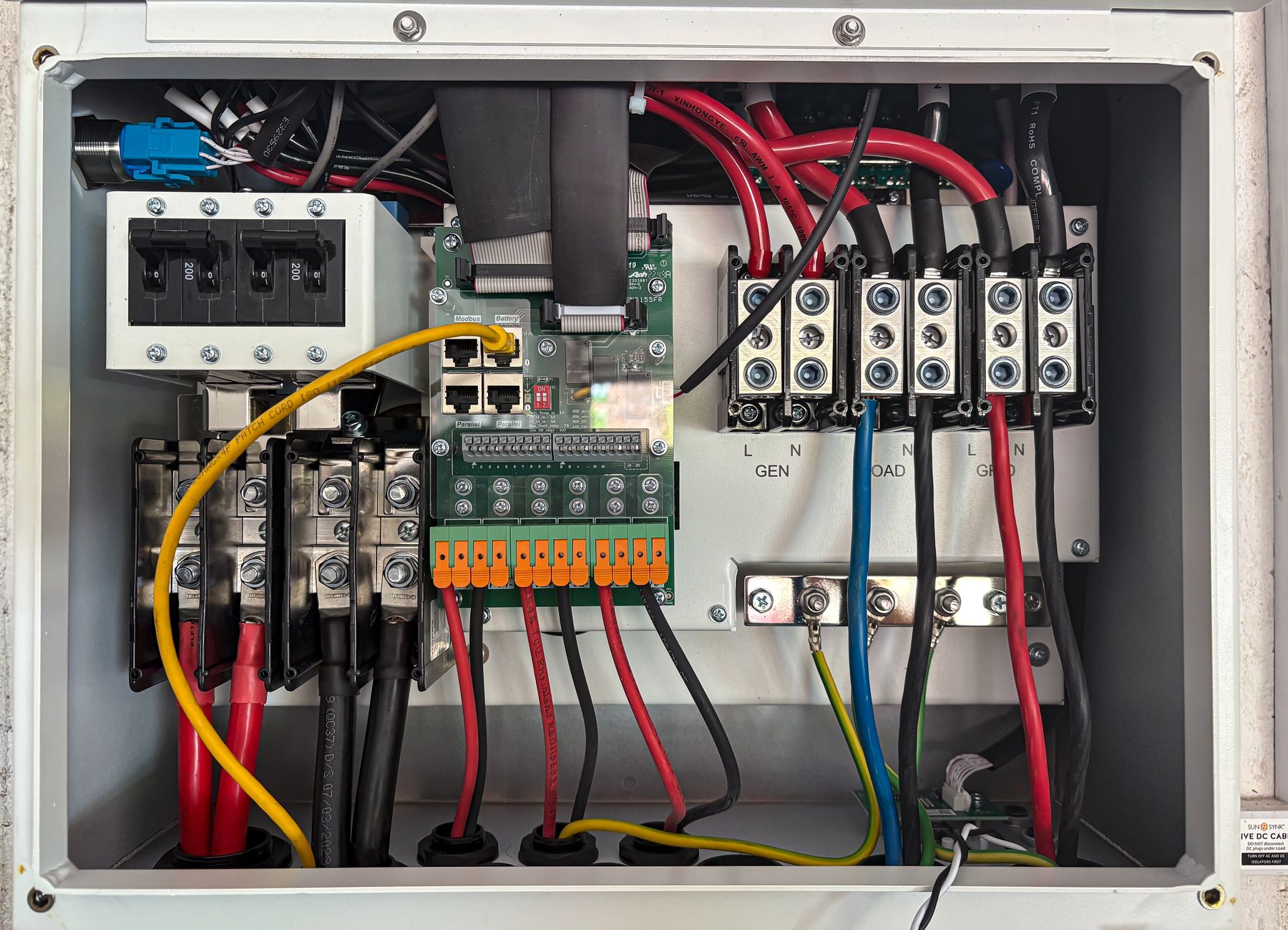
Control Cabinet Wiring Components for Organized Panel Building
A dependable control cabinet wiring system is more than a list of parts. It coordinates DIN rail mounting, wire routing, terminal interfaces, PE connections, power distribution, marking, bridging and documentation around the actual circuits. SENTOP helps panel builders and OEM buyers convert drawings and field requirements into a reviewable terminal-strip and accessory BOM.
What are control cabinet wiring components?
Control cabinet wiring components are the parts that mount, route, terminate, identify, distribute and protect conductors inside an electrical panel. The core system usually includes DIN rail, wiring duct, terminal blocks, end clamps, end plates, bridges, markers, PE terminals and conductor identification. Depending on the panel, it may also coordinate power supplies, protection devices, relays, contactors, PLC or I/O modules, interface devices and digital meters.
The correct set cannot be selected from cabinet size alone. Buyers should confirm the electrical drawings, circuit functions, conductor data, terminal count, short-circuit and protection concept, environmental conditions, target-market requirements, maintenance method and future expansion plan before freezing the BOM.
Mount and route
DIN rail, mounting hardware and wiring duct create the physical structure that keeps components and conductors accessible.
Terminate and distribute
Feed-through, PE, multi-level, disconnect, distribution and pluggable terminals organize field and internal connections.
Identify and document
Terminal markers, wire labels, device tags and drawings help installation, commissioning and maintenance teams trace every circuit.
Bond and verify
PE and shield arrangements, protective devices and final verification must match the panel design and applicable project standards.
Organize the cabinet by electrical function
A practical layout starts with circuit groups and maintenance access. Select a zone below to see what typically belongs there and which project data must be confirmed.
Layout note: This diagram is a functional planning aid, not an engineering drawing. Required separation, conductor routing, protective bonding, heat management, clearances and verification depend on the exact panel, component documentation and applicable standards.

Build the field interface around circuit function
A control cabinet terminal strip is the boundary between field cables and internal panel wiring. Organizing positions by function makes installation and fault tracing easier than mixing circuits only by cable order.
Select each component from the data it must handle
This matrix helps turn a schematic, terminal plan and enclosure layout into a procurement checklist. Final model selection still requires the exact manufacturer data and project rules.
| Function | Typical component | Data to confirm | Why it matters |
|---|---|---|---|
| Mounting | DIN rail, mounting plate, end clamps and mounting hardware | Rail profile, component system, load, enclosure material, fixing points and available length | Provides stable component positioning and keeps the assembly compatible with the chosen terminal and device families. |
| Wire routing | Wiring duct, covers, separators, cable ties and cable-entry accessories | Wire quantity, conductor outside diameter, bend space, fill allowance, routing zones and service access | Controls routing without crushing conductors or blocking terminals, labels, ventilation or maintenance access. |
| Field termination | Feed-through, multi-level, PE, disconnect, test, fuse or pluggable terminal blocks | Conductor material, type, cross-section, ferrule preparation, voltage, current, function and connection technology | Matches the field interface to the electrical duty and installation method. |
| Potential distribution | Distribution blocks, bridge bars, insertion bridges and commoning accessories | Incoming and outgoing conductors, current path, number of outputs, grouping, touch protection and test points | Creates documented shared potentials without improvised jumper wiring. |
| Identification | Terminal markers, wire labels, device tags and enclosure labels | Drawing references, terminal numbering, label size, print method, language and target environment | Supports installation, commissioning, fault finding and repeat production. |
| Protective bonding | PE terminals, grounding bars, bonding conductors and shield connections | Bonding concept, conductor data, rail or bar system, enclosure parts, cable shields and verification method | Coordinates protective bonding and EMC-related connections with the panel design. |
| Control power | Power supplies, circuit protection, relays, contactors and interface modules | Supply input, output load, inrush, protection coordination, coil or signal data, switching duty and redundancy | Ensures connected devices receive the correct power and interface arrangement. |
| Measurement | Digital panel meters, current transformers, shunts and communication interfaces | Measured quantity, AC/DC input, range, auxiliary supply, cutout, accuracy, CT or shunt ratio and protocol | Prevents mismatches between the meter, signal source, panel opening and monitoring system. |
Procurement rule: Do not approve a BOM from generic component names alone. Add manufacturer, series, exact model, option codes, ratings, accessories, marking data and drawing references so purchasing and assembly teams are working from the same definition.
Estimate the starting size of a terminal-strip BOM
Enter early project quantities to create a discussion-ready estimate. Use the result to prepare an RFQ, then confirm exact positions against drawings and model documentation.
Project inputs
Count one field circuit as one ordinary feed-through terminal position. Functional circuits may require different or additional terminals during engineering review.
Starting estimate
Planning estimate only. It does not size conductors, protection, bridges, rail length, duct fill or safety clearances. Disconnect, fuse, multi-level, test and distribution terminals may change the final count. A qualified designer must verify the finished panel and exact component data.
The same components support different panel workflows
The best arrangement changes with the way a panel is built, installed and maintained. Start with the operating scenario, then select the terminal and accessory system.
Machine Automation Panels
Prioritize clear field I/O grouping, control-power distribution, sensor and actuator identification, compact terminal density and access for commissioning.
Confirm: I/O list, cable schedule, PLC interface, control voltage and machine documentation.OEM Repeat Panels
Control model codes, marker files, accessory quantities and revision status so multiple production batches reproduce the approved terminal strip.
Confirm: released BOM, drawings, labels, packaging and change-control procedure.Process & Instrumentation Cabinets
Separate and identify measurement loops, signal interfaces, test or disconnect functions, shield treatment and communication-related wiring.
Confirm: signal type, shielding plan, isolation, test access and instrument documentation.Power Changeover Panels
Coordinate transfer-switch control circuits, source status, auxiliary contacts, measurement, terminal functions and maintenance identification.
Confirm: one-line diagram, source system, switching method, poles and interlocking concept.Six mistakes that weaken a control panel wiring BOM
Ordering terminals without accessories
Terminal blocks alone do not make a finished strip. End plates, end clamps, bridges, markers, test accessories and rail hardware must be listed where required.
Mixing incompatible series
Similar-looking bridges or markers may not fit another terminal family. Keep connection technology, dimensions and accessory compatibility tied to the exact series.
Leaving no expansion space
Late I/O additions can force a terminal strip redesign. Reserve positions and physical rail or duct space only after reviewing likely project changes and enclosure limits.
Using generic wire data
Nominal cross-section alone may be insufficient. Confirm conductor type, preparation, ferrules, insulation diameter and connection instructions for the exact model.
Treating PE and shields as identical
Protective bonding and cable-screen termination serve different design purposes. Document each route instead of assigning both to an undefined ground point.
Freezing purchasing before drawings
A BOM approved before terminal numbers, bridge groups, marker text and circuit functions are stable often creates shortages, duplicates or incorrect option codes.
From cabinet requirements to a repeatable supply list
Send the project data you already have. SENTOP can help organize the terminal-block and accessory direction for technical confirmation before quotation.
Review requirements
Collect drawings, terminal schedules, conductor data, electrical ratings, target market, quantities and required documents.
Define circuit families
Separate feed-through, PE, distribution, disconnect, test, fuse, multi-level and pluggable functions.
Coordinate accessories
Match bridges, markers, end plates, end clamps, rail and related accessories to the selected terminal series.
Review sample assembly
Where useful, confirm a sample or representative strip against installation, marking and documentation expectations.
Control repeat supply
Use the approved model list, revision and packaging definition for project batches and repeat panel production.
Continue with the component family that matches your connection method
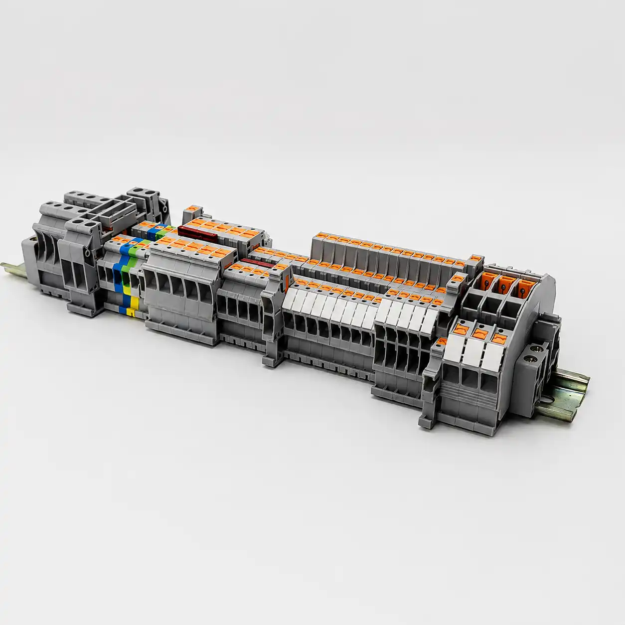
DIN Rail Terminal Blocks
Review the main terminal-block directions for organized field wiring, protective earth, distribution and functional circuit interfaces.
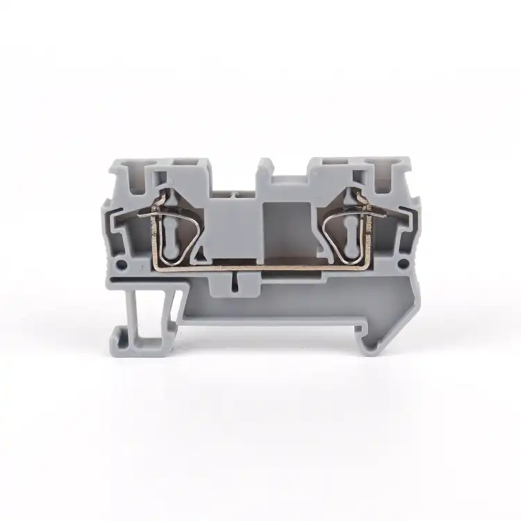
Spring Terminal Blocks
Compare spring-clamp and push-in directions for repeat wiring, compact control panels and applications that benefit from tool-assisted or direct insertion.
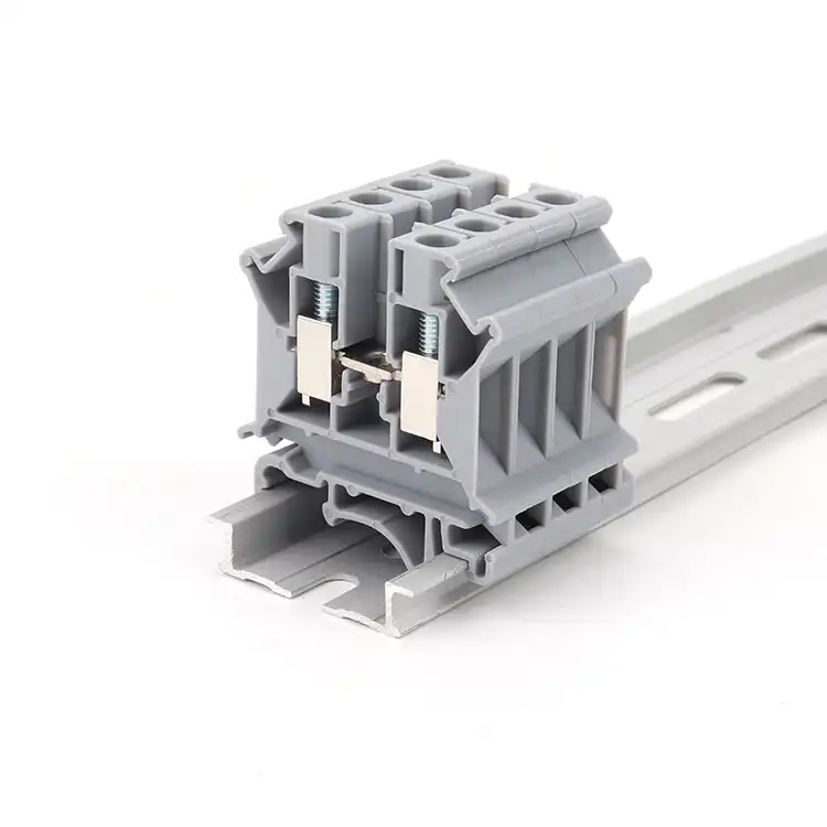
Screw Terminal Blocks
Review screw-clamp terminal families where the selected conductor range, installation practice and maintenance procedure support this connection method.
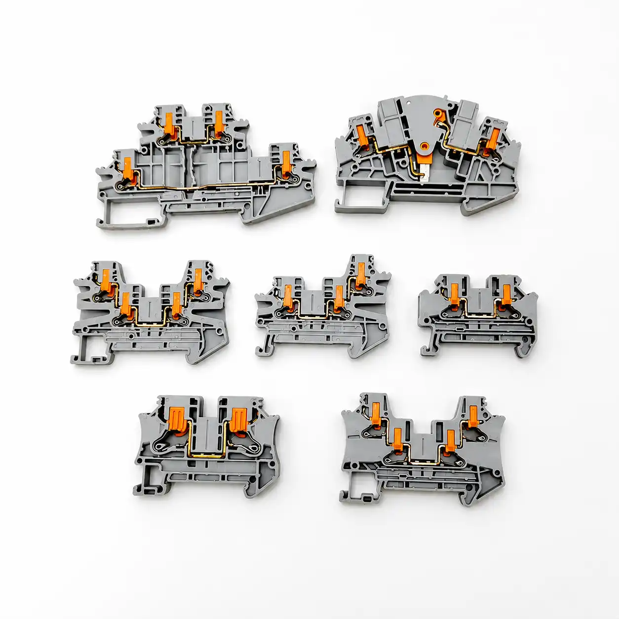
Terminal Block Accessories
Coordinate bridges, markers, end plates, end clamps, DIN rail and wiring duct as part of the finished terminal-strip assembly.
Send enough data to review the whole terminal system
A clear RFQ reduces repeated questions and helps separate fixed requirements from items that still need a recommendation. Photos are useful for replacement work, but drawings and model data remain important.
Standards to review with your panel designer
The applicable standard set depends on the assembly, machine, destination and contract. These references define useful scope for further project review; they are not a substitute for the purchased standards or engineering verification.
Hero photo: Rafael Cosquiere via Pexels.
Questions before component selection
Use these answers to prepare drawings, model data and a more complete RFQ.
What components are needed for control cabinet wiring?
A typical system includes DIN rail, wiring duct, terminal blocks, end clamps, end plates, bridges, markers, PE terminals and wire identification. The complete cabinet may also use protective devices, power supplies, relays, contactors, PLC or I/O modules, interface devices and meters. The exact BOM depends on the schematic, circuit functions and applicable standards.
How should control cabinet components be organized?
Organize components by electrical function and maintenance workflow: incoming power and protection, control power, PLC or interface devices, measurement, field terminals, PE or shield connections and cable entry. The final layout must also account for heat, conductor routing, access, separation, clearances and manufacturer instructions.
Which terminal blocks are commonly used in control panels?
Common directions include feed-through, PE, multi-level, distribution, disconnect, fuse, test and pluggable terminal blocks. Spring, push-in and screw-clamp technologies are available. Selection depends on conductor data, ratings, wiring process, circuit function, rail space, accessories and maintenance needs.
How do I estimate the number of terminal block positions?
Start from the terminal schedule or field I/O list, count ordinary field circuits, PE positions and functional terminals, then add documented spare positions. Review bridge groups, disconnect or test functions, multi-level terminals and distribution blocks separately because they can change both the count and rail length.
What accessories are required for a DIN rail terminal strip?
Depending on the terminal family, a finished strip may require end clamps, end plates, partition plates, fixed or insertion bridges, marker carriers, terminal markers, test accessories and DIN rail. Use accessories approved for the exact terminal series instead of assuming visually similar parts are compatible.
Should power and signal wiring be separated in a cabinet?
The routing and separation plan should be defined from the electrical and EMC requirements of the project, the component instructions and applicable standards. Power, control, communication and measurement circuits may have different routing needs. A qualified designer should document the required arrangement rather than applying one generic distance to every cabinet.
How much spare terminal capacity should a control panel have?
There is no universal percentage for every project. Reserve capacity should reflect expected I/O growth, enclosure space, service strategy, contract requirements and the cost of later modification. Show spare terminal positions and physical rail or duct space explicitly in the drawings and BOM.
Can SENTOP review a terminal strip from a drawing or photo?
Yes. SENTOP can use model numbers, terminal schedules, drawings, photos, dimensions or samples to discuss a replacement or new terminal-strip direction. For accurate selection, also provide conductor data, circuit functions, ratings, quantities, target market and accessory or marking requirements.
What information should be included in a control panel wiring BOM?
List the manufacturer, series, exact model, electrical rating, connection data, quantity, option codes, accessories, marker text or file reference, drawing position and revision. Add packaging, documentation and certification requirements when they are part of the purchase specification.
Can SENTOP supply assembled or marked terminal strips?
Project supply can be discussed for coordinated terminal and accessory sets, marking requirements or representative terminal-strip arrangements. Availability depends on the chosen series, project quantity, approved drawings, label data, testing expectations, packaging and delivery schedule.
Send the schematic, terminal schedule or component list you have now
SENTOP can help you review terminal-block direction, accessory compatibility, marking, bridge groups and supply quantities before the final model list is quoted.
