
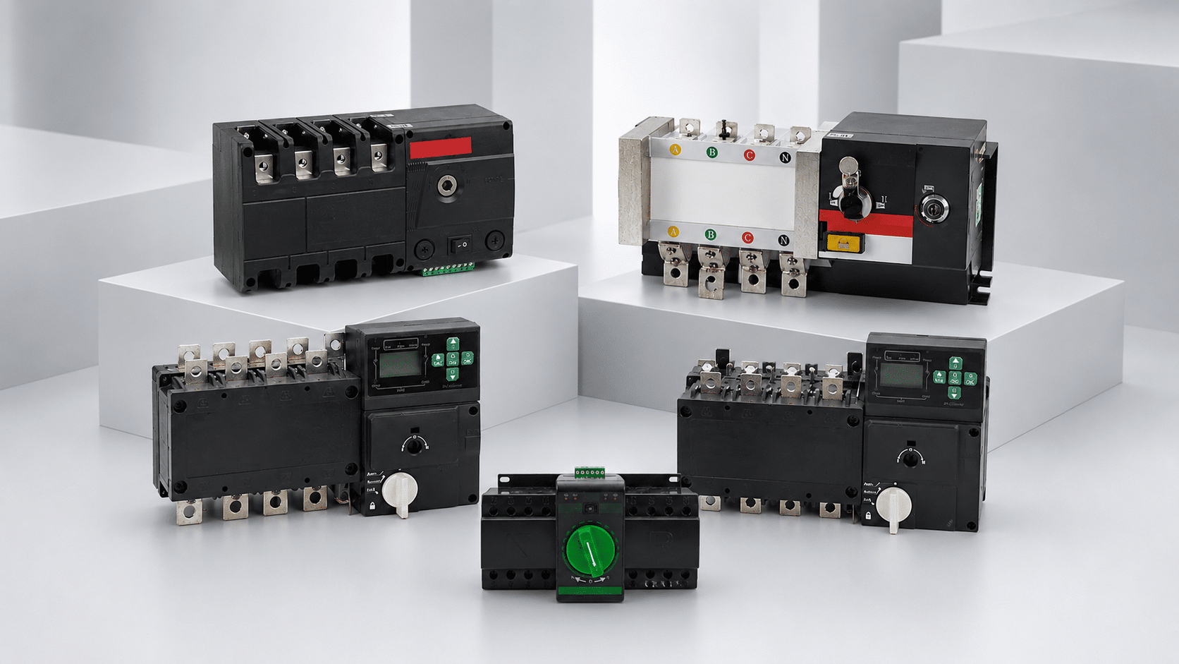
Transfer Switch Wiring Guide for Power, Sensing and Control Circuits
Organize source conductors, load output, voltage sensing, generator start, auxiliary feedback, neutral treatment and protective conductors before panel assembly. The exact terminal numbers and wiring method must always follow the selected transfer switch manual, approved drawings and applicable installation rules.
This guide explains wiring architecture, not a universal terminal diagram
Transfer switches differ in terminal numbering, controller supply, sensing inputs, neutral arrangement, dry-contact ratings and operating sequence. Use the one-line diagram and this guide to prepare a wiring schedule, then complete installation only from the exact product documentation.
Keep power, sensing and control functions clearly identified
A transfer switch panel becomes easier to build and troubleshoot when each conductor is assigned to a defined circuit group before terminal numbers are added.
Normal Source Power
Incoming conductors from the preferred utility or normal source, including the neutral where the system design requires it.
Record: voltage, frequency, phase sequence, poles, upstream device and prospective fault level.Alternate Source Power
Incoming conductors from the generator, second utility or other alternate source, coordinated with its protection and operating limits.
Record: source type, voltage, frequency, neutral arrangement, available current and phase sequence.Load Output
Switched output conductors feeding the downstream panel or defined load group after source transfer.
Record: load current, conductor size, neutral demand, cable route and downstream protection.Sensing, Control & Feedback
Low-energy circuits for source monitoring, generator start, position feedback, alarms, remote commands and communication.
Record: signal type, voltage, dry/wet contact, common reference, shield and external device interface.Separate the power path from the control path
The diagram below is a planning map. It helps identify interfaces and documentation responsibilities without assuming the terminal numbers of a specific ATS or manual changeover switch.

Follow the drawing in five layers
A single-line diagram shows the system architecture, not every control wire. Read it first to establish source ownership, protection and load path; then move to the control schematic and terminal schedule.
The required circuits change with the source arrangement
Select a typical topology to review the interfaces that should appear on the one-line diagram, control schematic and terminal schedule.
Utility-to-generator automatic transfer
The power circuit is only part of the project. Source sensing, controller power, generator start and status feedback must also be matched between the ATS and generator controller.
Dual-utility automatic transfer
Two continuously available utility sources normally require independent source sensing, source priority logic and clear coordination with upstream protective devices.
Manual changeover wiring
A manual transfer switch may remove automatic sensing and generator-start circuits, but power conductor identification, neutral treatment, phase sequence, interlocking and operator indication still require a complete design.
Replacement transfer switch or controller rewire
A similar current rating does not prove wiring compatibility. Existing conductors and I/O must be mapped by function, not transferred terminal-for-terminal by number alone.
Open and closed transition require different system conditions
The contact sequence affects whether both sources are separated during transfer or briefly connected in parallel. It is an equipment and system design decision, not a field wiring shortcut.

Open Transition
The load is disconnected from the first source before it is connected to the second. This prevents intentional source paralleling but creates a defined interruption during transfer.

Closed Transition
The second source is connected before the first source opens, producing a brief parallel condition. This requires equipment specifically designed for closed transition and coordination with both sources.
Do not convert an open-transition system to closed transition through wiring changes. Closed transition must be an engineered, approved capability of the complete transfer equipment and power system.
Do not choose 3-pole or 4-pole wiring by habit
Neutral switching depends on source bonding, earthing arrangement, residual-current protection, generator design and local rules. These conditions must be reviewed as one system.
3-pole transfer arrangement
The phase conductors are transferred while the neutral remains on a continuous common path. This can be appropriate only when the system bonding and protection design supports a common neutral.
4-pole transfer arrangement
The neutral is transferred with the phase conductors. It may be required where the alternate source is treated as a separately derived system or where the approved earthing design requires source neutral separation.
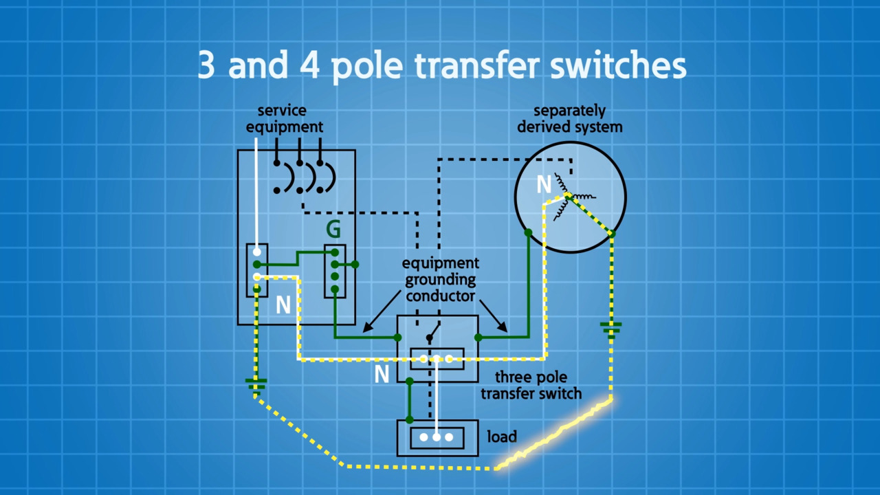
Neutral switching cannot be separated from grounding and bonding
The drawing is useful because it shows the service, generator, neutral and equipment grounding paths together. That complete view is what a simple three-line power diagram often omits.
Label every signal by function and electrical type
A terminal name such as START, AUX or ALARM is not enough. Record whether the circuit is a dry contact, powered input, relay output, analogue input or communication connection.
Source Voltage Sensing
Allows the controller to evaluate normal and alternate source availability, phase condition and frequency.
Confirm sensing voltage, phase references, protective device, terminal common and controller limits.Generator Remote Start
Commands the generator controller when the normal source is unavailable and releases it after retransfer and cool-down.
Confirm dry/wet contact, maintained/pulse logic, contact rating and generator controller input.Switch Position Contacts
Reports normal, alternate, OFF or mechanism position to lamps, a PLC, BMS or remote annunciator.
Confirm contact state with the switch in each position and never assume NO/NC from the label alone.Inhibit, Test or Manual Command
Provides approved remote functions such as transfer inhibit, test sequence or manual source command.
Confirm input priority, fail-safe state, authorization, external voltage and interaction with local controls.Common Alarm & Source Status
Communicates source failure, transfer failure, switch position or controller alarm to another system.
Confirm relay rating, normal state, alarm reset behavior and whether multiple alarms share a common.Communication Interface
Connects the transfer controller to monitoring systems using a model-supported protocol.
Confirm protocol, baud rate, address, register map, shield termination, isolation and network topology.Prepare the conductor schedule before cutting cable
The schedule should connect the one-line diagram to the physical panel: conductor identity, terminal destination, cable data, tightening requirement and inspection record.
| Check item | What to document | Why it matters |
|---|---|---|
| Source and load identity | Normal source, alternate source and load tags repeated at the switch and both cable ends. | Prevents source/load reversal and makes isolation and maintenance clearer. |
| Phase sequence | Phase designation and verified sequence for both sources before connection to sensitive loads. | Prevents rotation reversal and failed synchronization or transfer checks. |
| Conductor range | Material, cross-section, insulation rating, flexible/solid form and number of conductors per terminal. | Must remain within the exact terminal and lug capability stated by the manufacturer. |
| Lug and preparation | Approved lug type, strip length, ferrule where applicable and crimp tooling. | Reduces loose joints, damaged strands and unsuitable contact surfaces. |
| Tightening data | Model-specific torque or tightening method plus inspection responsibility and record. | Under-tightening and over-tightening can both damage the connection. |
| Clearance and routing | Bend radius, cable support, heat sources, barriers and segregation between power and control wiring. | Protects insulation and reduces mechanical stress and interference. |
| Terminal references | Terminal number, wire ID, origin, destination, function and drawing cross-reference. | Creates a serviceable link between the schematic and the installed panel. |
Important: The permissible conductor type, quantity per terminal, accessory lug and tightening value are product-specific. Obtain them from the exact model documentation rather than applying a value from a similar switch.
Prevent faults that are difficult to find after energization
Most wiring problems begin with an incorrect assumption about terminal function, source arrangement or controller interface.
Source and load terminals reversed
Physical position is not a reliable guide. Identify terminals from the model diagram and verify every conductor against the schedule.
Phase sequence differs between sources
Both sources may have correct voltage but a different phase sequence, causing load rotation or transfer problems.
Neutral and bonding assumed
Selecting three or four poles without reviewing the full earthing arrangement can create parallel paths or protection issues.
Generator start logic misunderstood
A dry-contact output, powered signal, pulse command and maintained command are not interchangeable.
Controller supply confused with sensing
Some controllers use separate power and source-sensing terminals. Combining them without confirmation can cause incorrect operation.
Auxiliary common reference missed
Position and alarm contacts may have different commons or ratings. Map each contact in every switch state before integration.
Use the symptom to choose the next document and check
Troubleshooting should be performed by qualified personnel under an approved safe method. The list below organizes likely interfaces to review; it does not instruct work on energized equipment.
Review ATS source-failure detection, start delay, generator-start relay state, contact rating, cable continuity and the generator controller remote-start input.
Check alternate-source sensing, voltage/frequency acceptance limits, phase condition, transfer inhibit, controller mode, time delays and mechanism status.
Compare phase sequence between the normal and alternate sources and review the complete downstream motor application before further operation.
Review normal-source sensing, source-stability and retransfer delays, preferred-source settings, inhibit inputs, manual mode and active alarms.
Map the auxiliary contact common, NO/NC state, external control voltage and PLC/BMS input logic for every mechanical switch position.
Compare the old and new controller by function: sensing references, normal contact state, supply voltage, input polarity, communication and alarm reset behavior.
Transfer equipment works with organized wiring and monitoring
SENTOP can review the transfer switch together with terminal blocks, identification accessories and panel meters when these products belong to the same control cabinet or purchasing requirement.
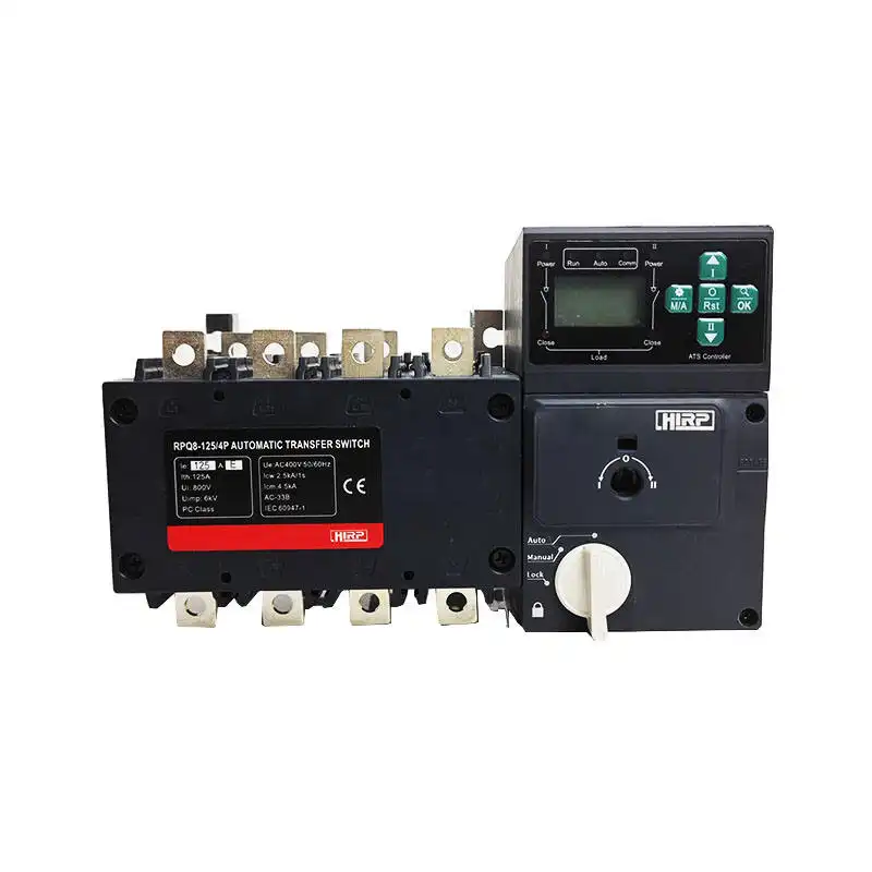
Automatic Transfer Switch
For utility-generator and dual-source systems that require automatic source monitoring, transfer logic, generator start and status feedback.

Terminal Blocks & Accessories
Organize field wiring, control circuits, source status and serviceable panel connections.
Explore terminal systems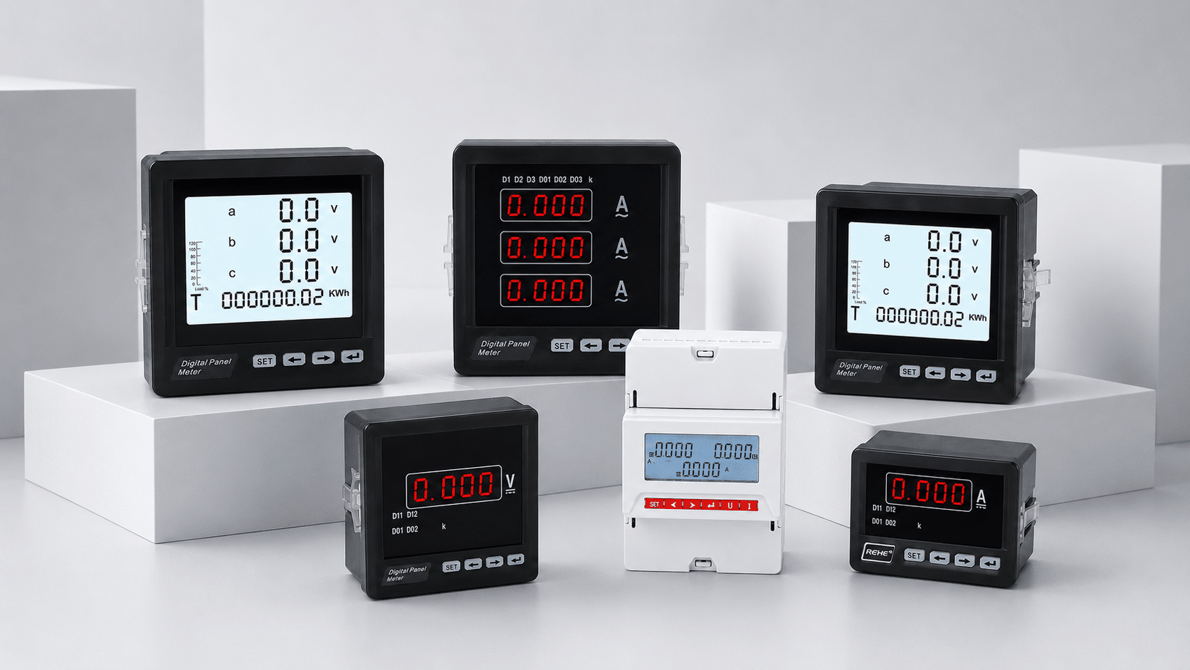
Digital Panel Meters
Display source or load values and support defined communication requirements.
Explore panel metersTest the complete transfer sequence, not only continuity
Commissioning should be planned by qualified personnel under an approved method. The final record should prove the power path, controller logic, source acceptance and every required remote signal.
Review approved drawings
Confirm the one-line, control schematic, terminal schedule, settings, equipment manuals and protection data are the current revision.
Inspect and verify terminations
Check identification, conductor preparation, routing, clearances, tightening records, neutral and protective bonding.
Verify both source conditions
Confirm voltage, frequency, phase sequence and source-specific acceptance limits using an approved test procedure.
Prove inputs and outputs
Test sensing, generator start, position contacts, alarms, remote commands and communication against the I/O list.
Run the approved sequence
Verify start delay, source acceptance, break-before-make operation, transfer time and load behavior.
Check retransfer and cool-down
Confirm normal-source stability delay, retransfer, generator cool-down and final source position.
Verify permitted failure responses
Test approved alarm, inhibit and unsuccessful-transfer conditions without creating unsafe operating states.
Record settings and results
Issue final drawings, terminal schedule, settings, test results, operating procedure and maintenance information.
Send the system data that controls the wiring
A model number alone may not show the complete interface. Include the available one-line diagram, source data and required control functions so SENTOP can review the appropriate product direction and documentation.
Source and load data
Normal and alternate voltage, frequency, phases, current, fault level, poles, neutral and earthing arrangement.
Required I/O
Generator start, source sensing, switch position, alarms, remote commands and communication requirements.
Application and supply
Equipment type, installation environment, target market, quantity, enclosure, delivery and document requirements.
Use the guide with the applicable design rules
Standards define equipment or installation scope, but the approved project design and exact manufacturer instructions determine the final terminals, settings and wiring method.
IEC 60947-6-1:2026
Covers low-voltage transfer switching equipment, including manually operated, remotely operated and automatic transfer switching equipment within its stated scope.
View official IEC scopeIEC 60364-5-53
Addresses selection and erection requirements for devices used for protection, isolation, switching, control and monitoring in low-voltage installations.
View official IEC scopeISO 8528-4:2025
Specifies criteria for controlgear and switchgear associated with reciprocating-engine-driven AC generating sets within its defined applications.
View official ISO scopeQuestions before panel wiring
Use these answers to prepare drawings and questions for the switch manufacturer, panel builder or responsible electrical designer.
Is there one universal transfer switch wiring diagram?
How can I identify source and load terminals?
How is generator start connected to an ATS?
Should a transfer switch use three poles or four poles?
Is the protective earth conductor switched?
Are source sensing wires the same as controller power wires?
Can auxiliary contacts be connected directly to a PLC or BMS?
What should be checked before energizing a transfer switch panel?
Have a transfer switch model, one-line diagram or terminal question?
Send the source data, load current, pole arrangement, generator controller information and required feedback signals. SENTOP will help organize the product and documentation review before ordering.
