
Transfer Switch Selection Guide for Manual and Automatic Changeover
This transfer switch selection guide helps you choose from the source arrangement, operating method, electrical ratings, load type, poles, neutral and grounding design, switching class, protection strategy, control logic and installation conditions. Use it to define a valid selection direction before requesting an exact SENTOP model.
What should you choose first?
A practical transfer switch selection guide starts by deciding how the load must move between two sources. Choose manual operation when a qualified operator is available and a planned interruption is acceptable. Choose automatic operation when the system must monitor source conditions and transfer without waiting for an operator. Then define both sources, the load, poles and neutral, protection, control functions and installation.
This guide addresses electromechanical transfer switching equipment. Static transfer switches, UPS systems, source paralleling and multi-source control require a different design review.
Define continuity and operation
Manual, remotely initiated or automatic transfer starts from the operating requirement.
Describe both power sources
State utility, generator or second utility data and identify the preferred source.
Describe the connected load
Confirm current, utilization duty, inrush, allowable interruption and restart behavior.
Choose poles, class and protection
Coordinate neutral and grounding, switching path and available fault current.
Confirm control and installation
Review sensing, delays, I/O, mounting, enclosure, documents and testing.
Find the right transfer-switch starting point
Answer three project questions to identify a practical product-page direction. This planning tool does not select a final model or replace the electrical system review.
Choose manual or automatic transfer from the continuity requirement
The operating method is a system decision, not a price tier. Define who detects a source problem, who starts the alternate source, how transfer is authorized and what interruption the connected load can accept.
Manual Transfer Switch
A manual transfer switch remains on one source until a qualified operator changes the switch position. It suits systems where attended operation and a planned interruption are acceptable.
Automatic Transfer Switch
An automatic transfer switch monitors source conditions and operates according to controller logic. In generator systems it may also issue a generator start signal and manage retransfer.
IEC 60947-6-1:2026 addresses manually operated, remotely operated and automatic transfer switching equipment, together with other defined TSE forms. Always verify the exact edition required by the destination project and the model-specific compliance evidence.
Define what the switch is transferring between
The second source changes the controller sequence, available-power logic and project interfaces. Identify both sources and the preferred source before evaluating a product family.
| Source arrangement | Typical transfer objective | Key questions | Useful next page |
|---|---|---|---|
| Utility to generator | Move selected loads to standby generation after a qualifying normal-source failure. | How is the generator started? When is it acceptable? What are warm-up, retransfer and cool-down requirements? | Generator Transfer Switch Solution |
| Utility to utility | Move the load between two available or independently monitored utility sources. | Which source is preferred? Are both sources normally energized? What return, inhibit and transition logic is required? | Automatic Transfer Switches |
| Generator to generator | Coordinate two generator sources in a project-specific standby or prime-power arrangement. | How are starts, source priority, load capacity, failures, maintenance and fuel constraints managed? | |
| Replacement of an existing switch | Restore the intended source-changeover function without creating mechanical or electrical incompatibility. | Does the replacement match terminals, dimensions, ratings, poles, neutral, protection, controller I/O and sequence? |
A transfer switch connects a load to one of two power sources. It is not a source-paralleling system, UPS or substitute for the upstream and downstream protection design.
Build the specification from nine electrical decisions
These items determine whether two switches with a similar current label are actually suitable for the same installation.
Voltage and frequency
State each source's nominal voltage, phase system and frequency. Identify differences between normal and alternate sources.
Check both sources separatelyRated current and load
Use calculated continuous current and load behavior, including motors, transformers, UPS, drives, lighting and mixed circuits.
Do not copy the panel main rating blindlyPoles and neutral
Define 2P, 3P or 4P from phase conductors, neutral switching, generator bonding and the grounding design.
Neutral design comes before pole countSwitching class
Choose the PC or CB direction from the switching and overcurrent-protection architecture, not from the product appearance.
Verify exact class and constructionShort-circuit coordination
Provide available fault-current information and the upstream protective devices on both source paths.
Check model-specific withstand dataTransition method
Define open, delayed or another project-required transition from the load behavior and complete source relationship.
Confirm the mechanism supports itSensing and delays
Specify source acceptance, failure confirmation, transfer, retransfer and generator-related timing only where required.
Use a written sequence of operationControl and communication
List auto/manual modes, test, inhibit, generator start, alarms, position outputs, remote commands and communication.
Provide the BMS or I/O listMounting and enclosure
State open-device or enclosed supply, panel space, mounting, cable entry, terminals, ambient conditions and enclosure rating.
Send the layout drawingChoose PC or CB from the protection strategy
The class affects how the transfer equipment is coordinated with overcurrent protection. Always use the marking and technical data for the exact complete TSE model.
PC Class Transfer Switch
A PC direction is selected when the transfer switching path and separately coordinated protective devices form the required system architecture.
CB Class Transfer Switch
A CB direction is evaluated where circuit-breaker overcurrent release functions are part of the complete transfer equipment and protection design.
Obtain system data
Determine the available fault current at the transfer-switch location for each source path.
Identify protective devices
Record the utility-side device, generator breaker and required tripping relationship.
Verify exact ratings
Compare the complete model's withstand, making, interruption and conditional data as applicable.
Release the coordinated system
Keep the accepted model, protection assumptions and technical evidence tied to the project record.
Do not choose pole count or transition in isolation
Pole configuration comes from the phase and neutral scheme. Transition comes from source relationship, load behavior and the approved operating sequence.
| Decision | Common direction | Questions to answer | Release check |
|---|---|---|---|
| 2-pole | Single-phase systems where two conductors are switched. | Which conductors are live? Is the neutral included? What is the grounding arrangement? | Single-line diagram, voltage, neutral and terminal identification. |
| 3-pole | Three-phase systems with a solid neutral, or a project-specific single-phase switched-neutral arrangement. | Does the neutral remain connected? Are the two sources separately derived? | Grounding study and exact product pole definition. |
| 4-pole | Three-phase systems where the neutral must be switched. | How is each source neutral bonded and grounded? Is a fully rated neutral pole required? | Approved neutral/grounding diagram and model data. |
| Open transition | Disconnect one source before connecting the other. | Can the load tolerate the interruption? How do motors, transformers, UPS or controls respond? | Mechanism sequence, operating time and load review. |
| Delayed transition | Hold the load disconnected for a defined interval or condition before connecting the alternate source. | Is a center-off position required for residual voltage or load behavior? | Exact mechanism capability and controller timing. |
| Other transition requirements | Project-specific schemes requiring additional synchronization, interconnection or approval. | Are the sources ever paralleled? Which utility and code approvals apply? | Dedicated engineering review; do not infer suitability from a standard ATS description. |
Neutral switching and transition selection affect grounding, fault paths and load behavior. These decisions should be released by the responsible system designer, not guessed from the number of visible terminals.
Move from application to model through controlled decisions
A repeatable sequence prevents missing parameters and makes supplier quotations comparable. Keep each accepted decision with the final item code and drawing revision.
Continue from the guide to an exact product review
The following families are starting points. Confirm the complete model, ratings, controller, poles, class, dimensions and documents before placing an order.
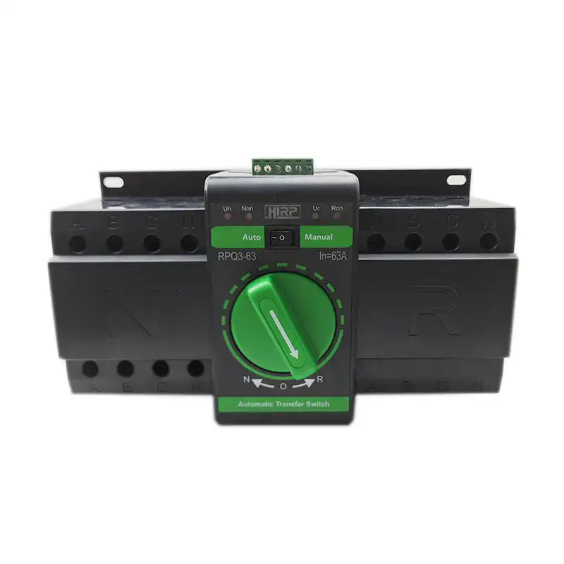
Compact Automatic Transfer Switch
A compact direction for smaller distribution boards and equipment panels where space, terminal capacity, load type and basic automatic transfer functions must be coordinated.
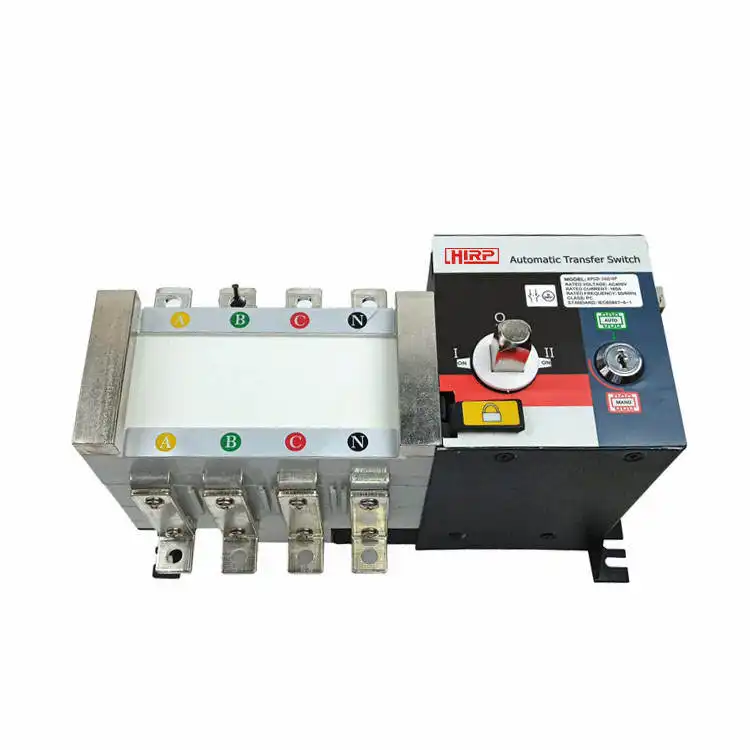
Generator Automatic Transfer Switch
A generator-oriented direction for normal-source monitoring, generator start, alternate-source acceptance, load transfer, retransfer and cool-down control.
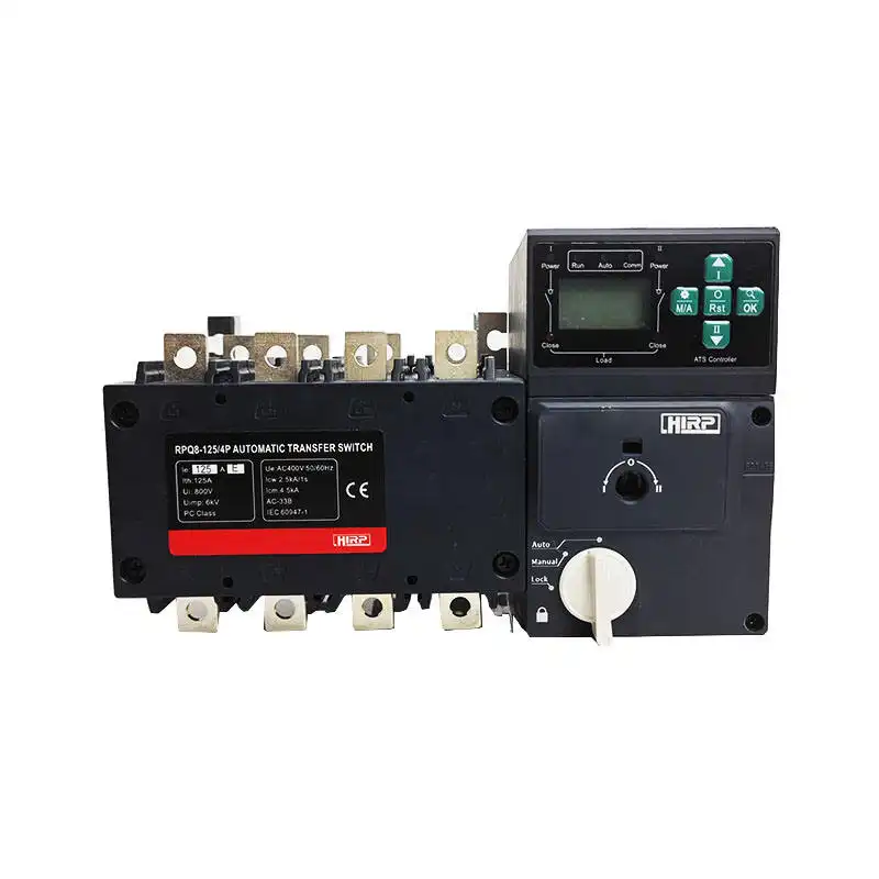
RPQ8 Automatic Transfer Switch
An industrial ATS direction for projects requiring configurable sensing, timing, modes, status indication and coordinated remote interfaces.
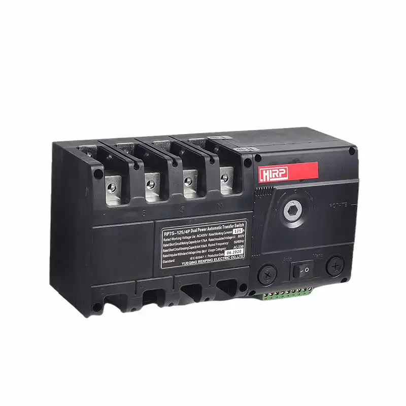
RP7S Automatic Transfer Switch
A molded-case direction for industrial and commercial distribution where frame, current, poles, class, protection data and controller functions require detailed review.
Let the load and operating procedure drive the choice
Industry labels alone do not select a transfer switch. Use each application to identify the deciding technical questions.
Commercial distribution
Selected lighting, pumps, communication, access and building-service loads may require coordinated automatic backup power.
Review load priority, fire interface and BMS pointsIndustrial machinery
Motors, drives, transformers and controls can change current, utilization duty, transfer behavior and restart requirements.
Review inrush, process state and restart sequenceGenerator packages
Utility-to-generator systems need a defined start interface, source acceptance, transfer, retransfer and cool-down sequence.
Review genset controller, neutral and load capacityTelecom and remote sites
Unattended sites often depend on alarms, remote status, communications, environmental protection and service access.
Review monitoring, enclosure and maintenance methodOEM electrical equipment
A confirmed transfer-switch configuration can be integrated into repeatable equipment with controlled drawings and labels.
Review approved BOM, interfaces and change controlExisting-equipment replacement
A replacement must preserve the intended electrical and mechanical interfaces, not merely match current and pole count.
Review photos, dimensions, terminals and sequenceSend a complete transfer-switch requirement
A useful quotation identifies the source system, load, transfer method, protection and supply scope. More complete input produces a more comparable technical and commercial response.
Describe the electrical system
Both sources, voltage, frequency, phase, current, load type, available fault current, protective devices, poles, neutral and grounding.
Describe the operation
Manual or automatic, preferred source, transition, sensing, delays, generator start, alarms, test, remote I/O and communication.
Describe the supply
Open or enclosed form, dimensions, quantity, destination, standards, certificates, drawings, labels, packaging and schedule.
Verify more than the nameplate current
For a replacement or repeat project, keep the approved electrical function and physical interfaces visible through selection, sample review and ordering.
Continue to the right selection path
Questions to answer before selecting a transfer switch
These answers establish the selection direction. The exact product must still be confirmed against model-specific technical data and project requirements.
How do I choose a transfer switch?
Start with manual or automatic operation and the two-source arrangement. Then confirm voltage, frequency, current, load type, poles, neutral and grounding, switching class, protection, transition, controller functions, installation and required documents.
What is the difference between a manual and automatic transfer switch?
A manual transfer switch requires a qualified operator to initiate the changeover. An automatic transfer switch monitors source conditions and operates according to controller logic without waiting for an operator. Choose from the continuity requirement and operating procedure.
How do I size the current rating of a transfer switch?
Use the calculated load current and applicable design requirements, then consider load type, utilization duty, inrush, continuous operation, terminals, ambient conditions and the exact product ratings. Do not select only from generator capacity or panel main rating.
Should I choose a 3-pole or 4-pole transfer switch?
The choice depends on whether the neutral remains solidly connected or must be switched. Generator neutral bonding, system grounding and applicable project rules should determine the pole arrangement.
What is the difference between PC and CB class?
PC and CB are different transfer-switching equipment directions within the protection architecture. PC selection normally requires coordinated external protective devices, while CB selection incorporates breaker-based overcurrent release functions. Verify the exact complete TSE construction and model data.
Does a transfer switch provide overload and short-circuit protection?
It depends on the class and exact construction. Some transfer equipment relies on coordinated upstream protection, while breaker-based equipment may include overcurrent releases. The available fault current and all protective devices must be reviewed together.
Can I use the same transfer switch for utility-to-utility and utility-to-generator systems?
Some product platforms may support different source arrangements, but the controller logic and interfaces differ. Generator systems require start and cool-down coordination, while utility-to-utility systems need their own source priority and return logic. Confirm the exact model and settings.
What transition type should I choose?
Choose the transition method from the source relationship, allowable interruption and load behavior. Motors, transformers, UPS systems and sensitive controls may require additional review. Confirm that the exact switching mechanism supports the required sequence.
Can a transfer switch replace a circuit breaker?
Not automatically. A transfer switch connects a load between sources, while a circuit breaker performs defined protection and interruption functions. The TSE class and complete protection design determine which protective devices are required.
What controller functions should I specify for an ATS?
Specify source sensing, acceptance limits, delays, preferred source, auto and manual modes, generator start, test, alarms, position outputs, inhibit or fire inputs, remote commands and communication required by the project.
What should I send for a replacement transfer switch?
Send the complete model and nameplate, photos, single-line and wiring diagrams, dimensions, terminals, sources, voltage, frequency, current, poles, neutral, class, protection, controller functions and required documents.
What information should be included in a transfer switch RFQ?
Include both power sources, electrical ratings, load information, available fault current, protective devices, operating method, poles, neutral, transition, control sequence, I/O, communication, mounting, enclosure, quantity, destination, standards and documents.
Send your source, load and transfer requirements
SENTOP can review the selection direction from your single-line diagram, existing model, photos or project specification before confirming a quotation.
