
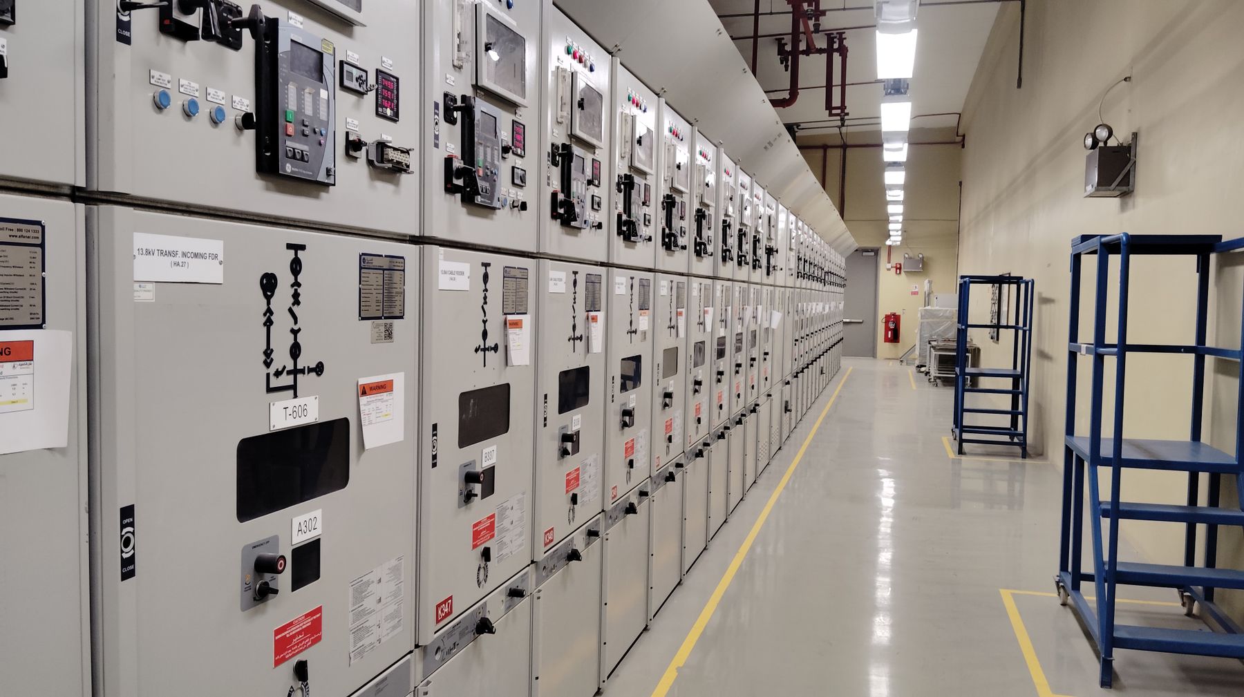
Panel Meter Selection Guide: Choose in 7 Steps
This panel meter selection guide starts with the electrical signal, not the display. Define what must be measured, AC or DC, the phase and wiring system, direct or transformer input, panel cutout, required accuracy, communication and outputs. Only then compare a dedicated voltmeter, ammeter, multifunction meter or connected RS485 model.
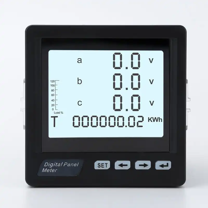
Confirm the exact datasheet, terminal diagram and option code before ordering.
What must the operator know or do?
A clear use case shortens the specification. A local readout, a three-phase power monitor and a meter that sends data to a PLC may share a similar front size, but their input circuits, wiring and commissioning requirements are different.
Show one electrical value
Choose a dedicated voltmeter or ammeter when the operator needs a simple, permanent local indication and the measured range is already known.
Best starting point: dedicated meterMonitor a three-phase feeder
Use a multifunction direction when voltage, current, frequency, power or energy must be viewed from one panel position. Confirm the exact supported quantities.
Best starting point: multifunction meterSend readings to a controller
A communication port is only the physical path. The protocol, baud rate, address settings and register map must also match the PLC, gateway or SCADA system.
Best starting point: connected meterTrigger an alarm or output
Confirm whether the project needs relay setpoints, pulse output, analog retransmission or a communication message. Do not assume every model includes every option.
Best starting point: output-capable modelPanel meter selection in seven decisions
Use these steps in order. Each answer removes incompatible products before price, appearance or delivery is compared.
Define the quantity and operating range
State the actual variable: AC voltage, DC current, frequency, single-phase power, three-phase power or energy. Include normal and maximum values, not only a broad category such as "electrical meter."
A voltmeter or ammeter is efficient when one value must remain visible and no calculation between several channels is needed.
"Current meter" is incomplete. A useful request states AC or DC, expected current, overload conditions and whether a CT or shunt is already selected.
Confirm AC or DC and the wiring arrangement
For AC systems, identify single phase, three-phase three-wire or three-phase four-wire. For DC systems, define polarity, direct voltage input and any external current shunt.
Provide nominal line voltage, frequency, phase arrangement and whether neutral is available. The meter's voltage terminals and calculation method must suit the system.
Provide nominal and maximum voltage or current, polarity behavior, shunt output if used, and whether the display needs bidirectional measurement.
Match direct input, CT, VT or shunt
The meter rarely sees the same electrical quantity in the same way at every installation. High current may be transformed by a CT; DC current may be converted through a shunt; higher voltage may require a VT or transducer.
State the CT primary and secondary values, VT ratio or shunt rating. The meter must accept the sensor output and be configured to display the primary value.
Selection and installation must follow the meter and CT documentation. Confirm terminal assignment, polarity and safe commissioning procedures before energizing.
Measure the panel before choosing the face
Face dimensions alone do not confirm fit. Record the existing cutout, available depth, panel thickness, mounting method, rear clearance and terminal access.
Choose the viewing size and layout first, then reserve cutout, wiring bend radius and service access in the cabinet drawing.
Send a front photo, rear photo, label, cutout measurement and depth. A close face size does not guarantee a drop-in replacement.
Choose accuracy for the real purpose
Separate display resolution from measurement accuracy. Specify the tolerated error, reference conditions, update behavior and whether the reading is for operational monitoring, control, testing or commercial energy settlement.
For cabinet status and maintenance, readability, stable indication, repeatability and correct range matching may matter more than extra display digits.
Do not use a general monitoring meter for revenue or regulated settlement unless the exact model, accuracy class and approvals are documented for that duty.
Define what happens after the value is measured
Decide whether the result stays on the display or must trigger a relay, produce a pulse, retransmit an analog signal or travel over a serial network.
Confirm protocol, baud rate, parity, address range, data format and register map. RS485 describes an electrical interface, not the complete application protocol.
State relay quantity, contact duty, high/low logic, hysteresis, delay and fail-state expectations. Verify whether the output is standard or optional.
Review documents and test a sample
Before a project or repeat order, compare the exact model code against the datasheet, terminal diagram, communication document, dimensions, markings and required compliance evidence.
Check power-up, scaling, CT or shunt ratio, display direction, communication, outputs and behavior near expected operating limits.
Freeze the approved model code, option code, firmware or register-map reference, label language, packaging and accepted sample evidence.
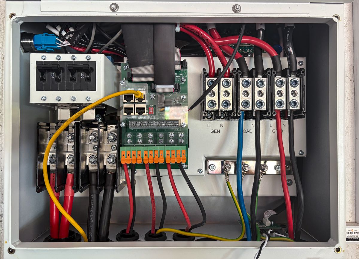
Select the meter and its measurement chain together
A correct front-panel meter can still produce a wrong reading when the transformer ratio, wiring mode, polarity or configuration is wrong. Use the one-line diagram and sensor data as selection inputs.
State line voltage, frequency, direct or CT current input and whether the meter needs only V/A or also power and energy.
Confirm the meter supports the intended three-wire measurement method and the corresponding voltage/current terminal arrangement.
Confirm neutral availability, line-to-line and line-to-neutral values, CT quantity and the displayed or transmitted parameters.
Match the meter input to the shunt output, define the primary current and preserve polarity. Do not substitute a shunt ratio without checking the meter input specification.
Choose the simplest meter that covers the complete duty
More functions are useful only when the project will configure, document and use them. This table is a selection direction, not a substitute for an exact model datasheet.
| Meter direction | Best used when | Input questions | Integration questions | Typical risk |
|---|---|---|---|---|
| Digital voltmeterOne local voltage value | Operators need a clear AC or DC voltage indication without extra parameters. | AC/DC, direct range, line relationship, frequency and supply. | Usually display only; verify any alarm or communication option separately. | Assuming the indicated voltage range equals the safe direct input range. |
| Digital ammeterOne local current value | A feeder, load or DC circuit needs a permanent current indication. | Direct, CT or shunt input; ratio; overload; polarity for DC. | Display, alarm, analog or serial output as required. | Ordering by primary current without defining the CT secondary or shunt signal. |
| Three-phase ammeterPhase current comparison | Three phase currents must be reviewed without installing three separate displays. | System wiring, CT quantity and ratio, current range and display sequence. | Check whether phase values can also be transmitted and how they are mapped. | Using a meter intended for another wiring configuration. |
| Multifunction meterFeeder power monitoring | Voltage, current, frequency, power factor, power or energy must share one panel position. | 3P3W/3P4W, voltage input, CT/VT ratios and supported calculations. | Protocol, registers, outputs, event or energy data requirements. | Assuming every multifunction model calculates every requested quantity. |
| RS485 panel meterConnected monitoring | Values must be collected by a PLC, gateway, BMS or SCADA system. | All electrical input questions still apply before communication is considered. | RS485 wiring plus protocol, baud, parity, address and register map. | Treating "RS485" and "Modbus RTU" as complete, interchangeable specifications. |
For regulated power metering and transformer-operated active-energy metering, review the applicable project standard and the exact device documentation. General panel monitoring and commercial settlement are not automatically the same duty.
Build your meter direction
Answer five questions to create a practical starting point. The result identifies a product direction and the missing data that SENTOP should review before an exact model is quoted.
- No model is selected from appearance alone.
- Input method can override the basic meter type.
- Communication never replaces electrical compatibility.
Translate the requirement into a product direction
The examples below organize an inquiry. The exact model must be confirmed against the current product document and the customer's electrical system.
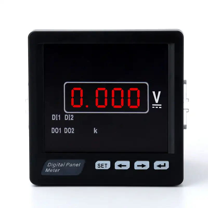
RM-DV31 intelligent digital panel meter
A starting direction for projects that need a clear panel-mounted electrical indication. Confirm AC or DC signal, direct input or transformer method, measuring range, cutout, auxiliary supply and exact options.
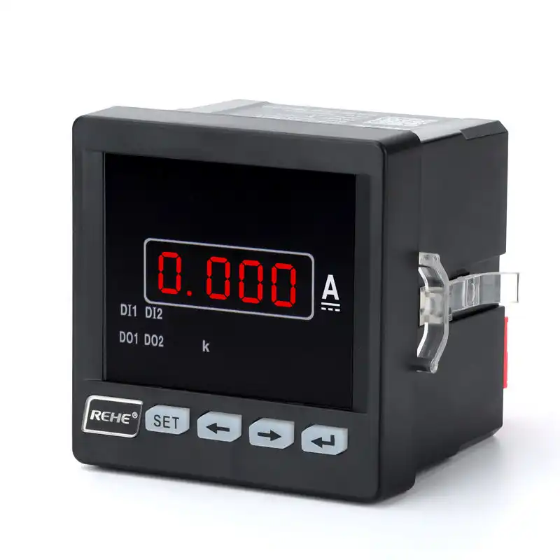
RN-DA31 LED DC ammeter
A direction for DC current indication in equipment, battery-related panels and control systems. Confirm whether the measured current is direct or uses an external shunt, then match shunt signal, ratio and polarity.
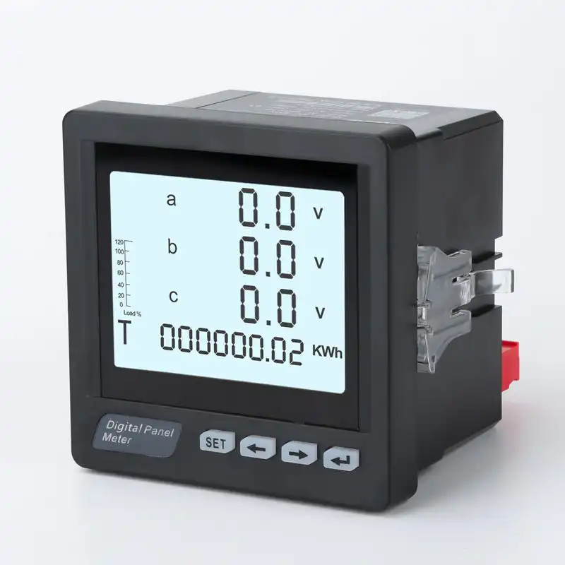
RM-3AA3Y three-phase digital ammeter
A direction for viewing three-phase current from one panel position. Confirm the system wiring, CT quantity, primary/secondary ratio, current range, 96 x 96 mm format requirements and any output needs.
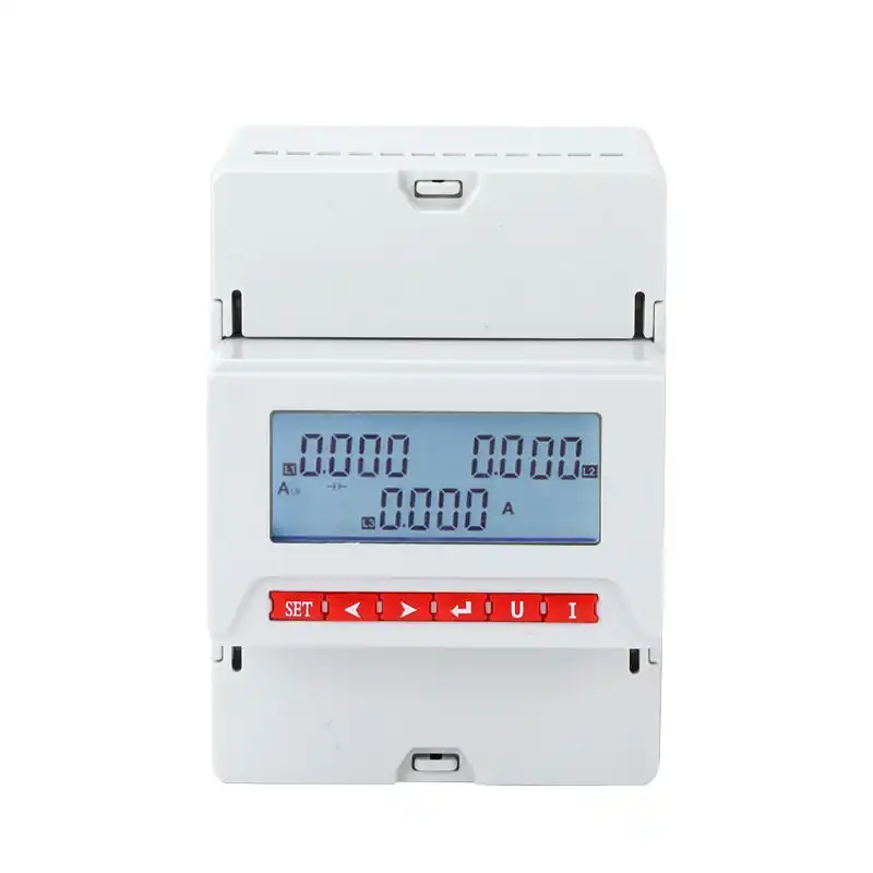
RS485 LCD digital panel meter
A direction for projects that need local display plus networked readings. Electrical measurement compatibility remains the first requirement; then verify Modbus support, serial settings, register map and system integration.
Six common panel meter selection mistakes
Most of these problems are prevented before quotation by sending one-line diagrams, sensor ratios and mechanical dimensions together.
Choosing by face size
The same front dimensions can hide different cutouts, depths, terminal layouts, supply ranges and input circuits. Verify every mechanical and electrical interface.
Confusing direct range with displayed range
A meter may display the primary current after scaling while its input receives a CT secondary or shunt signal. State both sides of the measurement chain.
Ignoring the phase/wire system
A three-phase label does not prove compatibility with every 3P3W or 3P4W installation. Confirm the exact wiring diagram and supported calculations.
Specifying RS485 only
Integration also requires the protocol, serial settings and register definitions. Obtain the current communication document before PLC or SCADA programming.
Comparing display digits instead of accuracy
Resolution, range and accuracy are different specifications. Review the error statement and reference conditions for the application's real purpose.
Skipping the approved sample record
Without a frozen model code, option set, label and test evidence, repeat orders can become ambiguous even when the product family name is unchanged.
Send a specification that can be matched without guessing
Check each item you already have. The progress bar shows whether the inquiry contains the core information needed for an efficient model review.

Use standards and protocol documents for the final decision
These sources define important contexts for power monitoring, transformer-operated energy metering and Modbus integration. The applicable requirement depends on the project and market.
Covers performance measuring and monitoring devices used in electrical distribution systems. Use it to frame documented performance requirements where applicable.
View IEC publicationAddresses particular requirements for specified transformer-operated static active-energy meters. It is relevant when the duty extends beyond general panel indication.
View IEC publicationThe application protocol and serial-line guidance are separate documents. Confirm both the physical network and the device's implementation details.
View Modbus specificationsAutomationDirect's guide organizes measurement type, signal compatibility, display, environment, outputs, supply, calibration and installation considerations.
Open the official guideQuestions to settle before ordering
Use these answers to prepare the inquiry, then validate the exact product documentation for the selected model.
How do I choose the right digital panel meter?
Should I choose a dedicated meter or a multifunction panel meter?
What information is needed to select a digital ammeter?
What is the difference between direct input, CT input and shunt input?
Can the same panel meter work with 3P3W and 3P4W systems?
Does RS485 mean the meter uses Modbus RTU?
How do I select the correct panel meter cutout?
Are more display digits the same as higher accuracy?
Can a panel meter replace an HMI?
Can a monitoring meter be used for billing?
What should I test on a sample meter?
What should I send SENTOP for panel meter model matching?
Turn your panel data into a clear meter specification
Send the one-line diagram, expected range, CT/VT/shunt data, panel dimensions and communication needs. SENTOP can review the requirement and organize a model direction for sample or project quotation.
