
Automatic Transfer Switches for Reliable Dual-Source Power Control
Select an ATS for utility-to-utility or utility-to-generator systems from the actual voltage, frequency, load current, poles, neutral arrangement, short-circuit coordination, controller logic and communication requirements. SENTOP supports model matching, drawings, samples and OEM bulk supply.
What does an automatic transfer switch do?
An automatic transfer switch monitors two power sources and transfers the connected load when the preferred source is unavailable or outside the configured limits. In a generator system, the controller may also issue a remote start signal, wait for the alternate source to stabilize and return the load after normal power is restored.
An ATS does not replace a complete power-system design. Source protection, grounding, neutral treatment, conductor sizing, fault-current coordination, generator controls and local electrical rules must be reviewed together with the exact switch model.
Monitor the preferred source
Check voltage, frequency, phase condition and controller-defined acceptance limits.
Confirm a persistent source problem
Use the configured delay to avoid an unnecessary transfer for a brief disturbance.
Prepare the alternate source
Verify the second utility source or start and stabilize the standby generator.
Transfer and later retransfer the load
Operate the switching mechanism in the approved sequence, then return after normal power is stable.
Choose PC or CB class from the short-circuit strategy
The equipment class describes short-circuit capability and protection behavior. It is not simply a difference in enclosure shape or controller appearance.
PC Class ATS
PC class transfer switching equipment is capable of making and withstanding specified short-circuit currents but is not intended to break short-circuit currents. The installation requires correctly coordinated upstream short-circuit protection.
CB Class ATS
CB class transfer switching equipment is intended to make, withstand and break short-circuit currents and is provided with overcurrent releases. Exact protection settings, breaking capacity and coordination remain model-specific.
Selection reminder: Confirm the class, utilization category, short-circuit ratings, upstream protection and applicable IEC 60947-6-1 edition from the exact model datasheet and project specification.
Four ATS directions for different power systems
Use these product directions to narrow the range. Final selection must be confirmed from the exact model code, nameplate, datasheet and project requirements.
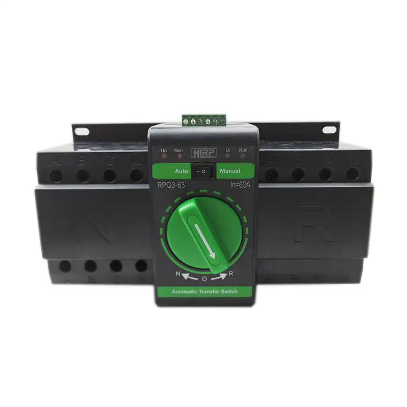
Compact Automatic Transfer Switch
A compact switching direction for smaller distribution boards, equipment panels and limited installation spaces where automatic and manual transfer functions are required.
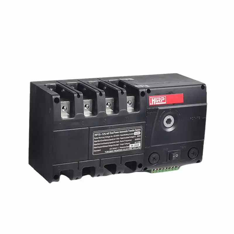
RP7S Automatic Transfer Switch
A molded-case automatic transfer direction for industrial and commercial distribution where current range, poles, short-circuit data and controller functions must be coordinated.
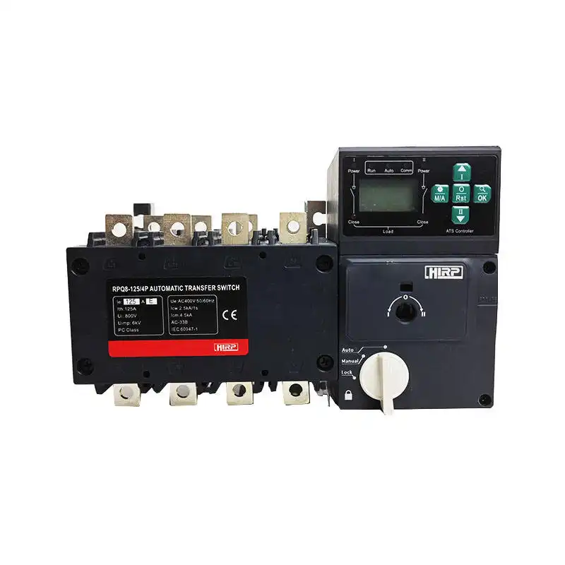
RPQ8 Automatic Transfer Switch
An industrial ATS direction with a visible controller interface for projects that need configurable source monitoring, delays, operating modes and status review.
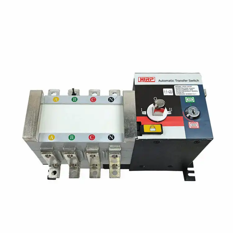
Generator Automatic Transfer Switch
A generator-oriented ATS direction for monitoring the normal source, issuing generator start contacts, verifying standby power and controlling transfer and retransfer.
Confirm these requirements before choosing an ATS model
A useful ATS inquiry describes the complete power system, not only the load current. These nine items reduce revisions and help identify missing protection or controller requirements.
Source arrangement
Define utility-to-utility, utility-to-generator or another approved dual-source arrangement and identify the preferred source.
Provide the single-line diagramVoltage and frequency
State phase-to-phase and phase-to-neutral voltage, frequency, phase sequence and acceptable source variation.
Confirm both power sourcesCurrent and load type
Provide calculated load current, design margin and whether the load includes motors, transformers, UPS, lighting or mixed equipment.
Check the utilization categoryPoles and neutral
Confirm single- or three-phase conductors, solid or switched neutral, grounding scheme and local electrical requirements.
Do not choose poles from current aloneClass and protection
Specify PC or CB class, available fault current, upstream protective devices and required short-circuit ratings.
Coordinate the complete protection systemTransfer and retransfer logic
Define source-failure delay, generator warm-up, transfer delay, normal-source return delay and generator cool-down.
Use controller-specific timing rangesController functions
List voltage/frequency sensing, phase-loss detection, auto/manual modes, test function, alarms and status indication.
Match functions to operating procedureRemote interfaces
Confirm generator dry contact, fire input, common alarm, source position outputs, remote control and communication protocol.
Provide the I/O list or BMS requirementInstallation and environment
State open or enclosed supply, mounting, cable direction, dimensions, ambient temperature, altitude, pollution and enclosure rating.
Provide panel space and destination countryConfigure the sequence around the actual standby source
Controller features and timing ranges vary by model. Establish the intended operating sequence first, then confirm that the selected controller provides the required inputs, outputs and adjustable settings.
Match the switch to the distribution system
Poles, neutral treatment and fault-current performance affect system safety and nuisance operation. The project engineer should confirm grounding and protection using the applicable local rules.
| Design item | What must be confirmed | Why it matters | Useful project input |
|---|---|---|---|
| 2-pole configuration | Single-phase conductor arrangement and whether both line and neutral are switched | Determines isolation, conductor routing and compatibility with the grounding scheme | Single-line diagram and source wiring |
| 3-pole configuration | Three switched phase conductors with the neutral handled outside the switching mechanism | Can be appropriate only when the neutral and grounding design allow a solid neutral | Grounding/bonding diagram and local code |
| 4-pole configuration | Three phases plus a fully switched neutral for the specified system | May be required for separately derived sources or particular ground-fault arrangements | Generator bonding and neutral design |
| Rated operational current | Continuous load, diversity, temperature, enclosure, conductor and utilization category | Frame size alone does not confirm suitability for every load or installation condition | Load schedule and design current |
| Short-circuit withstand | Icw/Icm or conditional short-circuit rating and duration for the exact PC-class model | The ATS must coordinate with the available fault current and upstream protection | Fault study and protective-device model |
| Breaking capacity | Applicable breaking data, trip unit and settings for a CB-class arrangement | Protection behavior must match system selectivity and fault-clearing requirements | Protection study and setting schedule |
| Transition method | Open transition, delayed transition, center-off requirement or another specified sequence | Affects interruption, source overlap, inductive loads and operational procedure | Critical-load requirement and sequence of operation |
| Standards and documents | Applicable IEC 60947-6-1 edition, project certificates, test reports and destination requirements | Documentation and ratings can differ by model, production configuration and market | Specification, country and approval list |
Engineering reminder: The ATS should be selected and installed by qualified electrical personnel using the exact product documentation, system study and local electrical requirements.
Define the ATS from the load continuity requirement
Different facilities can use the same basic transfer principle but require very different protection, timing, interfaces, enclosures and maintenance provisions.
Industrial machinery
Transfer control power or selected machine loads while accounting for motors, drives, restart logic and process interruption.
Review load type, restart sequence and utilization categoryCommercial buildings
Support emergency distribution for lighting, pumps, communication, security and selected building systems.
Review load priority, fire interface and BMS pointsGenerator backup systems
Monitor utility power, command the generator controller and manage transfer, retransfer and cool-down timing.
Review genset start contact and neutral groundingTelecom and infrastructure
Coordinate power continuity for network, signaling, communication and remote-site auxiliary loads.
Review alarms, remote monitoring and environmentData and control systems
Use an ATS as one part of a wider resilience design that may also include UPS, generators and power monitoring.
Review allowable interruption and source coordinationOEM electrical equipment
Integrate a confirmed ATS model, controller settings, labels and wiring interface into repeatable equipment production.
Review drawings, item codes and batch documentationSend the power-system details for an accurate quotation
Provide the available information even if the ATS model is unknown. A single-line diagram, load schedule and controller I/O list can shorten model review.
Describe the sources and load
Voltage, frequency, phase, normal and alternate source, load current, load type and available fault current.
Define switching and control
PC or CB class, poles, neutral, auto/manual mode, delays, generator start, alarms, remote I/O and communication.
Confirm supply details
Open or enclosed form, dimensions, quantity, destination, standards, documents, OEM labels and packaging.
Keep every ATS order aligned with the approved specification
The quotation, drawing, nameplate, controller configuration, accessories and shipment labels should identify the same approved model and project requirements.
Continue planning the complete transfer system
ATS selection questions
Use these answers to prepare the specification before requesting a model or quotation.
How do I choose an automatic transfer switch?
Start with the source arrangement, system voltage and frequency, load current and type, poles, neutral and grounding design. Then confirm PC or CB class, short-circuit coordination, controller sensing, timing, generator interfaces, communication, installation environment, standards and documentation.
What is the difference between PC class and CB class ATS?
PC class transfer switching equipment can make and withstand specified short-circuit currents but is not intended to break them, so it requires coordinated upstream protection. CB class equipment is intended to make, withstand and break short-circuit currents and includes overcurrent releases. Always use exact model data.
Should I choose a 3-pole or 4-pole ATS?
The choice depends on whether the neutral must remain solidly connected or be switched. A switched neutral may be required for separately derived sources or certain ground-fault arrangements. The system grounding design and local electrical rules should determine the pole configuration.
Can an ATS start a standby generator automatically?
A generator-oriented ATS controller can provide a dry contact or specified interface to the generator controller. Confirm contact logic, controller supply, generator warm-up, source-available sensing, retransfer delay and cool-down requirements for the exact model.
How fast should an ATS transfer?
The required transfer time depends on the load and the complete resilience design. Sensitive loads may also require a UPS. Confirm the selected ATS operating time, intentional delays, transition method and total source-restoration sequence rather than relying on one headline switching value.
Does an ATS provide short-circuit and overload protection?
It depends on the ATS class and exact construction. PC class equipment normally relies on coordinated upstream protective devices. CB class equipment includes overcurrent releases and is intended to break short-circuit currents. Verify ratings, settings and selectivity for the complete system.
What controller functions should I specify?
Common requirements include source voltage and frequency monitoring, phase-loss detection, source-failure and restoration delays, automatic and manual modes, generator start output, fire input, source-position outputs, common alarm, remote test and communication. Availability is model-specific.
Can SENTOP supply an enclosed ATS panel?
Open-device or enclosed supply can be reviewed from the project drawing, enclosure dimensions and rating, cable entry, internal protection, meters, indicators, control power, terminal arrangement, destination standards and quantity.
What information should I send for an ATS replacement?
Send the complete model and nameplate, front and rear photos, wiring diagram, voltage, frequency, current, poles, neutral arrangement, dimensions, mounting, controller terminals, upstream protection, load type and required quantity. A sample or original datasheet can improve matching.
Send your single-line diagram, ATS model or project specification
SENTOP can review compact, molded-case, controller-equipped and generator automatic transfer switch requirements for model matching, samples, OEM equipment and bulk orders.
