
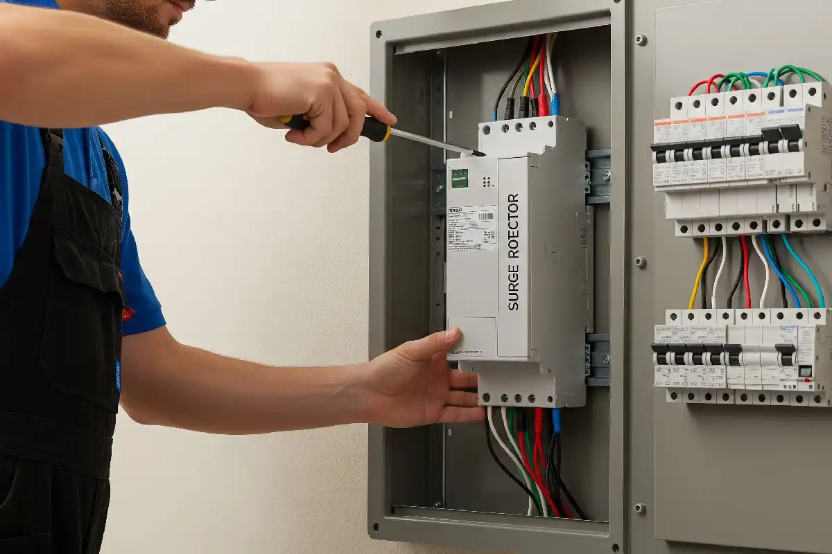
Surge Protection Guide
Surge Protection Guide for a Complete Current Path
Use this surge protection guide to select the SPD type, voltage, protection modes, discharge ratings, backup protection and installation position together. A correct product can still underperform when the earthing path, conductor routing or coordination is wrong.
Answer First
An SPD limits transient voltage by diverting surge current
Surge protection is not simply a device placed anywhere in a panel. The SPD must provide a controlled path from the affected conductors to the equipotential bonding system while keeping the residual voltage at protected equipment within an acceptable coordination design.
Type 1 is the common starting direction where lightning current can enter the installation. Type 2 is the principal distribution-level direction for induced or switching surges. Type 3 is installed near sensitive equipment and coordinated with upstream protection.
Decide whether protection is required
Use the applicable installation rules, risk assessment, external lightning protection, supply arrangement and consequence of equipment failure.
Choose the SPD location and type
Service entrance, main board, subdistribution and equipment zones can require different surge-current duties and coordination.
Match voltage and protection modes
Nominal voltage, maximum continuous voltage and TT, TN or IT topology determine the required connections.
Engineer the installed path
Backup protection, conductor cross-section, route length, bonding, terminal torque and earth arrangement affect real performance.
Interactive Starting Point
Build a practical SPD direction
Choose the installation conditions below. The result prepares a technical enquiry and highlights missing data; it does not replace the applicable risk assessment, wiring rules or exact manufacturer instructions.
Complete the project choices
Planning result only. Confirm the need for protection, exact SPD type, Uc or Ucpv, Up, In, Imax, Iimp, protection modes, short-circuit and follow-current behavior, backup protection, wiring and approvals before ordering.
SPD Type Comparison
Type 1, Type 2 and Type 3 have different test duties
The type designation is not a quality grade. It describes the declared SPD test class and intended position in a coordinated protection concept.
Type 1 SPD
A service-entrance or main-board direction where partial lightning current may enter the electrical installation. Selection is linked to the lightning protection concept and current-sharing assessment.
Type 2 SPD
The principal distribution-board direction for limiting induced lightning surges and switching transients, or for downstream coordination after Type 1 protection.
Type 3 SPD
A fine-protection direction near sensitive equipment. It is normally coordinated with upstream Type 1 or Type 2 protection and is not a substitute for entrance protection where that protection is required.
Combined SPDs: A product marked Type 1+2 or Type 2+3 must have the declared combined test performance for the exact model. A label such as "combined" does not remove the need to verify location, current sharing, Up, backup protection and coordination.
How to Read SPD Ratings
Each symbol answers a different design question
Compare values only when the waveform, protection mode, system voltage and standard definition are the same.
Maximum continuous operating voltage
The maximum RMS AC voltage that may be continuously applied to the SPD's declared mode under specified conditions. Match it to the system topology, voltage tolerance and possible operating conditions.
Voltage protection level
A declared limiting-voltage parameter used for insulation coordination. Review it with equipment impulse withstand, conductor voltage drop and downstream distance.
Nominal discharge current
A declared crest value through the SPD using an 8/20 current impulse for the applicable test duty. It is not the load current carried by the circuit.
Maximum discharge current
A Type 2 declared 8/20 impulse value. Confirm the exact model's test data and do not use Imax alone as a lifetime or site-risk calculation.
Impulse discharge current
A Type 1 declared capability using the 10/350 current impulse. Confirm current sharing and the value per protection mode or pole.
Short-circuit and follow-current behavior
The SPD and required disconnector must be suitable for the prospective short-circuit current and system behavior. Follow-current capability is especially important for voltage-switching technologies.
Temporary overvoltage behavior
TOV is not a short surge. It can arise from system faults or neutral conditions. Verify the SPD's declared response and correct the underlying electrical fault.
Coordinated Protection Zones
Build protection from the entry point to the load
A single SPD cannot automatically protect every board, cable route and electronic interface. Coordination is based on exposure, separation, cable length, equipment withstand and the declared SPD data.
Service entrance
The point where conducted lightning current or utility-side transients can enter the installation.
Common review: Type 1 or Type 1+2, system-specific modes and entrance bonding.Main distribution
Limits residual energy and switching surges while coordinating with the entrance protection.
Common review: Type 2 or coordinated combined SPD.Subdistribution
Long feeders, separate floors, outdoor equipment or another building zone can justify additional protection.
Common review: coordinated Type 2 and local bonding.Sensitive equipment
Control, instrumentation, communication and electronic loads can need local fine protection.
Common review: Type 3 plus signal-line protection where required.The final type and location are determined by the applicable installation rules and lightning protection design. Do not infer a universal distance or device count from this simplified zone map.
System Topology and Installation
The same voltage can require different protection modes
TT, TN-S, TN-C-S and IT systems have different conductor and earth relationships. Select the complete SPD assembly and wiring arrangement for the actual system.
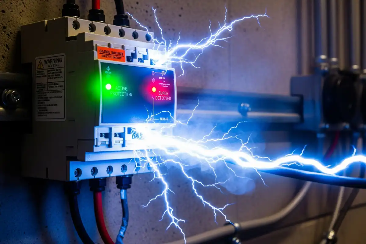
TN systems
Confirm whether the installation is TN-S, TN-C or TN-C-S at the SPD point. Neutral and PE treatment, PEN separation and protection modes must follow the applicable design.
TT systems
Review line-to-neutral and neutral-to-PE protection, earthing conditions and residual-current protection coordination. A 3+1 or 1+1 concept may be selected only where supported by the exact system design.
IT systems
Voltage to earth can change during the first fault. Confirm Uc, insulation monitoring, fault conditions and permitted connection modes for the exact network.
Single or three phase
Do not select module count from phase count alone. Confirm neutral presence, switched conductors, line-line and line-earth voltage, mode ratings and terminal arrangement.
Data and signal lines
Power SPDs do not protect Ethernet, RS485, analog, coaxial or control interfaces. Use interface-compatible signal SPDs with coordinated bonding where required.
Keep conductors short and direct
Avoid loops and unnecessary bends. Route the live-conductor connection and PE/bonding path so the total installed path does not add avoidable inductive voltage.
Follow the declared disconnector data
Use the manufacturer-specified maximum backup fuse or breaker arrangement and verify discrimination, fault current, conductor protection and internal disconnector behavior.
Connect to the correct equipotential point
The PE path, main earthing terminal, enclosure bonding and external lightning protection bonding must be coordinated by the installation design.
Control conductor and torque
Match conductor material and cross-section, terminal capacity, strip length, ferrule requirement and torque. Recheck after transport or panel assembly where required.
Make end-of-life indication visible
Position status windows for inspection, connect remote alarm contacts when required and define a replacement reference for pluggable cartridges.
Record the complete assembly
Keep the SPD model, cartridge, base, backup device, wiring diagram, certificate, test data and inspection interval connected to one approved design.
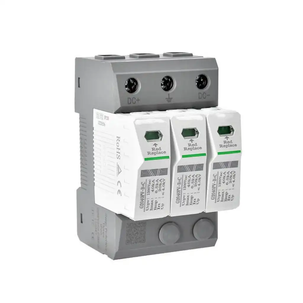
Photovoltaic DC Protection
Use an SPD designed for the PV DC side
PV strings remain energized in daylight and have source behavior that differs from conventional AC systems. An AC SPD must not be substituted for a product evaluated for the PV DC application.
Why Surge Protection Fails
Avoid the installation errors that raise residual voltage
An SPD can show a healthy status window while the protection path, coordination or system selection remains unsuitable.
Uc is wrong for the topology
Too low can expose the SPD to repeated stress or TOV failure; an unnecessarily high value can weaken voltage coordination.
Connection leads are unnecessarily long
Inductive voltage along the leads adds to the voltage protection level seen by downstream equipment.
Type 2 is used where Type 1 duty is required
The product may not be evaluated for the expected lightning-current waveform at the installation entrance.
Backup protection is guessed
An incorrect fuse or breaker can compromise short-circuit safety, availability or conductor protection.
Only the power line is protected
Surges can enter through data, signal, antenna, metallic pipe or another bonded service and damage equipment through interface differences.
Cartridges are not inspected or replaced
Status indication, remote alarm and maintenance records must be part of the operating plan after surge events and during periodic inspection.
Standards Framework
Separate product testing from system installation rules
Product compliance does not automatically prove that the chosen type, location, wiring or coordination is correct for a particular installation.
IEC 61643-11:2025
Requirements and test methods for SPDs connected to AC low-voltage power systems up to the stated scope. It addresses devices intended to limit surge voltages and divert surge currents.
Review IEC scope →IEC 61643-12:2020
Selection, operation, location and coordination principles for SPDs connected to 50/60 Hz AC power circuits and equipment within its scope.
Review IEC scope →IEC 61643-31:2018
Requirements and test methods for SPDs dedicated to the DC side of photovoltaic generators and inverters up to the stated voltage scope.
Review IEC scope →IEC 61643-32:2017
Selection, installation and coordination principles for SPDs used in PV systems, including array, cable, inverter and utility connection considerations.
Review IEC scope →IEC 60364-4-44 and 5-53
Installation requirements for voltage disturbances, device selection, erection, protection, isolation, switching, control and monitoring.
Review IEC 60364-4-44 →IEC 62305-4:2024
Requirements for design, installation, inspection, maintenance and testing of surge protection measures for electrical and electronic systems within structures.
Review IEC scope →SPD RFQ Checklist
Send the system and installation data, not only the SPD type
A one-line diagram, board photo or existing nameplate can shorten model matching. SENTOP can help identify the missing voltage, topology, duty and installation information.
System and exposure
Country and installation rules, AC or DC, nominal and maximum voltage, frequency, TT/TN/IT topology, external LPS, overhead supply and site exposure.
SPD and installation data
Required type, Uc or Ucpv, Up, In, Imax, Iimp, modes, short-circuit current, backup device, conductor route, board location and remote alarm.
Project and order data
One-line diagram, protected equipment, existing model, target certification, quantity, replacement cartridge, labels, documents and delivery destination.
Continue Your Protection Design
Review the related protection range
Surge Protection FAQ
Surge Protection Guide questions buyers ask before choosing an SPD
These answers explain the selection logic. Final design must follow the applicable installation rules and exact product data.
What does a surge protective device do?
An SPD limits transient overvoltage by conducting surge current through a controlled low-impedance path. It does not regulate sustained voltage and does not replace the overcurrent, residual-current or lightning-protection functions required by the installation.
What is the difference between Type 1, Type 2 and Type 3 SPD?
Type 1 is evaluated for lightning-current duty using a 10/350 impulse and is commonly reviewed at the installation entrance. Type 2 is evaluated for distribution surge duty using 8/20 impulses. Type 3 provides coordinated fine protection near equipment. The applicable rules determine the required combination and location.
When is a Type 1 SPD required?
Type 1 is commonly considered where lightning current can enter the installation, including designs with an external lightning protection system or other exposure identified by the applicable assessment. The final requirement and Iimp value come from the lightning and installation design.
Can I install only a Type 2 SPD?
Only when the applicable assessment and installation rules support that direction. A Type 2 SPD is not a substitute for Type 1 duty where lightning current is expected. Long distribution paths or sensitive loads can also require additional coordinated protection.
How do I choose SPD Uc?
Match Uc to the maximum continuous voltage appearing across each protection mode under normal and specified system conditions. Consider nominal voltage, tolerance, TT/TN/IT topology, neutral faults and TOV behavior. Use Ucpv and PV-specific rules on the DC side.
Is a lower Up always better?
A suitably low Up helps insulation coordination, but it is not the only selection factor. Uc, surge-current duty, system faults, technology, lead length, equipment withstand, coordination and product safety must all be satisfied. Installed conductor voltage also contributes to the equipment stress.
What is the difference between In, Imax and Iimp?
In is the nominal discharge current using an 8/20 impulse. Imax is a maximum discharge-current parameter for Type 2 duty using 8/20. Iimp is the Type 1 impulse discharge-current parameter using 10/350. Compare values only under the same definition and protection mode.
Does an SPD need a fuse or circuit breaker?
The exact SPD instructions specify the permitted or maximum backup protection and whether an additional external disconnector is required. Verify prospective short-circuit current, internal disconnection, cable protection and coordination with the selected fuse, MCB or MCCB.
Why should SPD connection wires be short?
Surge current changes rapidly and produces voltage across conductor inductance. Long, looped or indirect connections add voltage to the SPD's declared protection level, increasing the stress seen by protected equipment.
Can an AC SPD be used in a photovoltaic DC circuit?
No, unless the exact product is specifically evaluated and documented for that PV DC duty. PV applications require Ucpv, polarity, DC fault behavior, protection modes and product requirements appropriate to the array and inverter side.
How do I know when an SPD cartridge needs replacement?
Inspect the visual status indicator and any remote alarm contact according to the maintenance plan, especially after known surge events. Replace only with the exact approved cartridge or complete SPD reference specified for the installed base.
What information is needed for an SPD quotation?
Send AC or PV DC application, nominal and maximum voltage, phase and neutral arrangement, TT/TN/IT topology, external lightning protection, SPD location, required type, fault current, backup device, protected equipment, quantity, target market and one-line diagram.
Surge Protection Supply Support
Send the one-line diagram, board photo or existing SPD model
SENTOP can review AC and PV DC surge protection requirements for new panels, replacements, samples, OEM equipment, distributor ranges and bulk orders.
