
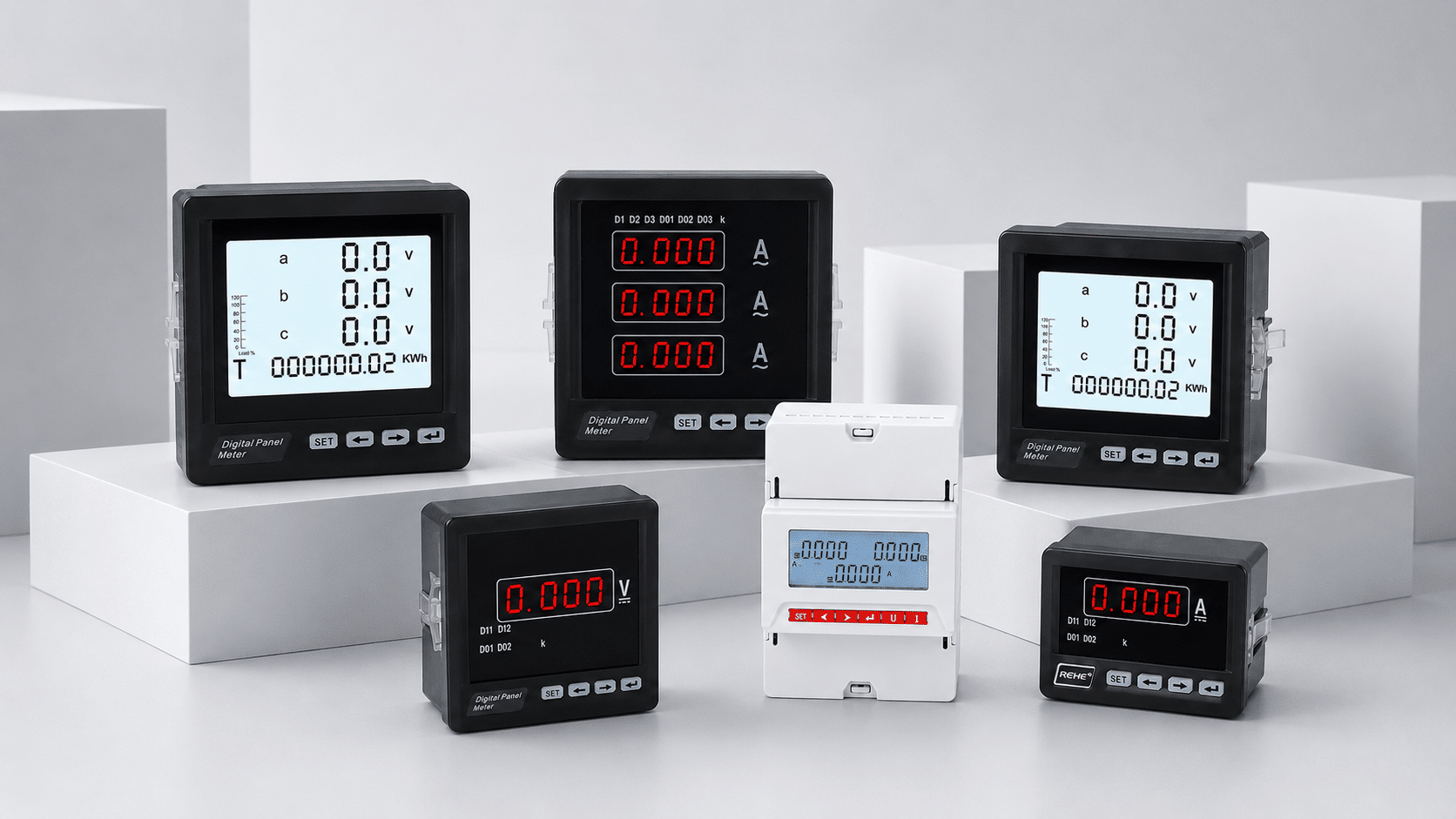
Panel Meter Wiring Guide for Accurate, Stable Readings
Plan the wiring path before connecting a meter. Identify the exact model diagram, auxiliary supply, voltage input, current input, CT or shunt ratio, phase system, polarity, RS485 terminals and protective measures as one complete measurement circuit.
Five checks before a conductor reaches the meter
A panel meter is part of a measurement system. The correct result depends on the instrument, source circuit, sensor ratio, polarity, wiring arrangement and configuration agreeing with each other.
For a replacement, photograph the old meter front, rear terminals, side label and existing wiring before removal. For a new panel, use the one-line diagram and load schedule.
Identify the exact model and suffix
Similar front panels can have different auxiliary supplies, input ranges, terminal positions, communication options and output functions.
Confirm the electrical system
Record AC or DC, frequency, single-phase or three-phase, 3-wire or 4-wire, nominal voltage and the earthing arrangement relevant to the installation.
Separate supply from measurement
Determine whether the meter is self-powered from the measured circuit or needs a separate auxiliary supply. Never assume both terminals serve the same function.
Document CT, VT or shunt data
Match primary and secondary values, rated burden or signal, accuracy, polarity marks and the meter setting used for scaling.
Check protective and installation details
Confirm conductor size, circuit protection, isolation, earthing, clearances, environmental conditions and local wiring requirements.

How a panel meter turns conductors into usable data
The meter does not see the whole installation. It receives selected voltage and current signals, applies the configured ratios and system model, then calculates the values shown locally or sent to a monitoring system.
Electrical potential measured line-to-neutral or line-to-line according to the configured system.
Load current measured directly or reconstructed from a CT or shunt input ratio.
Power performing useful work. Direction and sign depend on correct phase pairing and polarity.
Values used to understand total electrical demand and the reactive component of AC loads.
A relationship between active and apparent power that can expose phase or polarity errors when implausible.
Accumulated energy and system frequency, subject to the exact meter's supported functions and accuracy data.
Understand each circuit before reading terminal numbers
Terminal numbers are model-specific. Use this functional map to understand what must be verified, then transfer that information to the exact diagram supplied with the meter.
Auxiliary supply terminals power the meter electronics
Check the permitted AC or DC supply range, frequency, polarity where applicable, power consumption and whether the supply is isolated from the measured circuit. Apply protection and isolation as required by the product documentation and installation design.
Voltage inputs establish magnitude and phase reference
Match the input to the nominal system voltage and the required single-phase, 3-phase 3-wire or 3-phase 4-wire arrangement. If a voltage transformer is used, the meter ratio and primary/secondary values must agree.
Current inputs must match the source signal and polarity
Current may reach the meter directly, through a current transformer or as a low-voltage signal from a DC shunt. These inputs are not interchangeable. Confirm the input type before energizing.
Communication and outputs require their own documentation
RS485 identifies a physical interface, not the complete data configuration. Confirm protocol, register map, address, baud rate, parity, A/B or D0/D1 labeling, common reference, shield treatment and termination. Relay and analog outputs also have model-specific ratings.
Choose the measurement path from the actual system
These are planning diagrams, not terminal-number instructions. The exact number of inputs, CT arrangement, voltage references and protective components must follow the approved project drawing and the meter manual.
Single-Phase Direct Voltage Measurement
For a compatible meter that measures an approved line-to-neutral or line-to-line voltage directly.
Current Measurement Through a CT
For load current above the meter's direct-input capability or where transformer isolation and standardized secondary current are required.
Three-Phase Multifunction Measurement
For voltage, current, frequency, power, energy and power-factor data from a documented 3-wire or 4-wire system.
DC Current Measurement with a Shunt
For high DC current represented by a specified millivolt signal across a calibrated shunt.

CT and shunt wiring errors can look believable
A reversed sensor, wrong ratio or phase mismatch may still produce a number. The clue often appears in negative power, unrealistic power factor, unequal phases or a value that is consistently scaled by the wrong factor.
A 400/5 CT producing 3.25 A on its secondary represents 260 A on the primary, assuming linear conversion, correct polarity and a compatible 5 A meter input.
A 100 A / 75 mV shunt producing 37.5 mV represents 50 A, assuming the correct shunt, wiring polarity and millivolt input range.
Wire RS485 as a bus, then configure the protocol
Use a trunk or daisy-chain topology with short device connections. Avoid uncontrolled star branches. Confirm the cable, A/B or D0/D1 convention, common reference, shield treatment, line termination, polarization and network limits from the exact equipment documentation.
Every device needs a unique address and compatible baud rate, parity, stop bits, protocol and register map. A correctly wired pair will not communicate if those settings disagree.

Prove the measurement before trusting the data
Work from wiring integrity to configuration, then compare the meter against known operating conditions or an appropriate reference instrument. Treat unexpected readings as evidence to investigate, not values to force with scaling.
Trace the problem without guessing at terminals
Begin with safe isolation and the exact manual. Change one variable at a time and document the result so a wiring fault is not hidden by an incorrect setting.
| Observed symptom | Check first | Likely directions | Useful evidence |
|---|---|---|---|
| Meter display is off | Auxiliary supply at the correct terminals and within rating | Open protection, missing neutral/common, wrong supply type, reversed DC polarity or damaged supply circuit | Supply label, terminal diagram and safely measured supply value |
| Voltage reads zero or incorrectly | Voltage reference, input range and system mode | Missing phase, L-N versus L-L mismatch, VT ratio error, wrong 3P3W/3P4W selection or blown sensing fuse | One-line diagram, phase-to-phase and phase-to-neutral reference readings |
| Current is zero under load | CT secondary continuity and selected input type | CT secondary safely shorted elsewhere, open circuit, wrong channel, no primary conductor through CT or wrong meter mode | CT nameplate, polarity marks, secondary path and load condition |
| Current is consistently scaled wrong | CT or shunt primary/secondary settings | 200/5 entered as 100/5, 1 A versus 5 A mismatch, wrong shunt mV value or direct-input selection | Sensor label and screenshots of meter ratio settings |
| Power is negative or power factor is implausible | CT polarity and phase pairing | Reversed CT, current channel paired with the wrong voltage phase, phase sequence issue or import/export convention | Phase mapping, CT orientation and known load direction |
| RS485 has no response | Interface polarity and serial settings | A/B reversal, duplicate address, wrong baud/parity, star topology, termination issue, unsupported protocol or incorrect register map | Network sketch, device settings and controller request details |
| Reading is unstable or noisy | Terminal security, grounding and cable routing | Loose signal conductor, excess CT burden, shared/shield issue, strong interference, poor auxiliary supply or unsuitable update/filter setting | Panel photos, cable route, load behavior and comparison reading |
Stop and escalate if a CT circuit, hazardous voltage, arc-flash risk, damaged insulation, overheating, unexpected earthing condition or unclear terminal designation is involved.
Use the applicable standard and the model manual together
Standards establish product or system requirements. They do not replace the terminal drawing, ratings, installation instructions or risk assessment for the exact meter and panel.
IEC 61557-12
Requirements for power metering and monitoring devices used to measure electrical quantities in distribution systems.
Review the official IEC scopeIEC 61010-1
General safety requirements for electrical measurement, control and laboratory equipment.
Review the official IEC scopeIEC 61326-1
General EMC requirements for measurement, control and laboratory equipment in industrial and non-industrial locations.
Review the official IEC scopeModbus Serial Line Guide
Official implementation guidance for Modbus communication over serial line, including topology, termination and device documentation.
Open Modbus specificationsExact meter documents
Terminal diagram, rated inputs, auxiliary supply, CT/VT/shunt requirements, communication manual, register map, output ratings and commissioning procedure for the exact model code.
Send the measurement circuit, not only the meter photo
With the system data and wiring evidence, SENTOP can review the product direction, input method, ratio, cutout, communication need and documentation for your project.
Questions installers and buyers ask before commissioning
Use these answers to identify the missing project information, then confirm the final method from the exact product and installation documents.
Can I use one generic wiring diagram for all digital panel meters?
No. Terminal numbers, supply ranges, input types, phase arrangements and optional functions vary by model and suffix. Use a generic guide only to understand the circuit concept, then follow the diagram supplied for the exact meter.
Does a panel meter need a separate auxiliary power supply?
Some meters use a separate auxiliary supply while others may be powered from the measured circuit. Confirm the exact model label and manual. Treat supply terminals and measurement terminals as different circuits unless the documentation explicitly states otherwise.
When should I use a current transformer with a panel meter?
Use a CT when required by the current level, isolation method, system design or meter input specification. Match the CT primary/secondary ratio, 1 A or 5 A secondary where applicable, burden, accuracy and polarity to the meter and application.
What happens if a CT is wired backwards?
Current magnitude may still appear reasonable, but power direction, phase angle, power factor and energy calculations can be wrong. Verify CT orientation, secondary polarity and voltage/current phase pairing.
Why must an energized CT secondary not be open-circuited?
An open CT secondary can develop a hazardous voltage and may damage equipment. Isolate the primary or use the approved shorting and test arrangement before disconnecting the secondary circuit. Qualified personnel should follow the CT and installation safety procedure.
Can the same meter support both 3-phase 3-wire and 3-phase 4-wire systems?
Only when the exact model documentation lists both arrangements. The terminal use, number of sensor inputs and calculation method may differ. Select the correct system mode and follow the matching diagram.
Is RS485 polarity always labeled A positive and B negative?
No. Device labeling conventions can differ. Follow the D0/D1 or A/B definitions in the manuals for every connected device. If communication fails, verify polarity, common reference, serial settings, topology, termination and protocol.
Why does the meter show negative power?
Common directions include reversed CT polarity, current inputs paired with the wrong voltage phases, phase-sequence mismatch or an intentional export condition. Compare the wiring and known power-flow direction before changing settings.
Can a digital panel meter prove that power is off?
No. Do not use the panel meter display as proof of isolation. Follow the approved safe-work procedure and use a properly rated voltage-sensing device to verify the absence of voltage.
What information should I send for wiring support?
Send the exact model code, front and rear photos, terminal diagram, one-line diagram, AC/DC and phase system, voltage, CT/VT/shunt details, auxiliary supply, communication needs, existing readings, quantity and destination market.
Need the meter, sensor ratio and wiring method reviewed together?
Send the one-line diagram, exact model or target measurements, CT/VT/shunt data, panel cutout and communication requirement for a more useful product-matching discussion.
