SENTOP Navigation - Focused Product Menu
SENTOP Electrical Co., Ltd | Low Voltage Electrical Equipment Manufacturer OEM/ODM Support | Bulk Supply | Global Shipping

Spring Terminal Blocks Manufacturer

SPRING CONNECTION TECHNOLOGY BY SENTOP

Reliable Spring Terminal Block Manufacturer

SENTOP supplies spring terminal blocks for fast, organized, and space-efficient wiring in control panels, electrical cabinets, automation equipment, machinery, and industrial power systems. Our product range includes spring feed-through terminals, push-in terminals, protective earth terminals, multi-level terminals, and matching DIN rail accessories.

Faster Wiring Efficient spring-clamp connection for repeated installation work
Compact Installation Suitable for high-density DIN rail terminal strip layouts
Complete Product Range Feed-through, PE, multi-level, markers, bridges, and accessories
Model Matching Support Match products from models, photos, dimensions, or BOM lists
Get a Fast Quote
Send your model, wire size, quantity, photo, drawing, or BOM
Spring Feed-Through Push-In Connection PE Ground Terminals DIN Rail Accessories
SPRING TERMINAL BLOCKS Complete DIN Rail Wiring Range
Feed-Through Conductor connections
PE Grounding Protective earth terminals
Accessories Bridges and markers
COMPLETE SOURCING SUPPORT From Individual Terminal Blocks to Complete Terminal Strip Kits
OEM
Spring Connection Efficient conductor clamping
DIN Rail Mounting Control panel integration
Accessory Matching Plates, bridges, and markers
Bulk Supply Mixed models and OEM packing
COMPLETE SPRING CONNECTION PRODUCT RANGE

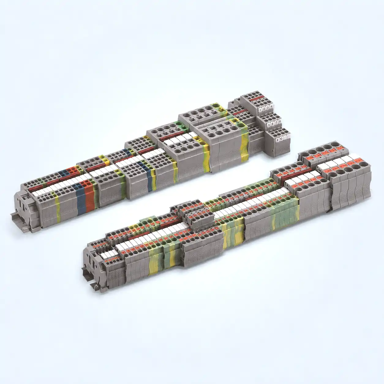
Spring Terminal Block Product Range

SENTOP supplies spring terminal blocks for normal circuit wiring, protective grounding, high-density installation, signal distribution, testing, and complete DIN rail terminal-strip assembly. Product selection should be based on the terminal function, conductor type, wire size, connection method, DIN rail profile, and required accessories.

Feed-Through
01
STANDARD CIRCUIT CONNECTION

Spring Feed-Through Terminal Blocks

Spring feed-through terminal blocks connect an incoming conductor to an outgoing conductor through an internal conductive path. They are suitable for organized power, signal, control, and automation wiring on DIN rails.

  • Conductor-to-conductor circuit connection
  • Suitable for repeated control-panel wiring
  • Compact terminal-strip installation
  • Compatible marker and bridge options
Typical Uses PLC wiring, relays, sensors, actuators and control circuits
Push-In
02
FAST CONDUCTOR INSERTION

Push-In Spring Terminal Blocks

Push-in spring terminal blocks are designed to simplify conductor insertion and reduce repetitive wiring time. Direct insertion capability depends on the selected terminal model, conductor construction, and conductor preparation.

  • Efficient wiring for repeated production
  • Suitable for selected rigid conductors
  • Supports selected ferruled conductors
  • Model-dependent tool operation
Selection Note Confirm solid, stranded, flexible or ferruled conductor requirements
PE Ground
03
PROTECTIVE EARTH CONNECTION

Spring Ground Terminal Blocks

Spring ground terminal blocks connect protective earth conductors to the compatible grounded DIN rail. They are used alongside normal spring feed-through terminals to complete the PE wiring structure of a terminal strip.

  • Protective earth conductor connection
  • DIN rail grounding-foot structure
  • Clear PE circuit identification
  • Model and rail compatibility matching
Important Ground terminals perform a different function from standard feed-through terminals
Multi-Level
04
HIGH-DENSITY WIRING

Double-Level Spring Terminal Blocks

Double-level spring terminal blocks increase connection density by placing two wiring levels within one terminal position. They are suitable for control cabinets where DIN rail length is limited.

  • Two connection levels in one position
  • Reduces required DIN rail length
  • Supports organized signal wiring
  • Separate marking for each connection level
Typical Uses Compact PLC cabinets, sensor wiring and signal distribution
Functional
05
TESTING & CIRCUIT ISOLATION

Functional Spring Terminal Options

Functional spring terminal options can support circuit disconnection, testing, measurement, component integration, or potential distribution. Available functions depend on the selected terminal series and product model.

Disconnect
Test
Distribution
Switching
Availability Confirm the required function, circuit layout and available model
Accessories
06
COMPLETE TERMINAL STRIP SUPPORT

Spring Terminal Block Accessories

Correctly matched accessories complete the fixing, insulation, marking, separation, and potential-distribution structure of the spring terminal strip.

End Brackets
End Plates
Partitions
Markers
Jumpers
DIN Rails
Compatibility Accessories should be selected according to the exact terminal series
PRODUCT FUNCTION OVERVIEW

Select the Product Type According to the Wiring Function

Normal Circuit Wiring Spring feed-through terminal blocks
Fast Repetitive Wiring Push-in spring terminal blocks
Protective Grounding Spring PE ground terminal blocks
High-Density Installation Double-level spring terminal blocks
Testing or Isolation Functional spring terminal options
Complete Strip Assembly Plates, brackets, markers and jumpers
PRODUCT SELECTION REMINDER

Similar Spring Terminal Blocks May Use Different Connection Methods

Spring cage, push-in, tool-operated, multi-level, ground, and functional terminals can differ in conductor range, insertion method, terminal width, DIN rail foot, bridge pitch, marker system, and accessory compatibility. Confirm the exact model and conductor requirements before ordering.

Terminal Function Conductor Type Wire Size Accessory Match
COMPLETE DIN RAIL WIRING SOLUTION

Complete Spring Terminal Strip Solutions

SENTOP can supply spring terminal blocks together with protective earth terminals, end brackets, end plates, partition plates, jumpers, markers, and DIN rails as one coordinated terminal-strip solution. The complete assembly can be organized according to circuit function, conductor size, terminal quantity, grounding positions, marking requirements, and project BOM.

COMPLETE ASSEMBLY Spring Terminal Strip System
Complete DIN Rail System
Connection Spring feed-through terminals
Grounding Protective earth terminals
Accessories Brackets, plates and markers

One Coordinated System for Wiring, Grounding and Identification

A complete terminal strip is more than a group of individual spring terminal blocks. Each component performs a specific electrical, mechanical, insulation, or identification function. Correct model matching helps simplify installation and reduce accessory compatibility problems.

01

Spring Feed-Through Terminals

Connect incoming and outgoing conductors for power, signal, control, sensor, and automation circuits.

02

Spring Ground Terminals

Connect protective earth conductors to the compatible grounded DIN rail through the PE contact structure.

03

End Brackets

Secure both ends of the assembled terminal group and prevent sideways movement along the DIN rail.

04

End and Partition Plates

Close exposed terminal sides and separate circuit groups, voltage levels, or electrical functions.

05

Jumpers and Bridges

Electrically connect selected terminal positions and distribute a common potential across circuits.

06

Markers and Labels

Identify terminal positions, wire numbers, circuit functions, cabinet groups, and maintenance information.

TERMINAL STRIP ASSEMBLY SEQUENCE

Typical Component Order on a DIN Rail

The final sequence depends on the panel wiring diagram, grounding positions, circuit separation, bridge layout, and terminal identification requirements.

01

Start End Bracket

Fixes the beginning of the terminal strip.

02

Feed-Through Terminals

Complete the main circuit connection positions.

03

Ground Terminals

Add protective earth positions where required.

04

Partitions and Plates

Separate circuit functions and close open sides.

05

Markers and Bridges

Add identification and common-potential connections.

06

Final End Bracket

Secures the completed terminal strip.

TERMINAL STRIP CONFIGURATIONS

Common Spring Terminal Strip Combinations

01

Standard Control Wiring Strip

Spring feed-through terminals combined with end brackets, end plates, markers, and selected bridge accessories.

Feed-Through Markers Bridges
02

Wiring and Grounding Strip

Feed-through and protective earth terminals arranged according to equipment and cabinet grounding positions.

Feed-Through PE Ground End Plates
03

High-Density Signal Strip

Multi-level spring terminals used to increase wiring density where the available DIN rail length is limited.

Multi-Level Signal Wiring Markers
04

Potential Distribution Strip

Selected terminal positions connected by compatible jumpers to distribute a common electrical potential.

Jumpers Distribution Partitions
PROJECT INFORMATION

Details Required to Prepare a Complete Terminal Strip

A clear BOM, wiring diagram, terminal list, or cabinet layout helps organize the correct terminal models and accessory quantities.

Conductor Size Required wire range in AWG or mm²
Terminal Quantity Number of positions for each function
Grounding Positions Required PE terminal locations
Bridge Layout Common-potential connection positions
Separation Points Locations requiring partition plates
Marking Information Terminal numbers and circuit labels
DIN Rail Type Required rail profile and length
Order and Packaging Kit quantity and grouping requirements
COMPONENT COMPATIBILITY

Complete the Terminal Strip with Series-Matched Accessories

Similar-looking spring terminals, ground terminals, end plates, jumpers, and markers may use different side profiles, terminal widths, bridge pitches, marker slots, or DIN rail mounting structures. Confirm the terminal series and product model before preparing the complete assembly.

Terminal Series Terminal Width Bridge Pitch Marker System

Explore 1,000+ More SENTOP Models

Can't find the exact terminal block for your specific project? We offer a vast range of specialized connection solutions and customized OEM options to meet every industrial requirement.

Get Full E-Catalog Technical Support Available 24/7
SPRING CONNECTION WORKING PRINCIPLE

How Spring Terminal Blocks Create a Reliable Connection

Spring terminal blocks use a spring-clamping mechanism to hold the conductor against the internal conductive part. Depending on the terminal design and conductor type, the wire may be inserted directly or installed after opening the spring with an operating tool.

CONNECTION PROCESS

Four Steps from Conductor Insertion to Spring Clamping

The exact operating method depends on whether the selected product uses spring-cage, push-in, push-button, or tool-operated spring connection technology.

01
ACTIVATE THE SPRING

Open the Clamping Position

For tool-operated models, insert a suitable operating tool into the designated opening to move the spring and create space for the conductor.

Push-in models may not require this step for selected conductors.
02
INSERT THE CONDUCTOR

Place the Wire into the Terminal

Insert the prepared conductor into the correct wire-entry position until it reaches the required connection depth.

Confirm the stripping length and conductor preparation.
03
RELEASE THE SPRING

Allow the Spring to Clamp the Wire

Remove the operating tool or release the push button so the spring applies clamping force to the conductor.

The spring mechanism maintains pressure on the conductor.
04
VERIFY THE CONNECTION

Check the Final Wire Position

Confirm that the conductor is fully inserted, firmly held, correctly identified, and not exposing excessive bare wire.

Follow the product specification and installation instructions.
SPRING CONNECTION TYPES

Spring Cage and Push-In Connection Methods

Both technologies use spring force, but the conductor insertion method and required operation can differ according to the terminal structure and conductor type.

01
TOOL-OPERATED SPRING CONNECTION

Spring Cage Terminal Blocks

Spring cage terminal blocks normally use an operating tool or push button to open the spring before the conductor is inserted. After the operating mechanism is released, the spring clamps the wire against the conductive part.

Suitable for multiple conductor types
Controlled wire insertion process
Convenient conductor removal
Operating method depends on the model
02
DIRECT INSERTION TECHNOLOGY

Push-In Spring Terminal Blocks

Push-in terminals may allow selected rigid conductors or ferruled flexible conductors to be inserted directly. Flexible conductors without suitable preparation may still require spring activation with a tool or push button.

Supports faster repetitive wiring
Direct insertion for selected conductors
Suitable for production wiring
Conductor compatibility must be confirmed
CONNECTION CHARACTERISTICS

Why Spring Clamping Is Used in Industrial Wiring

Efficient Wiring Process Spring connection technology can reduce repetitive installation steps in production and panel wiring.
Consistent Spring Force The spring mechanism applies clamping pressure without requiring the installer to set a screw-tightening torque.
Standardized Installation The connection process is less dependent on differences in manual screw-tightening habits.
Compact Terminal Layout Spring terminal designs can support organized and high-density wiring in limited cabinet space.
Convenient Maintenance Conductors can be disconnected and reconnected using the operating mechanism provided by the terminal.
Complete System Integration Feed-through, ground, multi-level, bridge, marker, and accessory options support complete terminal strips.
CONDUCTOR COMPATIBILITY

Confirm the Conductor Type Before Selecting the Connection Method

Direct insertion and tool requirements can change according to the conductor construction, cross-section, ferrule, stripping length, and selected spring terminal model.

Solid Conductors

Selected push-in models may support direct insertion when the solid conductor meets the specified wire range and preparation requirements.

Model-dependent direct insertion

Stranded Conductors

Stranded conductors may require the spring to be opened before insertion, depending on conductor stiffness and terminal design.

Check the conductor construction

Flexible Conductors

Flexible wires commonly require tool-assisted spring activation unless they are prepared with a suitable ferrule for the selected terminal.

Tool operation may be required

Ferruled Conductors

Properly crimped ferrules can simplify conductor insertion, but ferrule dimensions and wire range must match the terminal specification.

Confirm ferrule and terminal size
INSTALLATION CHECKLIST

Check These Details Before Energizing the Circuit

Correct Terminal Model Confirm function, wire range, and connection type.
Correct Stripping Length Follow the selected terminal specification.
No Damaged Conductor Check strands, ferrules, and conductor condition.
Full Wire Insertion Confirm the conductor reaches the intended position.
No Excess Bare Wire Avoid exposed conductive material outside the terminal.
Spring Fully Released Ensure the operating mechanism returns correctly.
Secure DIN Rail Mounting Check the terminal foot and end bracket positions.
Correct Circuit Marking Verify terminal numbers, PE positions, and labels.
IMPORTANT CONNECTION NOTE

Not Every Spring Terminal Supports Tool-Free Direct Insertion

Spring cage, push-in, push-button, and tool-operated terminal blocks use different conductor insertion methods. Direct insertion depends on the selected product model, conductor construction, conductor cross-section, and wire preparation. Always confirm the product specification before installation.

Terminal Model Conductor Type Wire Range Insertion Method
CONNECTION TECHNOLOGY COMPARISON

Spring Terminal Blocks vs. Screw Terminal Blocks

Spring and screw terminal blocks are both widely used in industrial control panels, electrical cabinets, automation machinery, and power distribution equipment. The correct connection technology depends on conductor type, installation speed, cabinet space, maintenance requirements, operator procedures, and applicable project standards.

01
SPRING CONNECTION TECHNOLOGY

Spring Terminal Blocks

Spring terminal blocks use a spring mechanism to hold the conductor against the internal conductive part. Depending on the model, the conductor may be inserted directly or installed after opening the spring with a tool or push button.

Efficient for repetitive panel wiring
No manual screw-tightening torque setting
Suitable for compact terminal-strip layouts
Connection method depends on conductor type
02
TRADITIONAL SCREW CONNECTION

Screw Terminal Blocks

Screw terminal blocks use a screw-clamp structure to secure the conductor. The installer inserts the prepared wire and tightens the screw according to the applicable product instructions and project procedure.

Familiar connection method for many installers
Suitable for many general industrial circuits
Clear visual and mechanical tightening process
Correct tightening procedure must be followed
TECHNICAL AND INSTALLATION COMPARISON

Key Differences Between Spring and Screw Connections

Comparison Factor Spring Terminal Blocks Screw Terminal Blocks Selection Consideration
Connection Method The conductor is held by a spring-clamping mechanism. The conductor is held by a screw-operated clamp. Select according to the preferred installation method and existing cabinet standard.
Installation Procedure Direct insertion or tool-assisted insertion, depending on the model and conductor. Insert the conductor and tighten the screw according to the specified procedure. Confirm conductor preparation, stripping length, and operating requirements.
Repetitive Wiring Speed Can support efficient repetitive wiring, especially with compatible push-in designs. Each connection normally requires a separate screw-tightening step. Consider production volume, labor procedure, and installation time.
Operator Consistency Spring force is provided by the terminal mechanism. Connection quality depends on correct screw tightening and installation practice. Standardized work instructions remain important for both technologies.
Tool Requirements Some models support direct insertion, while others require a tool or push button. A suitable screwdriver or torque-controlled installation tool is normally required. Do not assume every spring terminal is completely tool-free.
Conductor Compatibility Depends on whether the conductor is solid, stranded, flexible, or ferruled. Depends on the clamp design, conductor type, and wire preparation. Confirm the supported conductor range for the selected model.
Terminal Density Available in compact and multi-level designs for high-density wiring. Compact options are also available, depending on the screw terminal series. Calculate complete terminal-strip width rather than comparing one terminal only.
Maintenance Access Conductors can be released through the terminal operating mechanism. Conductors are removed by loosening the screw clamp. Consider cabinet access, service frequency, and technician familiarity.
Retightening Procedure Spring clamping does not use a manually tightened connection screw. Inspection or retightening practices depend on the project, product, and maintenance procedure. Follow the product documentation and applicable maintenance rules.
Replacement Projects Suitable when converting to spring connection after dimensional and functional confirmation. Often preferred when maintaining an existing screw-terminal system. Check width, height, rail foot, accessories, and wiring procedure before replacement.
Accessory Compatibility Requires matching end plates, bridges, markers, and brackets for the spring terminal series. Requires accessories matched to the selected screw terminal family. Similar-looking accessories are not automatically interchangeable.
Typical Applications Automation equipment, production wiring, compact control panels, and signal circuits. General industrial wiring, traditional panels, replacement projects, and established systems. Both technologies can be suitable when correctly selected for the application.
CONNECTION SELECTION FACTORS

Six Questions to Ask Before Choosing the Terminal Technology

The connection type should be selected as part of the complete panel design rather than according to one product feature alone.

01

What Conductor Type Is Used?

Confirm solid, stranded, flexible, or ferruled conductors and the required AWG or mm² range.

02

How Important Is Wiring Speed?

High-volume production may place greater emphasis on repeatable and efficient conductor installation.

03

How Much DIN Rail Space Is Available?

Compare terminal width, number of positions, accessories, partitions, and complete strip length.

04

How Will the Equipment Be Maintained?

Consider conductor replacement frequency, cabinet access, technician tools, and maintenance procedures.

05

What Standards Must Be Followed?

Confirm the project requirements, terminal specifications, documentation, and applicable installation rules.

06

Must It Match an Existing System?

Replacement projects may require matching terminal shape, DIN rail foot, bridge system, and marking accessories.

APPLICATION-BASED SELECTION

When Each Connection Technology May Be More Suitable

Consider Spring Terminal Blocks When

  • The project includes high-volume repetitive wiring.
  • Consistent spring clamping is preferred over manual screw-tightening.
  • Compact or multi-level terminal arrangements are required.
  • Sensors, actuators, PLCs, and automation circuits require organized wiring.
  • Conductors may need convenient release and reconnection.

Consider Screw Terminal Blocks When

  • The customer must maintain an existing screw-terminal system.
  • Installers are already trained around screw connection procedures.
  • Replacement accessories and existing cabinet layouts are based on a screw terminal family.
  • The project specification explicitly requires a screw-clamp connection.
  • Traditional industrial wiring procedures are preferred.
MIXED CONNECTION SYSTEMS

One Control Cabinet Can Use More Than One Terminal Technology

Some projects use spring terminal blocks for signal and automation wiring while retaining screw terminals for other circuit groups. A mixed system can be organized when the terminal functions, conductor requirements, DIN rail space, accessories, and project standards are clearly defined.

Signal and PLC Wiring Spring terminal blocks for compact, repeated connections
Power Circuit Groups Connection type selected according to circuit requirements
Protective Grounding Dedicated PE terminals matched to the terminal system
Unified Identification Consistent terminal numbers, markers, and circuit labels
SELECTION REMINDER

Neither Connection Technology Is Automatically Right for Every Project

Spring terminal blocks can improve repetitive wiring efficiency, while screw terminal blocks remain suitable for many traditional and replacement applications. Final selection should be based on conductor type, electrical requirements, installation method, DIN rail space, maintenance procedure, accessories, and applicable project documentation.

Conductor Type Wiring Process Panel Space Project Standard
CUSTOMER WIRING CHALLENGES

Common Wiring Problems Solved by Spring Terminal Blocks

Industrial control-panel projects often involve repetitive wiring, limited DIN rail space, multiple conductor types, maintenance requirements, and complex accessory lists. Correctly selected spring terminal blocks can simplify the wiring process, but the terminal function, conductor, installation method, and accessories must still be matched carefully.

01
WIRING EFFICIENCY

Slow Repetitive Panel Wiring

Large control panels may contain hundreds of repeated conductor connections. A time-consuming installation process can increase assembly labor and extend the production schedule.

Customer Impact Longer assembly time, inconsistent production speed, and higher labor requirements.
Spring Terminal Solution Push-in or tool-operated spring connections can simplify repeated conductor installation when matched to the correct wire type.
02
INSTALLATION CONSISTENCY

Different Manual Tightening Results

Screw-terminal installation can depend on the operator, screwdriver, tightening procedure, and project work instructions. Differences between operators may affect installation consistency.

Customer Impact Additional inspection, operator training, and tightening procedure control.
Spring Terminal Solution The spring mechanism supplies the clamping force, reducing dependence on manually applied screw torque.
03
LIMITED CABINET SPACE

Insufficient DIN Rail Installation Space

Compact electrical cabinets may not have enough rail length for all required feed-through, grounding, signal, and distribution connections.

Customer Impact Crowded layouts, difficult wire routing, and limited space for future circuit expansion.
Spring Terminal Solution Compact and multi-level spring terminal blocks can increase connection density within the available space.
04
EQUIPMENT MAINTENANCE

Frequent Conductor Replacement

Sensors, actuators, switches, motors, and field devices may require replacement or rewiring during equipment maintenance and commissioning.

Customer Impact Longer service time, difficult terminal access, and increased risk of reconnecting the wrong circuit.
Spring Terminal Solution The operating mechanism can support controlled conductor release and reconnection during maintenance.
05
CIRCUIT IDENTIFICATION

Unclear Terminal and Wire Identification

A terminal strip without organized markers, circuit numbers, grouping, and separation can be difficult to inspect, commission, and maintain.

Customer Impact Slower troubleshooting, wiring mistakes, and more time required to identify circuit functions.
Spring Terminal Solution Compatible markers, partition plates, and terminal groups create a clearer and more organized wiring system.
06
ACCESSORY COMPATIBILITY

Incorrect Plates, Bridges or Markers

Accessories from different spring terminal families may have similar appearances but use different widths, profiles, bridge pitches, marker slots, and mounting structures.

Customer Impact Delayed assembly, incompatible components, incomplete terminal strips, and repeat purchasing.
Spring Terminal Solution Match every accessory according to the exact terminal series, model, dimensions, and required function.
PROBLEM-TO-SOLUTION PROCESS

Four Steps to Build the Correct Spring Terminal Block Solution

Selecting the terminal according to its appearance alone can lead to conductor, rail, and accessory compatibility problems. Start with the circuit function and complete the selection step by step.

01
IDENTIFY FUNCTION

Define the Circuit Requirement

Confirm whether the connection requires feed-through, protective earth, multi-level, disconnect, test, or potential-distribution functions.

02
CONFIRM CONDUCTOR

Check Wire Type and Size

Provide the conductor cross-section and identify whether the wire is solid, stranded, flexible, or prepared with a ferrule.

03
MATCH THE MODEL

Select the Terminal Series

Compare the connection method, terminal width, DIN rail foot, dimensions, conductor range, and project electrical requirements.

04
COMPLETE THE BOM

Add All Required Accessories

Confirm end brackets, end plates, partitions, markers, jumpers, DIN rails, terminal quantities, and packaging requirements.

PROJECT DIAGNOSIS

Information That Helps Identify the Correct Solution

Existing Product Photos Front, side, top, wire entry, and DIN rail foot views.
Reference Model Existing terminal number, label, or customer item code.
Product Dimensions Terminal width, height, length, and mounting profile.
Conductor Information Wire size, conductor type, ferrule, and stripping method.
DIN Rail Profile Existing rail structure, dimensions, and installation space.
Wiring Function Feed-through, PE, bridging, testing, or signal distribution.
Accessory Requirements Plates, brackets, markers, jumpers, and separation points.
Quantity and Packaging Sample demand, batch quantity, BOM kits, and label format.
WIRING CHALLENGE MAPPING

Match the Customer Problem with the Correct Product Direction

Customer Problem Recommended Product Direction Additional Items to Confirm
Repeated wiring takes too long Push-in or efficient tool-operated spring terminals Conductor type, ferrule, stripping length, and insertion method
DIN rail space is limited Compact or double-level spring terminal blocks Total terminal quantity, terminal width, and accessory space
Grounding positions are unclear Dedicated spring protective earth terminals Rail compatibility, PE positions, and grounding structure
Common potential requires repeated wires Compatible jumpers or bridging accessories Bridge pitch, pole quantity, and connected terminal positions
Maintenance takes too much time Spring terminals with an accessible operating mechanism Cabinet access, wire release method, and circuit marking
Accessories do not fit Series-matched end plates, markers, and bridges Exact model, side profile, width, slot, and mounting method
IMPORTANT SELECTION REMINDER

Solve the Wiring Problem Before Selecting the Terminal Appearance

A spring terminal block should be selected according to its electrical function, conductor range, connection technology, terminal width, DIN rail compatibility, maintenance method, and accessory system. Similar-looking terminals may not solve the same wiring problem or accept the same accessories.

Wiring Function Conductor Type Panel Space Accessory System
SPRING TERMINAL BLOCK SELECTION GUIDE

How to Select the Right Spring Terminal Block

Selecting spring terminal blocks requires more than matching product appearance. The terminal function, conductor type, wire size, spring connection method, electrical requirements, DIN rail profile, terminal dimensions, and accessory system should be confirmed before ordering.

01
TERMINAL FUNCTION

Define the Required Circuit Function

Start by confirming what the terminal must do inside the control panel or electrical cabinet.

Feed-Through Protective Earth Double-Level Disconnect Test Distribution
02
CONNECTION TECHNOLOGY

Confirm the Spring Connection Method

Spring terminal blocks may use different conductor insertion and release mechanisms.

Spring Cage Push-In Push Button Tool Operated
03
CONDUCTOR INFORMATION

Identify the Wire Type and Size

Provide the conductor cross-section in AWG or mm² and confirm the conductor construction.

Solid Stranded Flexible Ferruled AWG mm²
04
PROJECT REQUIREMENTS

Confirm Electrical and Project Conditions

Check the required current, voltage, insulation, documentation, and applicable project standards for the selected model.

Current Voltage Insulation Documentation
05
DIN RAIL COMPATIBILITY

Match the Mounting Rail and Terminal Foot

Confirm the DIN rail profile, available mounting space, terminal foot structure, and installation orientation.

Rail Profile Rail Size Mounting Foot Installation Space
06
TERMINAL DIMENSIONS

Calculate the Complete Terminal Strip Width

Include terminal width, number of positions, end plates, partitions, ground terminals, and end brackets.

Width Height Length Total Positions
07
PROTECTIVE GROUNDING

Define the PE Terminal Positions

Confirm the number, location, conductor size, rail compatibility, and terminal family of all protective earth connections.

PE Quantity PE Position Grounding Foot Rail Contact
08
ACCESSORY SYSTEM

Complete the Terminal Accessory List

Select accessories according to the exact spring terminal series rather than appearance alone.

End Brackets End Plates Partitions Markers Jumpers DIN Rails
QUICK SELECTION TABLE

Match the Application with the Correct Terminal Direction

Application Requirement Recommended Terminal Direction Information to Confirm
Standard conductor connection Spring feed-through terminal blocks Wire size, conductor type, current, voltage, width, and accessory family
Fast repeated panel wiring Push-in spring terminal blocks Direct insertion capability, conductor stiffness, ferrule, and stripping length
Protective earth connection Spring ground terminal blocks DIN rail compatibility, grounding foot, conductor size, and PE positions
Limited DIN rail space Compact or double-level spring terminals Total positions, terminal height, marking access, and complete strip width
Common-potential distribution Spring terminals with compatible jumpers Bridge pitch, pole quantity, terminal positions, and circuit layout
Circuit testing or isolation Disconnect or test terminal options Required function, operating method, test point, and available product model
Existing terminal replacement Equivalent spring terminal model matching Existing model, product photos, dimensions, wire range, rail foot, and accessories
Complete terminal strip supply Terminal blocks plus matched accessories BOM, quantities, PE positions, bridges, markers, partitions, and packaging
STEP-BY-STEP SELECTION PATH

Follow This Order to Reduce Model-Matching Errors

Starting with the wiring function helps prevent selecting a product that looks correct but uses the wrong conductor range, mounting structure, or accessory system.

01

Define the Function

Feed-through, PE, multi-level, disconnect, test, or distribution.

02

Confirm the Conductor

Wire size, wire construction, ferrule, and stripping requirements.

03

Select the Connection

Spring cage, push-in, push-button, or tool-operated connection.

04

Check Rail and Space

DIN rail profile, terminal dimensions, and complete strip length.

05

Complete Accessories

Plates, brackets, bridges, markers, partitions, and rails.

INFORMATION FOR MODEL MATCHING

Send These Details for a More Accurate Recommendation

Existing Model Reference number or customer item code
Product Photos Front, side, top, and rail-foot views
Dimensions Width, height, length, and side profile
Conductor Details AWG or mm², wire type, and ferrule
Project Requirements Required current, voltage, and standards
DIN Rail Type Rail profile and available installation space
Accessory List Brackets, plates, markers, and jumpers
Order Quantity Samples, batch orders, or annual demand
SPRING TERMINAL BLOCK MODEL SUPPORT

Need Help Matching a Spring Terminal Block?

Send the existing model, product photos, terminal dimensions, conductor size, DIN rail type, required function, accessory list, and order quantity. SENTOP will review the information and help organize a suitable product direction.

Request Model Matching Photos, drawings, specifications and BOM files are accepted
FINAL SELECTION REMINDER

Confirm Model Specifications Before Final Installation

Conductor range, current, voltage, stripping length, terminal dimensions, connection method, DIN rail compatibility, and accessory matching vary by product model. Final selection should be checked against the applicable product documentation and project requirements.

Model Data Wire Range Rail Profile Accessories
COMPLETE DIN RAIL ACCESSORY SYSTEM

Spring Terminal Block Accessories

A complete spring terminal strip requires correctly matched fixing, insulation, separation, identification, and potential-distribution accessories. SENTOP supplies end brackets, end plates, partition plates, markers, jumpers, bridges, and DIN rails for compatible spring terminal block systems.

01
TERMINAL STRIP FIXING

DIN Rail End Brackets

End brackets are installed at both ends of the terminal group to secure spring terminal blocks and prevent sideways movement on the DIN rail.

  • Fixes the terminal group in position
  • Supports stable panel installation
  • Used at both ends of the strip
  • Must match the selected DIN rail
Main Function Mechanical fixing and terminal-strip support
02
OPEN-SIDE INSULATION

Terminal Block End Plates

End plates close the open side of selected spring terminal blocks and complete the insulation structure at the end of a terminal group.

  • Covers exposed terminal sides
  • Completes the insulation structure
  • Creates a clean terminal-strip finish
  • Must match the terminal side profile
Main Function Insulation closure and terminal-group finishing
03
CIRCUIT SEPARATION

Partition and Separator Plates

Partition plates divide terminal groups with different circuit functions, electrical potentials, voltage levels, or wiring classifications.

  • Separates different circuit groups
  • Improves terminal-strip organization
  • Supports required electrical spacing
  • Helps identify functional sections
Main Function Circuit separation and functional grouping
04
CIRCUIT IDENTIFICATION

Markers and Terminal Labels

Markers identify terminal numbers, wire numbers, circuit functions, equipment positions, and maintenance information inside electrical cabinets.

  • Terminal position identification
  • Wire and circuit numbering
  • Supports inspection and maintenance
  • Available with project-based information
Main Function Clear identification and wiring management
05
POTENTIAL DISTRIBUTION

Jumpers and Bridging Accessories

Compatible jumpers electrically connect selected adjacent spring terminal blocks and distribute a common potential across multiple connection points.

  • Connects selected terminal positions
  • Distributes a common electrical potential
  • Reduces repeated external wiring
  • Available for different pole quantities
Main Function Common-potential connection and distribution
06
MOUNTING FOUNDATION

DIN Rails

DIN rails provide the mounting foundation for spring feed-through terminals, protective earth terminals, end brackets, and related cabinet components.

  • Supports terminal block installation
  • Available in different rail profiles
  • Can be prepared to project length
  • Must match the terminal mounting foot
Main Function Terminal mounting and cabinet integration
ACCESSORY FUNCTION OVERVIEW

Five Functions Required for a Complete Spring Terminal Strip

Each accessory performs a different role in the mechanical, electrical, insulation, or identification structure of the completed DIN rail terminal strip.

Fixing End brackets hold the assembled terminal group securely on the rail.
Insulation End plates close open terminal sides and complete the housing structure.
Separation Partition plates divide circuit functions and terminal groups.
Distribution Jumpers connect terminal positions with a common electrical potential.
Identification Markers organize terminal numbers, wires, and circuit information.
ACCESSORY MATCHING PROCESS

Select the Main Terminal Before Selecting Accessories

01

Confirm the Terminal Model

Identify the exact spring terminal series, model, connection function, and housing structure.

02

Check the Terminal Profile

Confirm width, height, side profile, bridge channel, marker slot, and mounting foot.

03

Define the Accessory Function

Determine whether the accessory is required for fixing, insulation, separation, marking, or bridging.

04

Confirm Compatibility

Verify the accessory model, quantity, installation position, and terminal-family compatibility.

ACCESSORY COMPATIBILITY CHECKLIST

Information to Confirm Before Ordering

Terminal Series Exact spring terminal product family
Terminal Model Product number or reference model
Terminal Width Width and total terminal-strip length
Side Profile Housing shape and open-side structure
Bridge Pitch Terminal spacing and bridge positions
Marker Slot Marker format and installation position
DIN Rail Type Rail profile and mounting dimensions
Required Quantity Accessory quantity for each terminal strip
COMPLETE ACCESSORY BOM

Typical Items Included in a Spring Terminal Strip BOM

The exact quantity depends on the wiring diagram, terminal grouping, grounding positions, bridge layout, and marking requirements.

Component Typical Function Information Required
Spring Terminal Blocks Circuit connection, grounding, testing, or distribution Model, function, wire size, and quantity
End Brackets Secures the terminal group on the DIN rail DIN rail type and number of terminal strips
End Plates Closes exposed terminal sides Terminal model and open-side positions
Partition Plates Separates voltage levels or circuit functions Separation positions and terminal profile
Jumpers and Bridges Distributes a common electrical potential Bridge pitch, pole quantity, and connected positions
Markers Identifies terminal numbers and circuit functions Marker format, text, numbering, and quantity
DIN Rail Provides the mounting foundation Rail profile, material, length, and quantity
ACCESSORY COMPATIBILITY

Similar-Looking Spring Terminal Accessories May Not Be Interchangeable

End plates, partitions, markers, jumpers, and end brackets can differ in terminal profile, mounting structure, bridge pitch, marker slot, height, width, and product-family compatibility. Select accessories according to the exact spring terminal series and model rather than appearance alone.

Exact Series Side Profile Bridge Pitch Marker Format
INDUSTRIAL WIRING APPLICATIONS

Spring Terminal Blocks for Industrial Applications

Spring terminal blocks are used in control panels, automation machinery, electrical cabinets, building systems, energy equipment, transportation infrastructure, and industrial production equipment. The correct terminal type should be selected according to the circuit function, conductor, installation density, maintenance method, and applicable project requirements.

01
CONTROL PANEL WIRING

Industrial Control Panels

Spring terminal blocks organize incoming power, control signals, relay circuits, PLC wiring, sensor connections, and protective grounding inside industrial control panels.

PLC input and output wiring Relay and contactor circuits Signal and control connections Protective earth terminal groups
Selection Focus Terminal function, wire size, circuit marking, bridge layout, and total DIN rail space
02
MACHINE AUTOMATION

Automation Machinery

Automated machinery often contains repeated connections for sensors, actuators, motors, switches, valves, and control devices that must be clearly organized and accessible.

Sensor and actuator wiring Limit switch connections Motor-control signal wiring Repeated production assembly
Selection Focus Wiring speed, conductor type, maintenance access, terminal density, and machine BOM
03
ELECTRICAL DISTRIBUTION

Electrical Cabinets

Electrical cabinets may require separate terminal groups for incoming circuits, control power, signal distribution, auxiliary wiring, grounding, and outgoing equipment connections.

Incoming and outgoing circuits Auxiliary control power Common-potential distribution Circuit separation and marking
Selection Focus Electrical requirements, terminal grouping, partition positions, accessories, and documentation
04
BUILDING CONTROL SYSTEMS

Building Automation

Building-control cabinets connect heating, ventilation, lighting, access, monitoring, elevator, and energy-management devices through organized control and signal circuits.

HVAC control wiring Lighting-control circuits Monitoring and alarm signals Field-device connections
Selection Focus Signal density, terminal identification, field wiring, maintenance access, and cabinet layout
05
ENERGY EQUIPMENT

Renewable Energy Systems

Spring terminal blocks can be used in control and auxiliary circuits within energy-storage cabinets, inverters, monitoring equipment, charging systems, and renewable-energy control units.

Monitoring and control circuits Sensor and communication wiring Auxiliary equipment connections Protective earth organization
Selection Focus Circuit function, conductor range, insulation, project standards, grounding, and cabinet conditions
06
TRANSPORTATION CONTROL

Transportation and Infrastructure

Transportation and infrastructure projects use terminal blocks in control cabinets, signaling equipment, monitoring systems, station equipment, roadside devices, and auxiliary circuits.

Signaling and control wiring Monitoring-device connections Infrastructure control cabinets Organized maintenance circuits
Selection Focus Project specifications, documentation, installation environment, maintenance method, and approval requirements
APPLICATION CIRCUIT FUNCTIONS

Common Terminal Functions Across Industrial Equipment

A single cabinet may use multiple spring terminal block types according to the electrical function of each circuit group.

Feed-Through Wiring Connects incoming and outgoing conductors for normal power, signal, and control circuits.
Protective Grounding Connects PE conductors to the compatible grounded DIN rail structure.
High-Density Wiring Uses compact or multi-level terminals when the available DIN rail length is limited.
Potential Distribution Uses matched jumpers to distribute a common potential across selected terminal positions.
Testing and Isolation Uses functional terminals where circuit testing, disconnection, or isolation is required.
Circuit Identification Uses markers and partitions to organize circuit numbers, functions, and terminal groups.
APPLICATION MATCHING GUIDE

Select the Terminal Direction According to the Wiring Scenario

Application Scenario Recommended Product Direction Important Details to Confirm
PLC and relay control circuits Spring feed-through terminal blocks Wire size, conductor type, terminal width, marker system, and bridge requirements
High-volume machinery wiring Push-in or efficient tool-operated spring terminals Conductor preparation, direct-insertion capability, ferrules, and assembly procedure
Compact signal cabinets Compact or double-level spring terminals Total positions, terminal height, cabinet clearance, and marking access
Equipment protective grounding Spring protective earth terminals Grounding positions, conductor size, DIN rail compatibility, and terminal family
Shared control potential Spring terminals with compatible jumpers Bridge pitch, pole quantity, circuit positions, and separation requirements
Maintenance and test circuits Disconnect or test spring terminal options Required function, operating method, test access, and available model
PROJECT REQUIREMENTS

Application Information Required Before Product Selection

Industrial application names alone are not enough to select a terminal model. The actual wiring and project conditions should be reviewed before preparing the product list.

Electrical Requirements Required current, voltage, insulation, and circuit function
Conductor Information Wire size, conductor construction, ferrule, and stripping length
DIN Rail Structure Rail profile, available length, mounting position, and clearance
Cabinet Space Terminal width, number of positions, and complete strip dimensions
Maintenance Method Conductor replacement, test access, technician tools, and procedures
Project Documentation Applicable standards, specifications, drawings, and approval needs
Accessory System End plates, brackets, partitions, markers, bridges, and rails
Supply Format Individual models, mixed BOM, assembled kits, labels, and packaging
APPLICATION SELECTION WORKFLOW

From Equipment Type to Complete Terminal Strip

01

Define the Equipment

Identify the cabinet, machine, system, or infrastructure application.

02

Separate Circuit Functions

Divide normal wiring, grounding, testing, and distribution circuits.

03

Confirm Conductors

Check wire sizes, conductor types, ferrules, and quantities.

04

Match Terminal Models

Select the connection type, dimensions, and DIN rail structure.

05

Complete the BOM

Add terminals, PE positions, markers, bridges, plates, and brackets.

APPLICATION SELECTION REMINDER

Industry Name Alone Does Not Determine the Correct Terminal Model

Two machines in the same industry may use different conductor sizes, circuit functions, DIN rails, cabinet layouts, maintenance procedures, accessories, and project standards. Final spring terminal block selection should be based on the actual wiring requirements and product documentation.

Circuit Function Wire Information Cabinet Layout Project Standard
MANUFACTURING AND SUPPLY SUPPORT

SENTOP as Your Spring Terminal Block Manufacturer

SENTOP supports industrial customers with spring terminal blocks, protective earth terminals, multi-level terminals, matching DIN rail accessories, model identification, mixed-product BOM supply, OEM labeling, and project-based packaging. Product selection is organized according to the actual conductor, circuit function, terminal dimensions, DIN rail, and accessory requirements.

SPRING TERMINAL BLOCK SUPPLY Production, Assembly and Order Preparation
Manufacturer Support
Product Supply Multiple terminal functions
BOM Support Terminals and accessories
Order Preparation Labels and packaging

From Individual Models to Complete Spring Terminal Strip Kits

Customers may require one replacement model, several terminal sizes, or a complete DIN rail terminal-strip BOM. SENTOP can organize the product list according to the required functions, conductor sizes, grounding positions, bridge layouts, marking information, quantities, and packaging method.

Model Identification Review existing models, photos, dimensions, rail feet, and accessory structures.
Equivalent Product Matching Compare function, conductor range, dimensions, installation method, and accessory compatibility.
Complete BOM Organization Combine spring terminals, PE terminals, brackets, plates, markers, jumpers, and DIN rails.
Mixed-Model Supply Prepare multiple models and accessories within one coordinated industrial order.

Replacement matching should be confirmed according to the actual terminal function, conductor, electrical requirements, dimensions, DIN rail structure, and applicable project documentation.

MANUFACTURER CAPABILITIES

Spring Terminal Block Supply for Different Project Requirements

01

Multiple Product Functions

Supply options can include spring feed-through terminals, protective earth terminals, multi-level terminals, and available functional terminal models.

02

Conductor-Based Matching

Product recommendations can be organized according to conductor size, conductor construction, ferrule use, and required insertion method.

03

Accessory System Support

Match end brackets, end plates, partitions, markers, jumpers, bridges, and rails to the selected terminal family.

04

OEM Labeling and Packaging

Support project-based product labels, customer item codes, quantity labels, grouped packing, and outer-carton information.

05

Sample and Bulk Orders

Support product evaluation, project samples, batch purchasing, mixed-model orders, and recurring supply plans.

06

Export Order Preparation

Organize model separation, quantity verification, accessory grouping, carton labeling, and shipment documentation according to the order.

FLEXIBLE SUPPLY FORMATS

Select the Supply Format That Matches Your Project

Customers can purchase individual products, mixed-model BOMs, accessory packages, or grouped terminal-strip kits according to the project installation and inventory method.

FORMAT 01

Individual Terminal Models

Separate spring terminal block models supplied according to the required product number and quantity.

Single Model Replacement Stock Supply
FORMAT 02

Mixed-Model Project BOM

Multiple terminal types, sizes, colors, grounding models, and accessories organized within one order.

Mixed Models Multiple Sizes One Order
FORMAT 03

Terminal and Accessory Packages

Main terminal blocks supplied together with matching brackets, plates, markers, jumpers, and DIN rails.

Terminals Accessories Complete List
FORMAT 04

Project-Grouped Kits

Products grouped according to cabinet number, machine, terminal strip, production batch, or customer item code.

Grouped Packing Project Labels Kit Supply
COOPERATION PROCESS

From Product Information to Order Preparation

Clear product and project information helps reduce model mismatching and incomplete accessory lists.

01

Send Requirements

Provide models, photos, drawings, conductor sizes, quantities, specifications, or BOM files.

02

Review and Match

Compare terminal function, dimensions, wire range, DIN rail structure, and accessory system.

03

Confirm Product List

Finalize terminal models, accessory quantities, labels, packaging, and order requirements.

04

Prepare the Order

Organize production or supply, model separation, quantity checks, packing, and shipment preparation.

SPRING TERMINAL BLOCK MANUFACTURER SUPPORT

Looking for a Spring Terminal Block Manufacturer?

Send your existing model, product photos, conductor size, terminal function, DIN rail profile, accessory list, required quantity, and packaging requirements. SENTOP will help review the information and organize a suitable supply solution.

Model Matching Mixed BOM Supply Accessory Support OEM Packaging
Send Your Requirements Models, photos, drawings and BOM files are accepted
PRODUCT INSPECTION AND ORDER VERIFICATION

Quality Control for Spring Terminal Blocks

Spring terminal block quality control should cover the housing, spring-clamping mechanism, conductive components, conductor entry, operating structure, DIN rail mounting foot, terminal dimensions, accessory compatibility, product identification, quantity, and packaging information before shipment.

QUALITY INSPECTION Spring Terminal Block Verification
Inspection Process
Appearance Housing and component condition
Dimensions Model and profile verification
Function Connection and mounting checks

Verify the Terminal, Accessories and Order Information

Product inspection is not limited to checking the plastic housing. The spring mechanism, conductor entry, internal conductive parts, operating structure, rail mounting foot, terminal dimensions, model identification, and matched accessories should also be reviewed.

Visual Inspection Check housing condition, color, markings, deformation, cracks, and visible assembly defects.
Spring Structure Check Review the spring position, operating movement, conductor opening, and component assembly.
Dimensional Verification Compare terminal width, height, length, rail foot, and side profile with the model data.
DIN Rail Installation Check Confirm that the terminal mounts correctly on the intended compatible DIN rail profile.

Inspection methods and acceptance requirements should be organized according to the selected product model, customer specification, project documentation, and order scope.

QUALITY CONTROL CHECKPOINTS

Key Areas to Inspect on Spring Terminal Blocks

01

Plastic Housing

Check the housing for cracks, deformation, abnormal color, incomplete molding, contamination, and visible damage.

02

Spring-Clamping Mechanism

Inspect the spring position, return movement, operating structure, conductor opening, and visible assembly condition.

03

Conductive Components

Review the position and visible condition of the internal conductive part and connection structure.

04

Conductor Entry

Check the wire-entry opening, conductor path, operating hole, push button, and connection-point identification.

05

Operating Structure

Confirm that the tool opening or push-button mechanism moves correctly and returns to the intended position.

06

DIN Rail Mounting Foot

Inspect the mounting profile, locking structure, housing condition, and compatibility with the intended rail.

07

Grounding Structure

For PE terminal models, check the grounding-foot structure, rail-contact area, housing identification, and product model.

08

Terminal Dimensions

Verify width, height, length, side profile, bridge pitch, marker position, and other model-related dimensions.

09

Accessory Compatibility

Check whether end plates, brackets, markers, jumpers, and partitions match the selected terminal family.

10

Model Identification

Confirm model number, product color, customer item code, label information, and packaging identification.

11

Quantity Verification

Compare product quantities, accessory quantities, mixed-model lists, and package counts with the order.

12

Packaging Information

Check product separation, inner labels, quantity labels, customer codes, carton information, and packing condition.

QUALITY CONTROL PROCESS

Typical Inspection Steps Before Shipment

The exact process may vary according to the terminal model, order quantity, customer requirements, accessory list, and packaging method.

01

Review Order Information

Confirm model numbers, colors, quantities, accessories, labels, and packaging requirements.

02

Inspect Product Appearance

Check housing condition, visible assembly, identification, and component completeness.

03

Verify Dimensions and Fit

Review product dimensions, rail mounting, accessory fit, and model-related profiles.

04

Check Connection Operation

Review the spring opening, conductor insertion, release movement, and final connection condition.

05

Verify Packing and Quantity

Check product separation, quantity, labels, accessory groups, cartons, and order completeness.

INSPECTION REFERENCE

Product Area, Inspection Purpose and Verification Method

Inspection Area Main Purpose Typical Verification Direction
Housing and Appearance Identify visible damage, molding defects, contamination, or incorrect product color. Visual inspection and comparison with the approved model or order information.
Spring and Operating Mechanism Check the movement and visible condition of the conductor-clamping structure. Operating check using the intended terminal opening or push-button method.
Conductor Entry Confirm that the wire-entry position and connection path are complete and unobstructed. Visual review and model-based conductor insertion check where required.
DIN Rail Mounting Confirm the mounting foot matches the intended DIN rail profile and installation method. Installation and removal check on a compatible rail.
Terminal Dimensions Confirm the terminal matches the required model, panel space, and accessory system. Dimensional measurement and comparison with the selected product data.
Accessories Prevent mismatched end plates, brackets, markers, bridges, or partitions. Physical fit review and terminal-family matching.
Model and Quantity Confirm the correct products and quantities are prepared for the order. Compare model labels, packing lists, quantities, and mixed-model BOMs.
Packaging Protect the products and keep models, quantities, and project groups organized. Check inner packing, labels, carton condition, and order separation.
ORDER COMPLETENESS CHECK

Verify Products and Accessories as One Complete Order

Main Terminal Models Feed-through, PE, multi-level or functional models
Required Colors Verify product colors and functional identification
Accessory Models Plates, brackets, markers, jumpers and rails
Product Quantities Check every terminal and accessory quantity
Product Labels Model, quantity, customer code and package information
Project Grouping Cabinet, machine, terminal strip or BOM separation
Inner Packaging Product protection and model separation
Outer Cartons Carton condition, labels, quantities and shipment marks
QUALITY CONTROL REMINDER

Inspection Requirements Should Match the Actual Product and Project

Different spring terminal block models may use different connection mechanisms, conductor ranges, terminal dimensions, DIN rail feet, grounding structures, accessories, and packaging methods. Inspection items should be confirmed according to the selected model, order specification, and customer requirements.

Product Model Connection Structure Accessory Match Order Information
PACKAGING AND COMPLETE KIT SUPPLY

Organized Packaging for Spring Terminal Block Orders

Spring terminal block orders may include multiple terminal models, protective earth terminals, end brackets, end plates, partition plates, markers, jumpers, DIN rails, and customer-specific labels. SENTOP can organize products according to model, quantity, project, cabinet, machine, or terminal-strip requirements.

ORDER PACKAGING Terminal Blocks and Matching Accessories
Organized Supply
Model Separation Different products packed clearly
Quantity Check Products checked against the BOM
Project Grouping Cabinet or machine-based supply

Packaging Arranged Around Your Purchasing and Assembly Process

Customers can purchase individual terminal models, mixed-model orders, matching accessories, or complete terminal-strip kits. Packaging can be arranged according to customer codes, product models, production batches, cabinet numbers, machine numbers, or specific BOM requirements.

Separate Model Packaging Different terminal and accessory models remain clearly identified within mixed-product orders.
Package Identification Labels can include model, quantity, customer code, project number, and package information.
Project-Based Grouping Products can be grouped by cabinet, machine, terminal strip, BOM, or installation stage.
Order Completeness Check Terminal models, accessories, quantities, labels, and packaging groups are checked before shipment.

Custom labels, barcodes, customer item codes, project kits, mixed-model packages, and special packing quantities should be confirmed before order preparation.

AVAILABLE SUPPLY FORMATS

Packaging Options for Different Order Structures

01
STANDARD PRODUCT SUPPLY

Individual Model Packaging

One terminal or accessory model is packed according to the confirmed quantity and standard label information.

Single Model Quantity Label Standard Packing
02
MIXED PRODUCT ORDERS

Mixed-Model Packaging

Multiple terminal sizes, functions, colors, and accessories are separated and identified within the same order.

Mixed Models Clear Separation One Shipment
03
TERMINALS AND ACCESSORIES

Complete BOM Packaging

Main terminals, PE terminals, brackets, plates, markers, jumpers, and rails are prepared according to the BOM.

Complete BOM Accessory Match Quantity Check
04
PROJECT-SPECIFIC SUPPLY

Cabinet or Machine Kits

Products are grouped according to cabinet, machine, terminal strip, installation area, or customer item code.

Project Kits Grouped Labels Assembly Support
COMPLETE TERMINAL STRIP KIT

Typical Components Included in a Project Kit

The final kit content depends on the wiring diagram, conductor sizes, terminal quantities, grounding positions, bridge layout, separation points, marker system, and DIN rail requirements.

Feed-Through Terminals Standard circuit connection terminals in the required sizes and quantities.
Protective Earth Terminals PE terminals prepared according to the required grounding positions.
End Brackets Brackets used to secure completed terminal groups on the DIN rail.
End Plates Matched plates used to close the open sides of selected terminal models.
Partition Plates Separators used between circuit groups or different terminal functions.
Jumpers and Bridges Compatible accessories used for common-potential distribution.
Terminal Markers Numbering and identification items prepared according to the project.
DIN Rails Compatible mounting rails prepared according to the required profile and length.
PACKAGE LABEL INFORMATION

Identification That Can Be Added to Each Package

Product Model Terminal or accessory reference number
Package Quantity Quantity contained in each package
Customer Item Code Customer purchasing or inventory code
Project or BOM Number Reference for project-based order management
Cabinet Number Identification for a specific electrical cabinet
Machine Number Product grouping for equipment assembly
Terminal Strip Number Identification for a specific terminal group
Package Sequence Package number within a grouped order
ORDER PACKAGING PROCESS

From Confirmed BOM to Shipment Preparation

Packaging is organized after the product list, quantities, labels, grouping method, and delivery requirements have been confirmed.

01

Review the Order List

Confirm models, quantities, colors, accessories, project groups, and packaging instructions.

02

Separate Product Models

Organize terminals and accessories according to model, function, color, and quantity.

03

Apply Package Labels

Add model, quantity, customer code, project, cabinet, or package identification.

04

Complete Inner Packing

Protect products and keep different models, accessories, and project groups separate.

05

Prepare Outer Cartons

Complete carton identification, quantity checking, packing review, and shipment preparation.

PACKAGING REQUIREMENT GUIDE

Match the Order Type with the Appropriate Supply Method

Order Situation Recommended Packaging Method Information to Confirm
One standard terminal model Standard model-based packaging Model, color, quantity, package quantity, and label information
Multiple terminal models Separate mixed-model packaging Model list, quantity per model, colors, and separation requirements
Terminals and accessories Complete BOM packaging Terminal models, brackets, plates, markers, jumpers, DIN rails, and quantities
Multiple electrical cabinets Cabinet-number grouping Cabinet number, product list, quantities, labels, and package sequence
Machine production kits Machine-based kit packaging Machine number, BOM, batch quantity, customer codes, and assembly sequence
Customer inventory system Customer-code labeling Customer item codes, barcode format, quantity format, and label layout
SHIPMENT PREPARATION

Packaging Checks Before Shipment

Correct Product Models Products match the confirmed order list
Correct Quantities Package and total quantities are reviewed
Accessory Completeness Brackets, plates, markers, jumpers, and rails are checked
Clear Package Labels Product and project information remains readable
Model Separation Different products remain separated correctly
Inner Product Protection Terminal housings and accessories remain protected
Outer Carton Condition Carton closure, labels, and shipment marks are checked
Packing List Review Shipment contents match the final order record
PACKAGING CONFIRMATION REMINDER

Confirm Special Packaging Requirements Before Order Preparation

Customer codes, custom labels, barcodes, project grouping, cabinet kits, package quantities, accessory sets, and recurring packaging formats should be confirmed before order preparation. Final packaging depends on the product list, order quantity, project structure, and shipment method.

Product List Package Quantity Label Format Project Grouping
SPRING TERMINAL BLOCK FAQ

Frequently Asked Questions About Spring Terminal Blocks

Find answers about spring terminal block operation, conductor compatibility, push-in wiring, DIN rail installation, protective earth terminals, accessories, model matching, mixed BOM orders, and project-based supply.

BEFORE SELECTING A TERMINAL MODEL

Confirm the Wiring Function, Conductor and Installation Structure

Similar-looking terminal blocks may use different conductor ranges, spring mechanisms, dimensions, DIN rail feet, bridge pitches, marker slots, and accessory systems. Final selection should be based on the exact model information and project requirements.

Wire Type Circuit Function DIN Rail Accessories
01 What is a spring terminal block?

A spring terminal block uses a spring-based clamping mechanism to hold the conductor against the conductive component. Depending on the product design, the connection may be operated with a tool, push button, or direct conductor insertion.

02 Are all spring terminal blocks push-in terminals?

No. Spring terminal blocks include several connection structures, such as spring-cage, push-button, tool-operated, and push-in designs. Direct insertion capability depends on the selected terminal model and conductor type.

03 What conductor types can be used?

Compatible conductors may include solid, stranded, flexible, or ferruled wires. The acceptable conductor construction and cross-section vary by terminal model. Check the product data before final installation.

04 Do flexible wires require ferrules?

Ferrule requirements depend on the conductor, terminal design, wiring procedure, and project specification. Flexible conductors may be used with ferrules where required, but the ferrule size and preparation should match the selected product documentation.

05 How do I select the correct wire size?

Confirm the conductor cross-section in AWG or mm², conductor construction, ferrule use, circuit function, and required electrical conditions. Then compare this information with the conductor range of the exact terminal model.

06 Can spring terminals be mounted on any DIN rail?

No. The terminal mounting foot must match the intended DIN rail profile and dimensions. Confirm the rail type, terminal foot, installation orientation, and available cabinet space before ordering.

07 What is a spring protective earth terminal?

A protective earth terminal connects the PE conductor to a compatible grounded DIN rail structure. The grounding foot, wire range, rail profile, terminal family, and required grounding positions should be confirmed.

08 Can jumpers connect several terminal positions?

Compatible jumpers can distribute a common potential across selected terminal positions. The jumper model, bridge pitch, pole quantity, terminal series, and connected positions must match the actual circuit layout.

09 Are accessories from different terminal series interchangeable?

Not necessarily. End plates, partitions, markers, jumpers, and brackets may differ in side profile, width, bridge pitch, marker slot, mounting structure, and terminal-family compatibility. Do not select accessories by appearance alone.

10 Can SENTOP help match an existing terminal model?

Model matching can be reviewed using the existing model number, brand, product photos, terminal dimensions, conductor size, circuit function, DIN rail profile, electrical requirements, and accessory information.

11 Can I order terminal blocks and accessories in one BOM?

Yes. A mixed BOM may include feed-through terminals, protective earth terminals, multi-level models, end brackets, end plates, partitions, markers, jumpers, and compatible DIN rails.

12 What information is required for a quotation?

Provide the product model or photos, circuit function, conductor size and type, required quantities, DIN rail profile, accessory list, electrical requirements, project standards, packaging instructions, and drawings or BOM files where available.

INFORMATION FOR MODEL REVIEW

Details That Help Improve Product Matching

Existing Model Brand, model number or customer item code
Product Photos Front, side, top and mounting-foot views
Dimensions Width, height, length and side profile
Conductor Details AWG or mm², conductor type and ferrule
Circuit Function Feed-through, PE, test, disconnect or distribution
DIN Rail Rail profile and available installation space
Accessories Plates, brackets, markers, jumpers and rails
Order Requirements Quantity, packaging, labels and project standards
TECHNICAL CONFIRMATION

Check the Exact Product Data Before Final Installation

Conductor range, stripping length, connection method, electrical ratings, terminal dimensions, rail compatibility, accessories, and installation procedures vary by model. Final selection and installation should follow the applicable product documentation and project requirements.

Model Data Wire Range DIN Rail Accessories
Scroll to Top