
Fixed Terminal Blocks for Organized Multi-Pole Wiring
SENTOP supplies fixed screw terminal strips with separated poles and transparent protective covers for panels, equipment and power connections. Match the complete strip by electrical rating, conductor, pole count, pitch, mounting centers, dimensions and cover arrangement.
A fixed terminal block is selected as one mechanical and electrical unit
The number of screws is only the visible starting point. Two strips with the same pole count may use different pitch, mounting-hole spacing, conductor capacity, screw hardware, covers and external dimensions.
Match the TB, X3 or X5 direction to the actual installation
The product images organize the available fixed terminal strip directions. Final ratings, pole counts, dimensions and accessories must be confirmed against the selected model.
Do not replace one series with another from appearance alone. Similar housings can have different conductor, pitch, screw and mounting data.
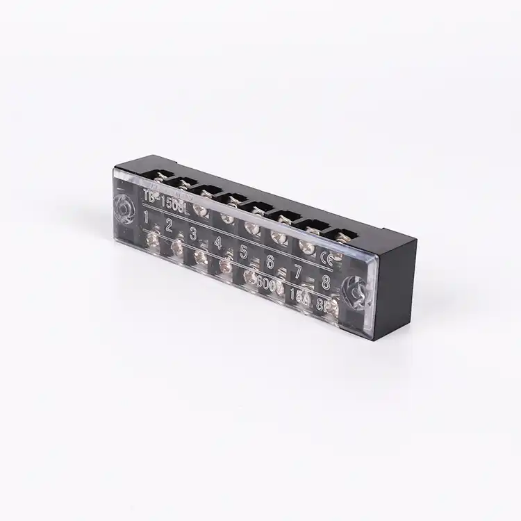
01TB Series Fixed Terminal Blocks
A fixed-base screw terminal strip direction for organized multi-pole connections where circuit separation and a transparent protective cover are required.
- Confirm first
- Rating and wire range
- Mechanical data
- Poles, pitch and hole centers
- Installation
- Panel or equipment base
 02
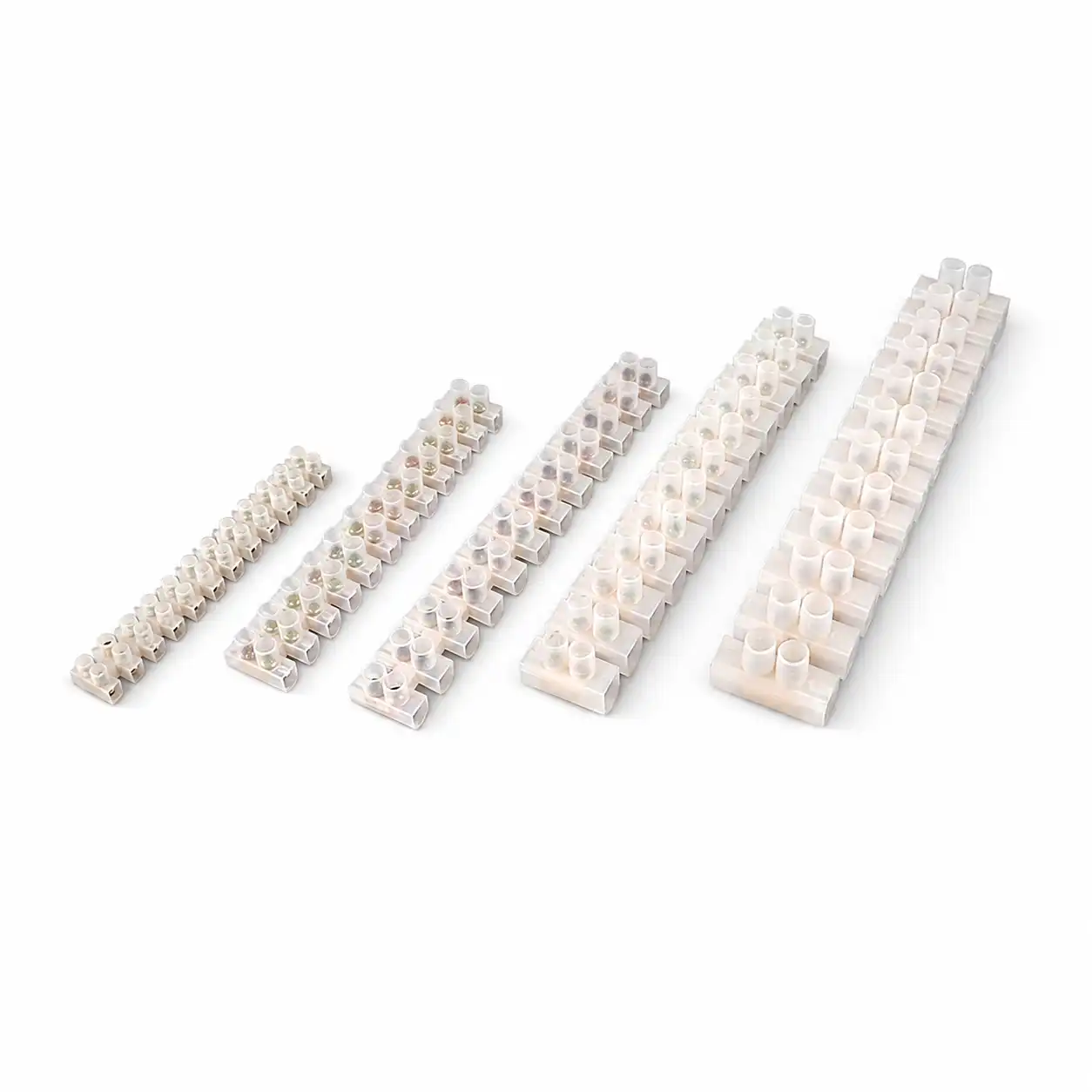
02X3 Series Fixed Terminal Blocks
A compact fixed terminal strip direction for equipment and panel wiring. Match the exact body, pole quantity, conductor entry, cover and mounting footprint.
- Confirm first
- Conductor and circuit duty
- Mechanical data
- Pitch and overall dimensions
- Replacement
- Compare the complete footprint
 03
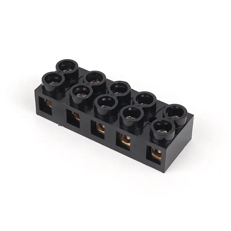
03X5 Series Fixed Terminal Blocks
An additional fixed screw terminal strip direction for projects with different conductor, body and mounting requirements. Confirm the exact model data before design release.
- Confirm first
- Current, voltage and wire
- Mechanical data
- Poles, pitch and cover
- Ordering
- Model, quantity and market
Six checks before a fixed terminal strip enters the BOM
This sequence helps avoid a strip that carries the stated current but cannot accept the conductor, fit the mounting holes or provide the required cover clearance.
Match more than the label and number of poles
A useful replacement review compares the electrical function and the complete mechanical interface. Clear photos beside a ruler or dimension drawing can prevent repeated questions and unsuitable samples.
Where fixed multi-pole terminal blocks fit the wiring architecture
A fixed strip is useful when the equipment design calls for a defined row of screw connections on a stable base rather than a modular DIN rail assembly.
Fixed terminal block support for samples, projects and OEM orders
Commercial details are reviewed together with the model so the approved product, cover, label and packaging remain clear when the order moves into production.
Model and Replacement Matching
Compare ratings, wire interface, positions, pitch, dimensions, mounting centers and cover configuration.
Sample and Drawing Review
Use an approved sample or confirmed technical drawing to establish the project reference before bulk supply.
Label and Packaging Requirements
Discuss eligible model marking, labels, barcodes, inner packaging and carton identification for the order.
Batch and Repeat Orders
Keep the approved model information, quantities, packaging and delivery requirements connected to repeat purchasing.

Required documents, inspection scope, markings and packaging should be stated during quotation. Availability and applicability must be confirmed for the exact fixed terminal block model, rating and target market.
Send the data that determines the complete fixed terminal strip
Use this checklist for a new design, an existing-model replacement or a multi-pole terminal strip quotation.
| Information group | What to provide | Why it changes the model |
|---|---|---|
| Electrical system | AC or DC, voltage, frequency, load current and circuit function | Defines the applicable documented electrical rating and product direction |
| Conductor | Material, cross-section, solid or stranded wire, ferrule or lug and insulation diameter | Changes terminal opening, hardware, stripping and termination compatibility |
| Strip arrangement | Pole count, pitch, spare positions, identification and cover requirement | Determines strip length, terminal spacing and visible circuit organization |
| Mounting | Overall dimensions, hole centers, fastener size, base material and available clearance | Confirms whether the strip fits the existing or planned equipment footprint |
| Compliance | Target market, required standard or approval and model-specific documents | Requirements must be checked against the exact model and rating |
| Commercial scope | Quantity, sample need, label, packaging, destination and requested delivery | Allows a useful quotation and feasibility review for the actual order |
Questions buyers ask before selecting a model
Answers are selection guidance. Final suitability depends on the documented data of the exact product and the complete electrical installation.
What is a fixed terminal block?
A fixed terminal block is a multi-pole connection strip mounted directly to a panel, chassis or equipment base. The TB-style products shown here use separated screw terminals and may include a transparent protective cover. Unlike a modular DIN rail terminal, the positions and base are supplied as one strip.
How is a fixed terminal block different from a DIN rail terminal block?
A fixed terminal strip is mounted through its own base and has a defined pole count and overall footprint. DIN rail terminals are individual modular units clipped to a rail and assembled with series-specific accessories. Choose according to the equipment architecture, service method, expansion needs and approved mechanical design.
How do I choose the correct number of poles?
Count the required isolated circuit positions and add only the spare positions required by the project. Then confirm terminal pitch, total strip length, mounting-hole centers, cover length, identification and space for conductor entry. Pole count alone does not confirm fit.
Can SENTOP help replace an old TB-series terminal block?
Yes, a replacement direction can be reviewed when sufficient information is available. Send the existing model, label, front and side photos, electrical data, pole count, pitch, overall dimensions, mounting-hole centers, wire or lug method and cover details.
When should a transparent protective cover be specified?
A cover can limit casual contact with the connection area and help protect it from dropped hardware or foreign material, but it does not replace the final enclosure or installation safety design. Confirm cover retention, opening method, screw access, labeling visibility, clearance and applicable requirements.
Can fixed terminal blocks be supplied with OEM labels or packaging?
Eligible model labeling, barcodes, inner packaging and carton identification can be reviewed. Provide the exact product, artwork, required content, packaging format, quantity, target market and approval process. Feasibility and any applicable quantity are confirmed for the specific request.
Match your fixed terminal block before the panel or equipment layout is released
Start from a model label, dimension drawing, clear product photos or a new electrical requirement. Include quantity and destination so SENTOP can review the product and supply scope together.
