
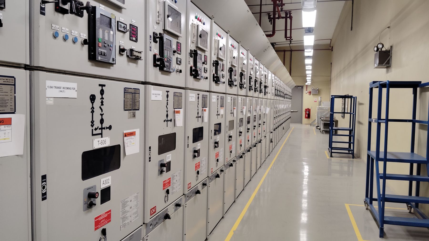
Electrical Panel Monitoring Solution for Local Display, Alarms and RS485 Data
A useful panel monitoring solution connects the electrical system, sensing method, digital meter, local indication, alarm logic and communication system as one verified chain. SENTOP helps panel builders and OEM buyers define what must be measured, how the signal reaches the meter, what operators need to see and which data must be transmitted before an exact model is quoted.
What is an electrical panel monitoring solution?
An electrical panel monitoring solution measures selected electrical quantities and presents them where operators or automation systems can use them. A basic arrangement may provide one local voltage or current display. A connected arrangement can add three-phase values, power and energy calculations, relay alarms, pulse or analog outputs, and RS485 communication to a PLC, gateway, BMS or SCADA platform.
The solution starts with the electrical system, not the meter face. Buyers must confirm AC or DC, single-phase or three-phase wiring, direct input or instrument transformer signals, expected range, auxiliary supply, panel cutout, accuracy purpose, required values, alarm behavior and communication details. The exact model and wiring diagram should be approved together.
Local operational visibility
Give operators a permanent front-panel reading for voltage, current, frequency or another essential value without opening the cabinet.
Feeder and load awareness
Review phase currents, voltage condition, power factor, power or energy trends where the selected meter supports them.
Alarm and control support
Use documented relay or output functions to signal threshold conditions to another circuit; verify logic, ratings and reset behavior.
Connected data collection
Transmit supported values to a control or monitoring system after protocol, serial settings, addressing and register mapping are confirmed.
One measurement must work in the cabinet, on the machine and in operations
Electrical panel monitoring connects three different customer needs: a correctly wired measurement inside the enclosure, a clear status for the person working at the equipment and usable data for the team supervising the wider process.

The reading must support a real maintenance decision
A front-panel value is useful when the operator understands what it represents, where it is measured and what condition requires attention. Clear units, labels, phase mapping and alarm behavior matter as much as the display itself. Photo: mickael ange konan / Pexels.


Follow the signal from the electrical circuit to the operator
Select each stage to see what it contributes and which information must be confirmed. A mismatch at any stage can make a good meter unsuitable for the project.
Define the electrical system first
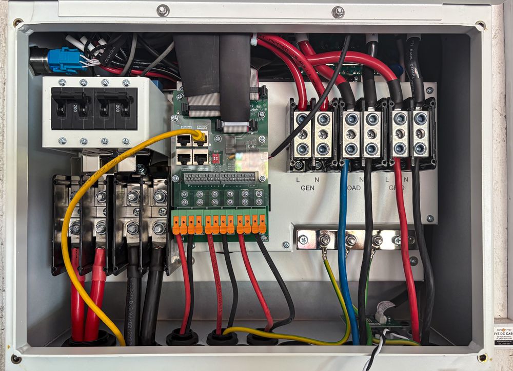
The meter must match the circuit it is connected to. Identify AC or DC, single-phase or three-phase, wiring configuration, nominal and expected operating range, frequency and the point being monitored.
Start with what the customer must see, detect or record
One project may need only a clear local value. Another may need phase comparison, demand awareness, alarms or connected data. Avoid paying for functions that are not used, but do not omit interfaces that the system design requires.
Voltage Condition
Display an AC or DC voltage at a feeder, control supply, battery system or process circuit. Confirm whether the signal is direct or transformer-derived and which line relationship is required.
Prepare: voltage range, AC/DC, wiring points, supply and cutout.Current and Loading
Show direct current, shunt-based DC current or CT-operated AC current. Three-phase current monitoring can help operators compare loading across phases.
Prepare: range, direct/CT/shunt input, ratio, polarity and overload conditions.Multifunction Feeder Data
Combine supported voltage, current, frequency, power factor, power or energy values in one panel position. The exact parameter set varies by model.
Prepare: system wiring, CT/VT ratios, required values and accuracy purpose.Threshold Alarm
Request a documented relay or digital output when a measured condition crosses a defined threshold. Confirm output ratings and downstream circuit requirements separately.
Prepare: alarm variable, setpoint logic, delay, hysteresis, reset and contact duty.RS485 Data Collection
Send supported readings to a PLC, gateway, BMS or SCADA system. RS485 describes the electrical interface; protocol and device mapping still require confirmation.
Prepare: protocol, baud, parity, address plan, register list and network topology.Replacement and Retrofit
Match the electrical input and function before checking front size. Similar displays can use different cutouts, rear depths, terminals, supplies and communication maps.
Prepare: front/rear/label photos, opening dimensions, wiring and old model manual.Build a discussion-ready panel monitoring brief
Choose the system, monitoring objective, input method and data use. The result identifies a solution direction and the information still needed for model confirmation.
Project inputs
This tool narrows the solution architecture. It does not confirm voltage limits, CT burden, accuracy, protection, wiring or the final meter model.
Your solution direction
Three-phase connected monitoringMultifunction meter with CT input and RS485 review
Review a three-phase multifunction panel meter direction. Confirm the wiring system, voltage input, CT ratio, required electrical values and serial communication details as one package.
Planning direction only. Final selection and commissioning must use the exact product manual, wiring diagram, ratings, instrument-transformer data and project requirements. Work on electrical panels must be performed by qualified personnel using appropriate safety procedures.
Match the monitoring layer to the project question
| Monitoring layer | Typical direction | Project data to confirm | Common mistake |
|---|---|---|---|
| Single local value | Digital voltmeter or ammeter with a clear permanent display | AC/DC, range, direct/CT/shunt input, auxiliary supply, cutout and accuracy | Choosing by display digits without confirming the safe electrical input and measurement accuracy. |
| Three-phase current | Three-phase ammeter using the documented CT arrangement | 3P wiring, CT quantity and ratio, current range, overload, phase mapping and display sequence | Ordering from primary current only while omitting CT secondary and meter input data. |
| Feeder monitoring | Multifunction meter for supported voltage, current, frequency, power, power factor or energy values | 3P3W/3P4W, voltage input, CT/VT ratios, required values, accuracy purpose and update needs | Assuming every multifunction model provides the same calculations, demand data or energy functions. |
| DC circuit monitoring | DC voltmeter or ammeter with direct or shunt-compatible input | Polarity, expected range, shunt signal and ratio, supply isolation, display scaling and wiring | Connecting a shunt signal to a meter input that expects direct current or a different signal level. |
| Threshold indication | Meter with documented relay, digital or analog output function | Measured variable, setpoint, delay, hysteresis, fail-state, reset and downstream input or contact duty | Treating a display alarm symbol as an available external relay output. |
| Connected monitoring | Meter with supported RS485 communication and documented application protocol | Protocol, baud, parity, address, register map, data types, scaling, topology, gateway and polling system | Assuming RS485 automatically means Modbus RTU or that register maps are identical across models. |
Duty note: General operational monitoring, power-quality analysis, protective functions and regulated energy settlement are different duties. Confirm the applicable standard and exact model documentation instead of treating one meter category as interchangeable with another.
RS485 is one part of the integration specification
RS485 identifies an electrical interface, not a complete data contract. A usable integration also needs an application protocol, serial settings, device addressing, register definitions, data types, scaling rules and a network design that the system integrator can commission.
Monitoring priorities change with the panel and operating task
Machine Control Panel
Provide a clear control-supply or load indication, support threshold alarms and share selected data with the machine PLC where required.
Confirm: machine supply, measurement point, control voltage, PLC interface and documentation.Low-Voltage Distribution Feeder
Review phase loading and supported power or energy values at incoming or outgoing feeders without confusing operational monitoring with protection or billing.
Confirm: one-line diagram, 3P system, CT/VT data, feeder range and accuracy purpose.Generator and Transfer Panel
Coordinate source-related measurements, frequency, voltage, phase values and communication with the changeover system design.
Confirm: source systems, measurement points, ATS/MTS auxiliaries and required source data.DC Power and Battery Panel
Monitor DC voltage or current using the correct direct or shunt signal, polarity, isolation and display scaling for the application.
Confirm: nominal and maximum DC values, shunt data, polarity, supply and alarm requirement.
Verify the complete measurement path before accepting the readings
Commissioning should compare installation and configuration with the approved drawings, exact meter manual and sensing-device data. Qualified personnel must use suitable procedures and test equipment.
Turn the monitoring requirement into a reviewable model specification
Send the one-line diagram, measurement list or replacement information you already have. SENTOP can help organize the meter direction and missing data before quotation.
Define the monitoring purpose
Separate local indication, alarm, control-system data, operational energy tracking and any regulated metering duty.
Confirm the electrical system
Review AC/DC, wiring configuration, ranges, frequency, measurement points and the one-line diagram.
Match sensing and meter input
Coordinate direct inputs, CT, VT or shunt data with the exact model's documented terminals and scaling.
Specify outputs and communication
Define alarms, relays, pulses, analog outputs or RS485 details rather than using a generic “communication required” note.
Review sample and repeat supply
Verify a representative model in the target panel, then control approved model codes, manuals, labels and packaging for repeat orders.
Continue with the page that matches your next decision
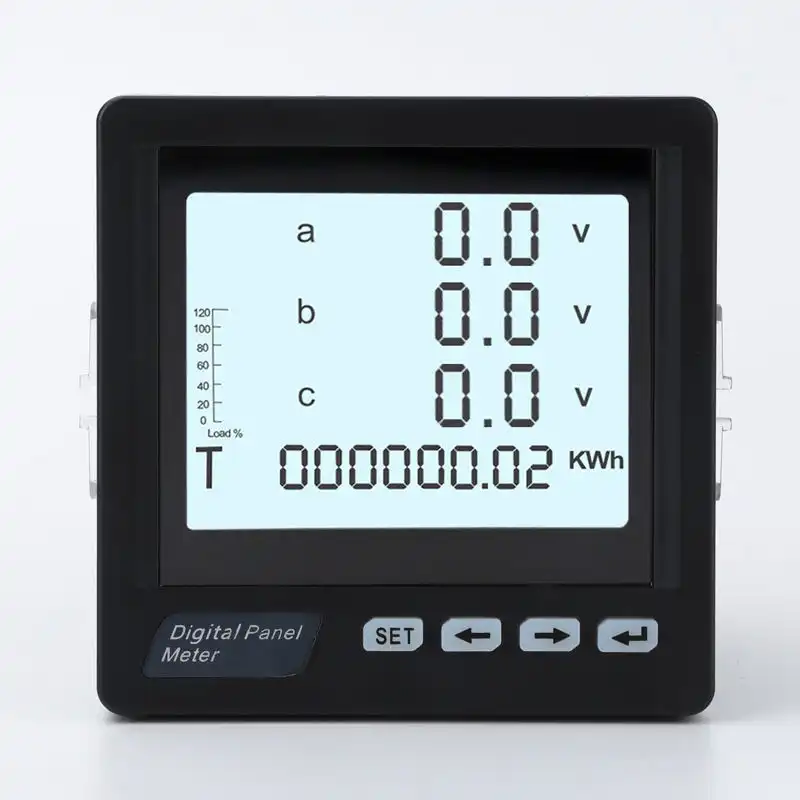
Digital Panel Meter Range
Review SENTOP voltmeter, ammeter, three-phase and connected panel-meter directions by measurement task and input method.
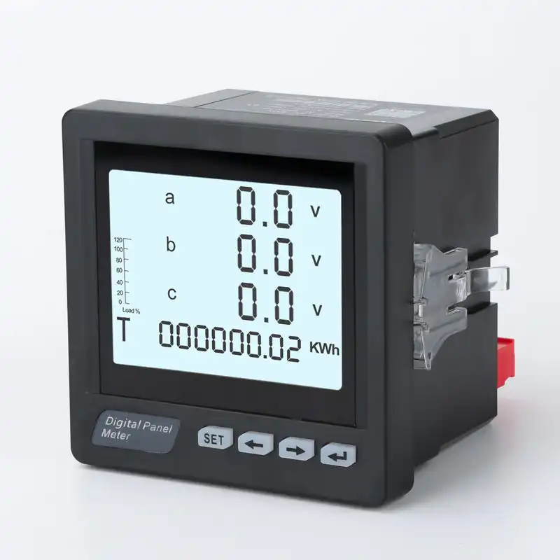
Panel Meter Selection Guide
Work through system type, measurement, input signal, cutout, accuracy, outputs and communication when the model direction is not yet clear.
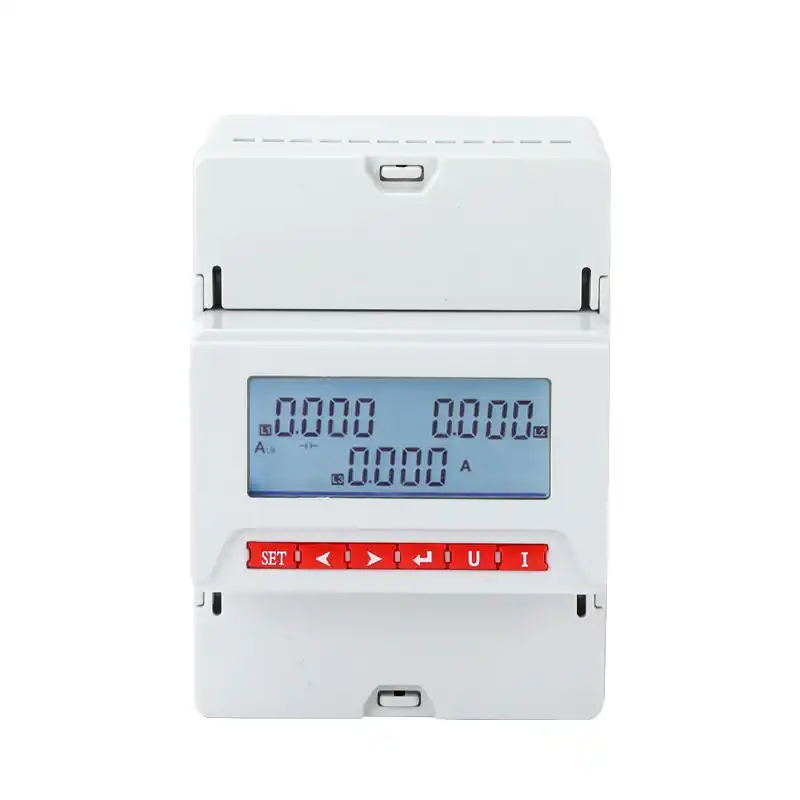
Digital Panel Meter Manufacturer
Review SENTOP's project-matching, sample confirmation, documentation and repeat-supply process for OEM and panel-builder programs.
Send the measurement system, not only the required display size
A complete RFQ allows the electrical input, sensing device, meter function, panel installation and data interface to be reviewed together. Replacement projects should include clear front, rear and label photos.
Use standards and communication documents for the final design
The applicable requirements depend on the monitoring duty, system, market and contract. These official sources provide technical context but do not replace the purchased standards, meter manual or project verification.
Visual sources: industrial control-room, engineering, panel-service and automation photographs are provided by Pexels and credited beside the relevant content. The current-transformer photograph by Loasa is available in the public domain via Wikimedia Commons.
Questions before solution selection
Use these answers to prepare the electrical, installation and communication information for model review.
What is included in an electrical panel monitoring solution?
A solution may include the measurement point, direct or transformer-derived sensing, digital panel meter, auxiliary supply, local display, alarm or relay outputs, RS485 communication, gateway and supervisory software. The required parts depend on what must be measured, displayed, detected and transmitted.
What electrical values can a panel monitoring system measure?
Depending on the exact meter, a system may measure voltage, current, frequency, power factor, active or reactive power, apparent power, energy or DC values. Do not assume every multifunction meter supports every parameter, calculation, demand function or energy register.
When is a current transformer needed for a panel meter?
A CT-operated meter is used when the selected AC current measurement arrangement requires a current-transformer secondary signal rather than direct load current. The CT primary and secondary ratings, accuracy, burden, frequency, installation and meter input must be reviewed together.
Does RS485 mean the panel meter supports Modbus RTU?
No. RS485 defines an electrical communication interface. The device must also document the application protocol, serial settings and register map. Request the current communication manual for the exact meter model before integration.
Can one meter monitor a three-phase electrical system?
Yes, when the exact meter supports the intended three-phase wiring arrangement and measurement functions. Confirm whether the system is 3P3W or 3P4W, the voltage connection, CT arrangement, ratios, phase mapping and required displayed or transmitted values.
How do I choose between local display and connected monitoring?
Choose a local display when operators need an immediate value at the panel. Add connected monitoring when readings must be collected, trended or used by another system. Many projects need both, but protocol, register mapping, network design and commissioning must be included in the scope.
Can a panel monitoring meter be used for billing?
Do not assume so. General operational monitoring and regulated or revenue energy settlement are different duties. Billing may require a specific accuracy class, approval, sealing and installation method. Verify the applicable rules and exact model documentation.
What should be checked during meter commissioning?
Confirm model and wiring, auxiliary supply, system configuration, CT/VT/shunt ratios, polarity, phase mapping, readings under known conditions, alarm outputs, communication settings, register values, scaling and the required documentation.
How do I replace an existing digital panel meter?
Match the electrical function and input first, then verify auxiliary supply, cutout, front dimensions, rear depth, mounting clips, terminal access, outputs and communication. Send front, rear and label photos together with the old wiring diagram or manual where available.
What should I send SENTOP for a monitoring solution review?
Send the one-line diagram, AC/DC and wiring system, measurement points, expected ranges, CT/VT/shunt data, required values, cutout, supply, accuracy purpose, alarms, outputs, communication details, quantity, destination, approvals and replacement photos if applicable.
Send your one-line diagram, required values or existing meter information
SENTOP can help organize the meter direction, sensing input, panel installation, output options and communication data that should be confirmed before quotation.
