
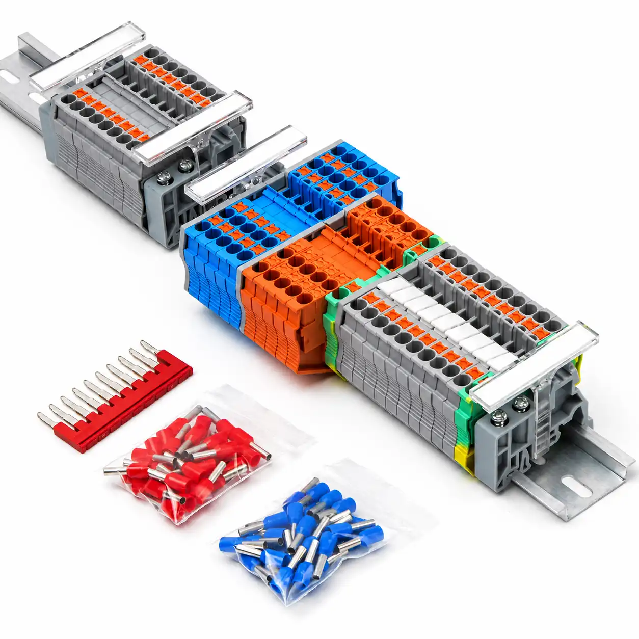
Terminal Block Accessories for a Complete DIN Rail Assembly
Source end clamps, end covers, marker strips, fixed bridges, DIN rails and wiring ducts as one coordinated project BOM. SENTOP reviews the exact terminal series, side profile, bridge pitch, marker format, rail type and cabinet layout before quotation.
Choose accessories from the finished assembly, not appearance alone
Terminal block accessories complete the mechanical fixing, insulation, circuit identification, electrical bridging, mounting and cable-routing functions around a terminal strip. A similar color or shape does not prove compatibility.
Start with the terminal model and circuit plan. Then confirm which sides are open, where groups must be separated, which positions share potential, how every point will be marked, which rail supports the terminal foot and how wires will enter the duct.
Hold the terminal row in position
End clamps retain the completed terminal group on the selected DIN rail.
Close and separate exposed sides
End covers and partition plates complete the intended insulation and grouping structure.
Identify terminals and circuits
Markers connect physical positions to drawings, wire numbers and maintenance records.
Distribute common potential
Compatible bridges connect selected terminal positions according to the circuit design.
Six accessory groups for complete cabinet wiring
Select by function first, then verify the exact mechanical or electrical interface. SENTOP can review existing models, photos, drawings, samples and mixed accessory BOMs.
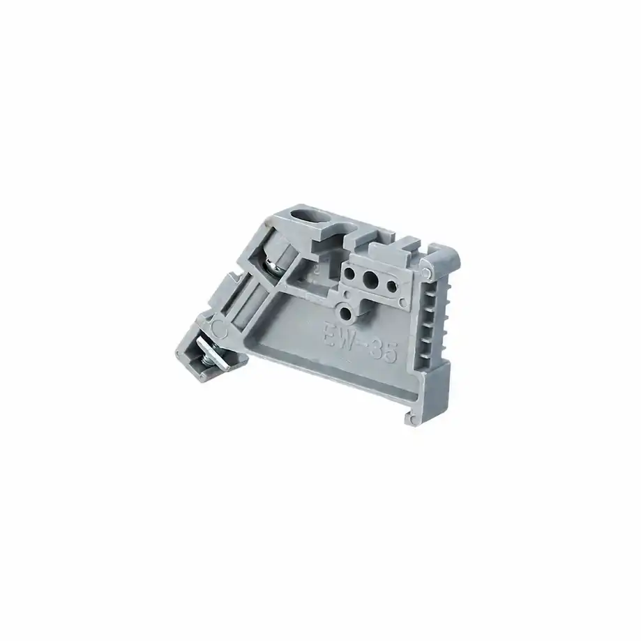
End Clamps
Secure the terminal group at both ends of the rail and help prevent sideways movement during wiring, transport and equipment operation.
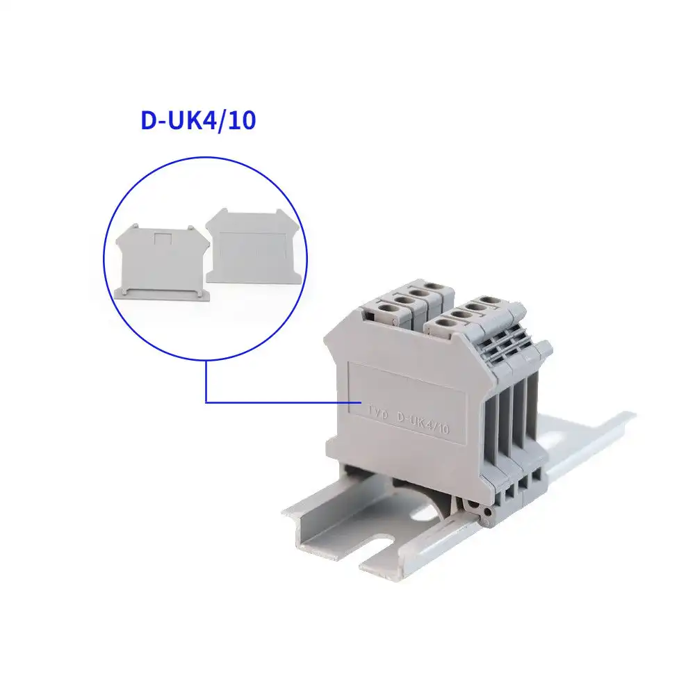
End Covers and Partitions
Close an open terminal side or separate selected circuit groups. The cover contour must match the exact terminal housing profile.
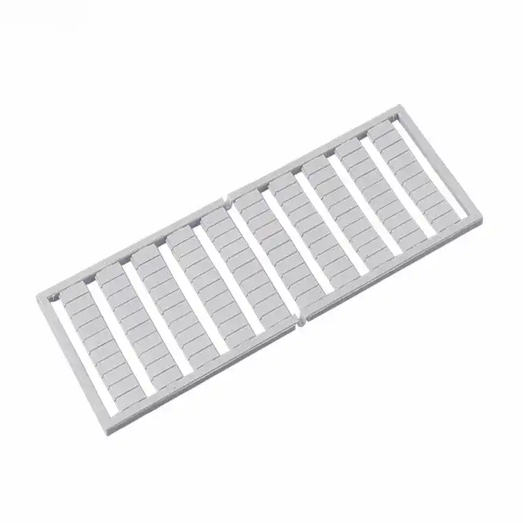
Marker Strips
Identify terminal numbers, circuit functions, cabinet groups and maintenance points in line with the wiring diagram and production rules.
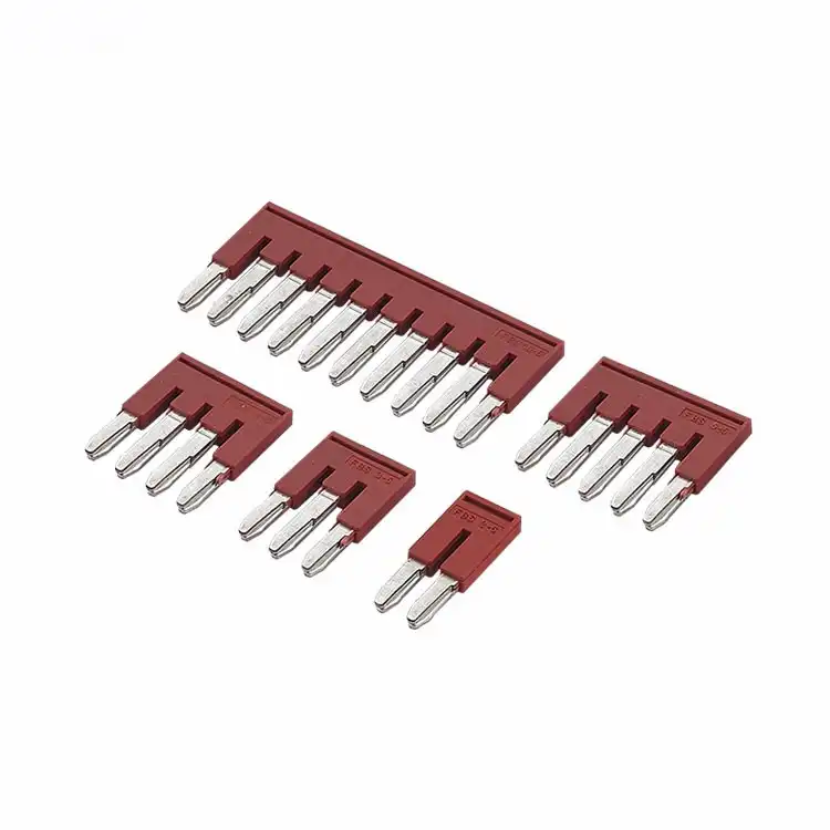
Fixed Bridges and Jumpers
Electrically connect selected terminal positions to distribute a common potential and reduce repeated external jumper wiring.
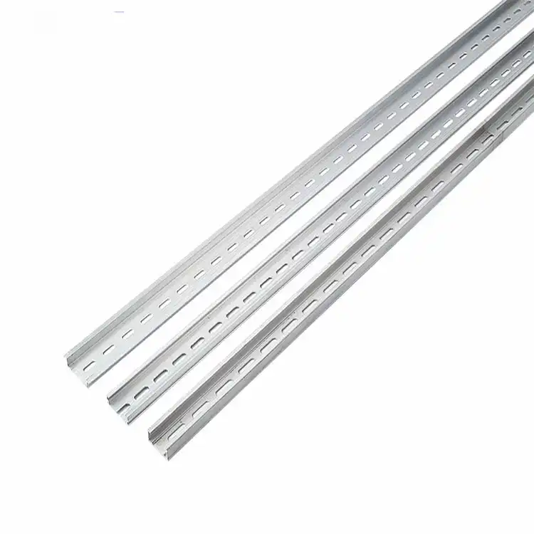
DIN Rails
Provide the mounting foundation for terminal blocks, end clamps and compatible cabinet devices in organized electrical assemblies.
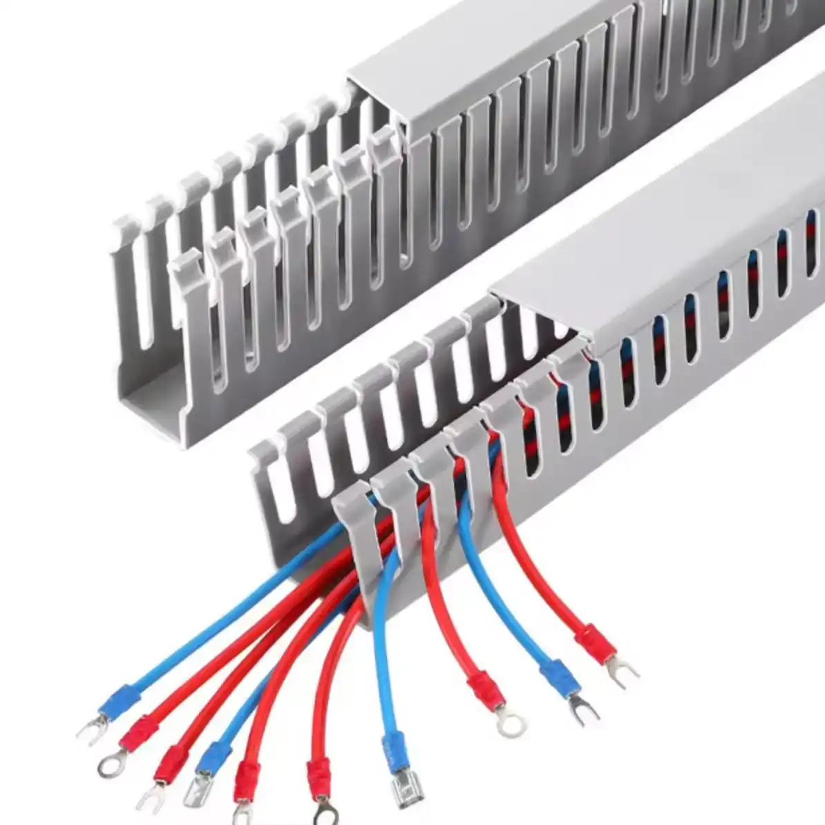
Wiring Ducts
Route and organize conductors between terminal strips and cabinet devices while preserving inspection and maintenance access.

Build the accessory list around the terminal strip drawing
A reliable BOM connects the schematic, terminal schedule and physical cabinet layout. Follow the assembly sequence so no essential side cover, bridge or marker is omitted.
Check the interface that makes each accessory fit
Accessory names are generic; compatibility is model-specific. Compare the exact interface below before approving a replacement or mixed-family BOM.
| Accessory | Primary matching interface | Project data to provide | Common mismatch risk |
|---|---|---|---|
| End clamp | DIN rail profile, clamp foot and available rail space | Rail dimensions, installation direction, clamp type and terminal-row quantity | A clamp may fit one rail profile but not retain another securely. |
| End cover | Terminal side contour, height, width and orientation | Exact terminal model, side photo, left or right position, color and quantity | Similar housings may have different open-side geometry or fixing points. |
| Partition plate | Terminal outline, separation position and required clearance | Terminal sequence, voltage groups, bridge layout, model and plate position | A thin end cover should not be assumed to provide the required separation function. |
| Marker strip | Marker groove, carrier type, pitch and visible marking area | Terminal model, text list, numbering order, color and print format | The marker may be too wide, loose in the groove or unreadable after wiring. |
| Fixed bridge | Bridge channel, contact spacing, pole count and electrical rating | Terminal family, connected positions, circuit diagram, current and quantity | Incorrect pitch or contact geometry can prevent insertion or create an unsafe connection. |
| DIN rail | Terminal mounting foot, rail profile, height and material | Terminal series, rail drawing, length, perforation and surface requirement | Matching only rail width can overlook height, thickness or mounting-foot differences. |
| Wiring duct | Panel space, conductor volume, slot pattern and cover interface | Width, height, length, fill requirement, routing drawing and material requirement | Insufficient duct capacity or finger spacing can obstruct wire routing and maintenance. |
Replacement reminder: Send the complete terminal model, clear front and side photos, rail profile, dimensions and existing accessory photos. Appearance alone is not enough to confirm interchangeability.
Estimate quantities from each rail section and circuit group
These planning rules help identify missing information before quotation. Final quantities still depend on the exact terminal system, panel drawing and approved assembly method.
End clamps
Plan retaining parts at the boundaries of every independent terminal group or rail section according to the selected clamp and panel design.
Start from the number of completed rail sectionsEnd covers and partitions
Count exposed terminal sides and every planned separation point. Mixed models or functions can change the required cover profile.
Start from open sides and group boundariesMarkers
Map terminal numbers and levels to the wiring schedule, including PE, spare, disconnect and multi-level positions that need identification.
Start from the complete marking scheduleBridges and jumpers
Calculate each bridge group from the schematic. Record pole count, skipped positions and any separate potentials within the terminal row.
Start from the electrical connection planDIN rail length
Add terminal widths, covers, partitions, clamps, marker carriers and spare positions, then include installation and cutting allowance.
Start from the physical terminal sequenceWiring duct
Use the cabinet route, conductor quantity, bending space, duct fill target and device clearances to determine duct size and length.
Start from the cabinet layout and wire listAccessory supply organized around the way your team builds
The same accessory range can serve different purchasing and assembly workflows when the BOM, labeling and package groups are prepared for the actual project.
Control panel builders
Complete marked terminal rows for PLC, relay, signal, control-power and protective-earth circuits.
Useful input: terminal schedule and cabinet drawingMachine manufacturers
Repeat approved terminal and accessory kits across machine models, production batches or assembly stations.
Useful input: machine BOM and customer item codesDistribution equipment
Organize potential distribution, separation, identification and mounting components for electrical enclosures.
Useful input: circuit grouping and current requirementsMaintenance and retrofit
Match an installed end cover, clamp, bridge, marker or rail from model data, dimensions, photos and samples.
Useful input: front, side and installation photosDistributors and stockists
Build accessory coverage around the terminal families and sizes most frequently supplied to local customers.
Useful input: sales history and core terminal rangeSend enough detail for a compatible quotation
Provide the available information even if the accessory model is unknown. A terminal BOM, photos and assembly drawing can often identify missing details faster than a short product name.
Identify the system
Terminal series, exact models, rail profile, accessory type, photos, dimensions and existing part numbers.
Define the layout
Terminal sequence, open sides, bridge positions, marker text, duct size, rail length and cabinet groups.
Confirm the order
Quantity by item, destination country, documentation, sample need, customer labels and packaging method.
Keep the accessory list aligned with the approved terminal BOM
Mixed accessory orders depend on product identity, quantity and package separation. SENTOP can organize parts by model, terminal strip, cabinet, machine, production batch or customer code.
Continue building the complete connection system
Terminal block accessory questions
Use these answers to prepare a clearer BOM and reduce compatibility revisions.
What accessories are needed for a complete terminal block assembly?
A typical DIN rail terminal assembly can require terminal blocks, end clamps, end covers, partition plates, markers, bridges or jumpers, DIN rail and wiring duct. The exact list depends on the terminal family, circuit functions, grouping, rail layout and cabinet design.
Are terminal block accessories interchangeable between different series?
Not automatically. End-cover contours, bridge pitch, marker grooves, terminal width, mounting feet and rail profiles can differ between product families. Confirm the exact terminal model and accessory interface before substitution.
What is the difference between an end clamp and an end cover?
An end clamp mechanically retains a terminal group on the DIN rail. An end cover closes an open terminal side and completes the intended insulation structure. They perform different functions and may both be required in one assembly.
How do I choose a fixed bridge or jumper?
Confirm the terminal family, bridge channel, pitch, number of connected positions, adjacent or skipped poles, installation direction and electrical requirement. The bridge layout should follow the circuit schematic.
How do I calculate the required DIN rail length?
Add the widths of all terminal positions, end covers, partitions, end clamps, marker carriers and planned spare positions. Then include installation and cutting allowance according to the cabinet layout.
Can SENTOP provide printed terminal markers?
Marker supply can be reviewed from the exact terminal model, marker format, required text or numbering sequence, color, quantity and project grouping. Confirm the final printed content before production.
What information is needed to select wiring duct?
Provide the required duct width, height and length, conductor quantity, routing drawing, slot format, cover requirement, material, color, flame-retardant requirement and available cabinet space.
Can accessories be packed by cabinet or terminal strip?
Yes. Mixed terminals and accessories can be organized by terminal strip, cabinet, machine, project BOM, customer item code or production batch when the grouping and labels are confirmed before packing.
What should I send for replacement accessory matching?
Send the complete terminal model, accessory model if available, clear front and side photos, dimensions, rail profile, terminal quantity, circuit function and required order quantity. A physical sample or drawing can improve the review.
Send one accessory model or a complete terminal-strip BOM
SENTOP can review end clamps, end covers, partitions, markers, bridges, DIN rails, wiring ducts and related terminals for replacement, panel building, OEM production and repeat supply.
