
Cold Press Terminal Guide
Select and Verify Cold Press Terminals for Reliable Crimp Connections
Match the conductor, terminal barrel, connection shape, insulation system and crimp tooling as one approved combination. This guide helps buyers, panel builders and wiring teams define a practical cold press terminal requirement before model selection and production release.
Answer First
How do you choose a cold press terminal?
Start with the actual conductor, then choose the connection interface and environmental protection. Select a terminal barrel that explicitly accepts the conductor construction and size, and use the terminal manufacturer's specified crimp tool, die and application dimensions.
The terminal, wire and tooling form one crimp system. A correct-looking terminal can still produce an unreliable joint when the strand construction, insulation diameter, die geometry, strip length or tool setting is wrong.
Define the conductor
Copper or other permitted material, mm² or AWG, strand count, plating, insulation type and outside diameter.
Define the connection
Stud, screw, tab, mating connector, inline splice or terminal-block entry with exact dimensions.
Define the environment
Temperature, vibration, moisture, chemicals, corrosion exposure, enclosure and service procedure.
Release the crimp process
Terminal code, wire code, strip length, tooling, crimp dimensions, inspection and test requirements.
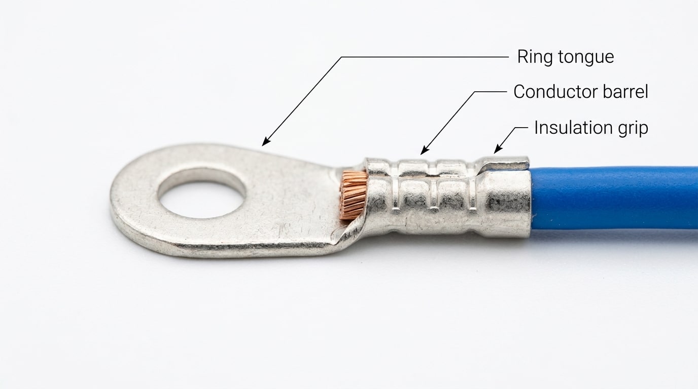
Terminal Anatomy
Read the terminal as three working zones
The exact construction varies by terminal family. Identify which part carries current, which part supports the insulation and which part mates with the equipment before choosing the product and tooling.
Interactive Selection Starting Point
Build a practical cold press terminal direction
Choose five project conditions. The result creates a starting direction and adds the summary to the enquiry popup. It does not replace the exact product and crimp application specification.
Cold Press Terminal Types
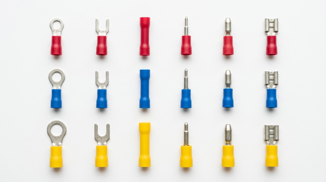
Choose the contact shape from the equipment interface
Wire size determines the barrel direction; the equipment connection determines the tongue or mating shape. Both must be correct.
Ring Terminals
A closed ring surrounds the stud and remains captured until the nut or screw is removed. Use where retention is more important than rapid disconnection.
Fork and Spade Terminals
An open tongue can be installed without fully removing the screw. Use only where the connection design permits an open fork and provides suitable retention.

Blade and Quick-Disconnect Terminals
Male tabs and female receptacles create a serviceable push-on connection. Treat tab width, thickness, retention and mating cycles as a defined connector interface.
Butt Splices and Parallel Splices
Join conductors without a stud or tab. Each wire entry, conductor combination, sealing method and support requirement must be included in the splice specification.
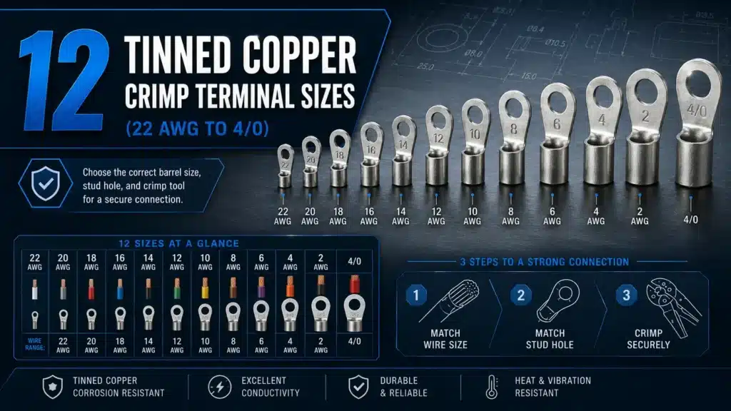
Pin Terminals and Wire-End Ferrules
Provide a controlled end for compatible screw-clamp or spring connections. Pin terminals and ferrules are different product systems and must be accepted by the receiving terminal.

Tubular Cable Lugs
Larger conductors commonly use tube-style lugs and dedicated mechanical, hydraulic or powered tooling. Treat them as a separate product and process range from small pre-insulated terminals.
Wire and Barrel Compatibility
Nominal size is only the first wire check
Two wires marked with the same mm² or AWG can have different strand counts, conductor diameters, plating and insulation outside diameters. The terminal and tool must accept the actual wire.
Controlled Crimping Process
Quality is produced by the complete application setup
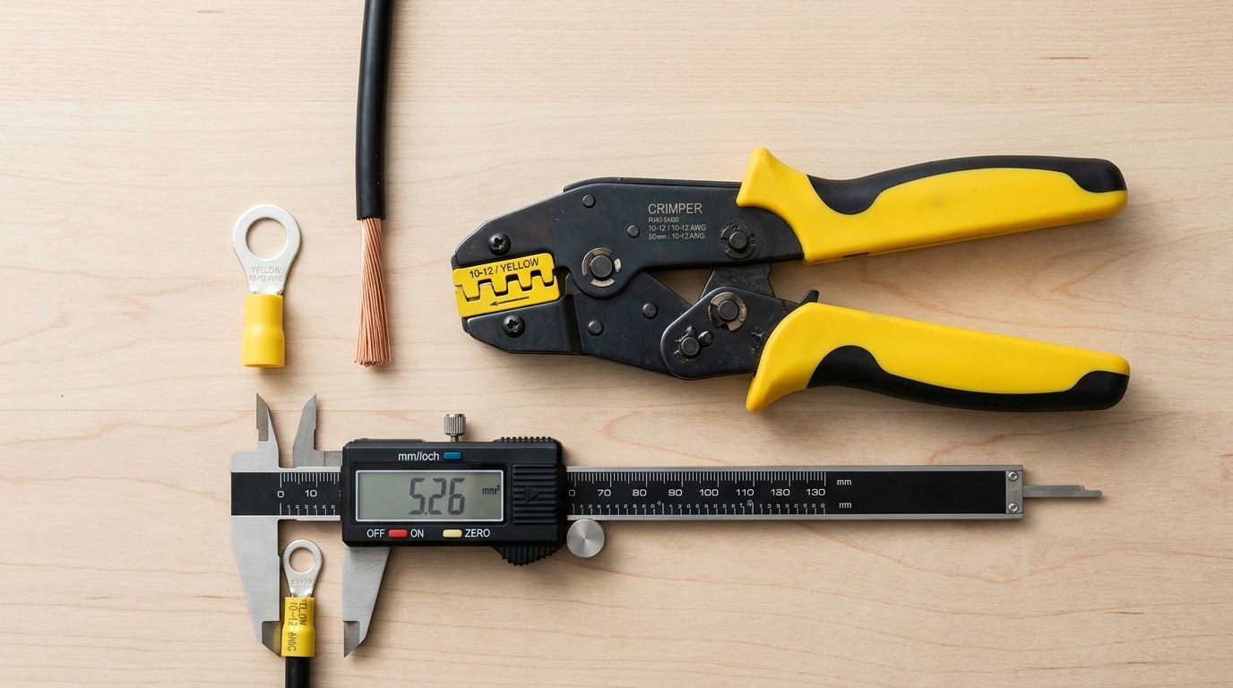
Use the terminal manufacturer's application specification and approved tooling. The steps below organize the process but do not replace model-specific instructions.
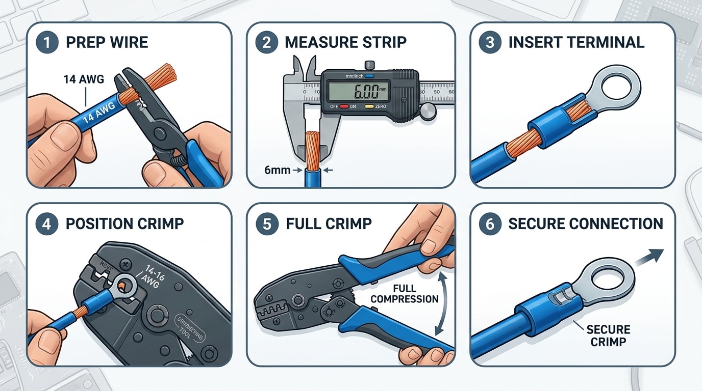
Verify materials
Confirm terminal code, wire code, lot, condition, approved tool, die, applicator and current setup record.
Prepare the wire
Strip to the specified length without nicking, cutting, losing or contaminating conductor strands.
Position the terminal
Orient the barrel, seam, tongue and insulation support in the correct die location.
Insert completely
Place all strands in the conductor barrel and position the insulation at the specified support zone.
Complete the cycle
Operate the controlled-cycle tool or press fully; do not correct a poor crimp by squeezing the same joint again.
Inspect and verify
Check appearance and dimensions, then perform the required mechanical or electrical verification plan.
Crimp Acceptance
Release the connection with measurable evidence
A reliable control plan separates setup approval, routine inspection and periodic verification. Use limits from the exact terminal and application specification rather than a universal force or crimp-height table.
Correct terminal and wire
Verify item codes, conductor specification, insulation diameter, lot and approved substitutions before setup.
Crimp height and width
Measure at the defined location with the specified method and compare with released limits for the terminal-wire-tool combination.
Strands and barrel fill
Confirm all strands are captured, conductor position is correct and there are no cut, folded or escaped strands.
Jacket restraint
Check the support crimp where applicable for correct position and restraint without damaging the insulation.
Pull-force verification
Use the applicable terminal, wire and project specification for sample preparation, test speed, minimum force and failure interpretation.
Resistance and temperature
Where required, validate voltage drop, resistance stability, temperature rise or environmental performance under the defined test program.
Construction Comparison
Select insulation and barrel style from the installation environment
Temperature values, materials and approvals vary by product. Use this table to define the direction, then confirm the exact model data.
| Terminal direction | Useful starting point | Confirm before release |
|---|---|---|
| Pre-insulated terminal | Indoor equipment and control wiring where the insulation support and wire range suit the application. | Insulation material, temperature range, flame requirement, wire OD, barrel range, die and color system. |
| Non-insulated terminal | Compact assemblies or applications using a separate boot, sleeve or enclosure protection. | Touch protection, spacing, post-crimp insulation, conductor support, plating and installation environment. |
| Sealed or heat-shrink terminal | Harnesses exposed to moisture, splash or contaminants when the complete sealing process is approved. | Seal material, recovery process, adhesive, cable OD, temperature, chemical exposure and finished inspection. |
| Open-barrel contact | Connector housings and harness production using a dedicated contact, applicator and insertion process. | Contact cavity, conductor and insulation crimp, crimp height, bellmouth, cutoff tab, insertion and retention. |
| Tubular cable lug | Larger power conductors connected to a bolted bus, device or battery terminal. | Conductor class, barrel, palm, stud, die code, number and sequence of compressions, standard and sealing. |
Avoid Crimp Failures
Most failures start with a mismatched process input
Use these checks during tool setup, first-article approval and routine production audits.
Standards and Practical Evidence
Use current standards with the exact application specification
The applicable standard depends on the terminal type, conductor range, equipment and destination. These references organize the review; they do not replace model certification or the equipment designer's requirements.
IEC 60352-2:2024
The current IEC publication covers general requirements, test methods and practical guidance for applicable solderless crimped connections, including defined uninsulated or pre-insulated barrels and wire ranges within its scope.
View the IEC publication →Molex Quality Crimp Handbook
This industry handbook explains why terminal, wire and tooling are the three key elements of a crimp process and discusses setup, measurement, pull testing and common defect recognition.
Open the handbook →Terminal Application Data
Keep the approved terminal code, conductor code, strip length, tooling, die or applicator, crimp dimensions, test limits and inspection method together. The released combination is more important than any generic chart.
Prepare a Useful Enquiry
Send three groups of data for faster terminal matching
A wire datasheet, device drawing and existing terminal sample can prevent several rounds of model and tooling questions.
Wire and electrical duty
Conductor material, mm² or AWG, strand construction, plating, insulation type and OD, circuit current, voltage and temperature.
Connection and environment
Ring, fork, tab, splice, pin or lug; stud or tab dimensions; mating device; vibration, moisture, chemicals and enclosure.
Production and supply
Hand tool or press, production volume, inspection and test documents, quantity, destination, packaging, labels and schedule.
Cold Press Terminal FAQ
Buyer and crimp-process questions
These answers define a selection direction. Final approval requires the exact terminal, wire, tooling and project specification.
What is a cold press terminal?
Cold press terminal is a common commercial term for a crimp terminal attached to a prepared conductor by mechanical compression without soldering. The exact product may be a ring, fork, blade, receptacle, splice, pin, ferrule or cable lug.
How do I choose the correct terminal size?
Use the actual conductor material, cross-section or AWG, strand construction and insulation outside diameter. Confirm that all values fall within the exact terminal and tooling application data.
Can I select a pre-insulated terminal by color?
Color can help identify sizes within a defined product family, but it is not a universal sizing standard. Always verify the printed model and stated conductor range.
What is the difference between a ring and fork terminal?
A ring fully surrounds the stud and normally requires hardware removal for disconnection. A fork has an open tongue for easier service but must be permitted by the connection design and retention requirements.
Can solid wire be crimped?
Only when the exact terminal, tooling and applicable specification allow that solid conductor. Many common crimp terminals are designed for particular stranded-wire constructions.
Can two wires be crimped in one terminal?
Only use a two-wire crimp when the terminal application data explicitly permits both conductor sizes, constructions and combined insulation dimensions. Do not improvise a double-wire connection.
Should I twist strands before crimping?
Follow the wire and terminal preparation specification. Avoid uncontrolled twisting that changes conductor diameter, strand lay or barrel fill, and do not lose or cut strands.
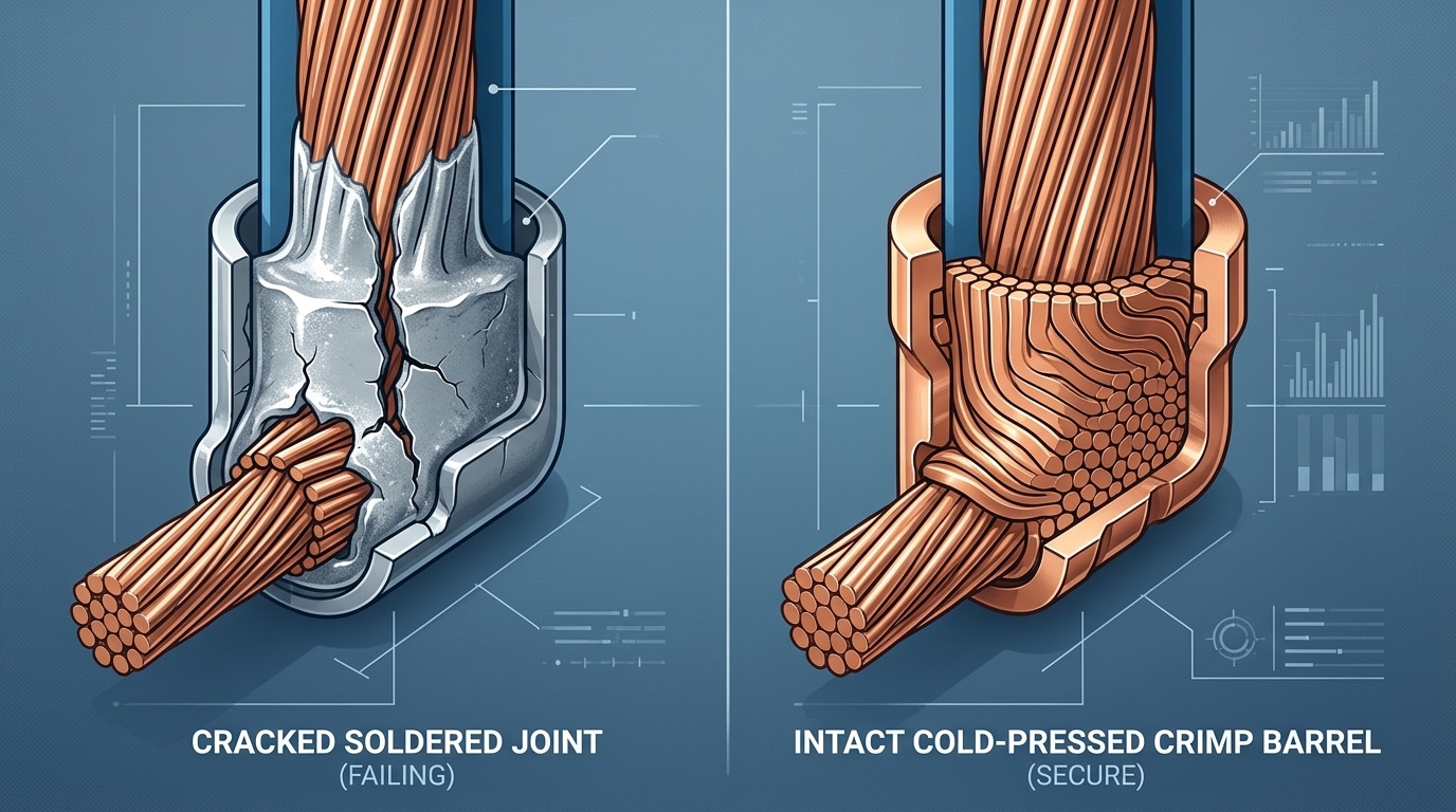
Can I solder a cold press terminal after crimping?
Do not add solder unless an approved process explicitly requires and validates it. A terminal designed as a solderless crimp should be produced and inspected according to its specified crimp process.
Can a crimp terminal be reused?
A terminal that has already been crimped should normally be treated as a single-use part. Remove the rejected termination and remake it with a new terminal according to the repair procedure.
How can I tell whether a crimp is good?
Check terminal and wire identity, strand capture, conductor and insulation position, barrel condition and the specified crimp dimensions. Apply the required pull-force or electrical verification plan; appearance alone is not enough.
What information is needed to replace an existing terminal?
Send all markings, front and side photos, conductor data, stud or tab dimensions, insulation OD, crimp shape, mating device and a physical sample where possible.
Can SENTOP supply terminals with matching crimp tools?
SENTOP can review the requested terminal, conductor range, tooling direction, production quantity, samples and document requirements. Exact tool availability and compatibility must be confirmed for the selected terminal series.
Continue Your Research
Move from the guide to the relevant selection path
Cold Press Terminal Support
Send the wire data, connection dimensions and production requirement
SENTOP supports cold press terminal selection, replacement review, samples, tooling discussion, OEM requirements and bulk supply for panel builders, equipment manufacturers, harness producers, distributors and project buyers.
