

Organize building power distribution around loads, continuity and maintenance
SENTOP supports buyers, panel builders and electrical equipment suppliers with terminal blocks, transfer switches, digital panel meters and selected low-voltage products for commercial buildings, public facilities and infrastructure distribution projects.
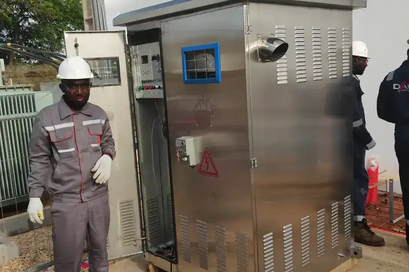
Define the operating conditions before comparing component models
Buildings combine utility supply, distribution boards, mechanical services, life-safety interfaces, tenant loads, standby power and monitoring. A useful component review starts by identifying the circuit function and the conditions that the complete assembly must handle.
Supply architecture and earthing
Confirm source voltage, frequency, phases, neutral treatment, earthing arrangement and available standby source.
Fault current and protection coordination
Use the project study to define breaking capacity, protective characteristics, selectivity and upstream or downstream coordination.
Installation and enclosure conditions
Review indoor or outdoor use, ambient temperature, ingress risk, ventilation, mounting space, cable entry and access.
Operation, identification and maintenance
Plan isolation, labeling, metering visibility, spare capacity, replacement access and terminal-strip organization.
Follow power from the incoming source to the final connected circuit
Each stage has a different electrical duty. Use the one-line diagram and circuit schedule to keep component selection aligned across the complete distribution path.
Utility or Site Supply
Incoming voltage, phases, earthing, available fault current and source authority requirements.
Confirm source data and responsibility boundary.Main Distribution
Main isolation, circuit protection, bus arrangement, metering and assembly ratings.
Coordinate incomer and assembly data.Standby Changeover
Automatic or manual transfer between normal and generator or alternative supplies.
Define essential loads and transfer sequence.Area and Service Boards
Distribution to floors, mechanical services, tenant zones, lighting and equipment.
Review diversity, spare ways and enclosure use.Load Protection
Branch protection and residual-current protection according to load and installation needs.
Match poles, current, curve and fault duty.Metering & Interfaces
Panel meters, control power, contactors and organized terminal connections.
Confirm signals, communication and wiring plan.Different buildings create different electrical priorities
Building type is a starting point, not a final specification. Select the closest environment, then confirm the actual loads, supply arrangement and project documents.
Offices, retail, hotels and commercial complexes
Commercial projects commonly combine landlord distribution, tenant circuits, mechanical services, public areas, metering and selected standby loads.
Apartments, towers and mixed-use developments
Residential and mixed-use projects require clear separation between common services, dwelling or tenant circuits, commercial areas and shared standby functions.
Schools, healthcare support areas and civic facilities
Public facilities may include essential services, controlled access, mechanical plant, monitored distribution and operational procedures that require disciplined documentation.
Water, transport, communications and site services
Infrastructure environments often combine distributed enclosures, pumps or motors, remote monitoring, harsh conditions and a defined operating or maintenance procedure.
Keep the three core SENTOP ranges visible inside the broader panel BOM
The product family should follow the circuit function. Exact models remain subject to the project ratings, drawings, dimensions and applicable documentation.
Transfer Switches for Source Changeover
Automatic or manual changeover directions for normal and standby supplies. Confirm poles, current, utilization duty, transfer sequence, controller, interlocking and installation arrangement.
Explore Transfer SwitchesDigital Panel Meters for Electrical Visibility
Panel-mounted voltage, current, energy or multifunction measurement. Confirm measured quantities, direct or transformer input, auxiliary supply, panel cutout, accuracy and communication.
Explore Digital Panel MetersTerminal Blocks for Organized Panel Wiring
DIN rail and related terminal directions for power, control, signal and protective-earth wiring. Confirm conductor size, connection method, rail, circuit function, markers, bridges and accessories.
Explore Terminal BlocksMatch each product group to the same project data
This matrix helps purchasers and panel builders organize a comparable enquiry. It does not replace the project design or coordination study.
| Project item | What to confirm | Product decisions affected | Useful document |
|---|---|---|---|
| Source system | AC voltage, frequency, phases, neutral, earthing and standby source | Breaker poles and voltage, transfer arrangement, meter input and control supply | One-line diagram |
| Load and diversity | Connected load, demand, inrush, load type, duty and priority | Rated current, trip characteristic, contactor duty, transfer-switch capacity and conductor range | Load schedule |
| Fault and protection | Prospective fault current, protection study, selectivity and backup requirements | Breaking capacity, coordination, protective device family and assembly rating | Short-circuit and coordination study |
| Standby continuity | Essential loads, source sequence, transfer time, interlocking and monitoring | Automatic or manual transfer method, poles, controller and auxiliary interfaces | Changeover sequence |
| Metering and BMS | Measured values, CT or direct input, protocol, addresses, outputs and panel cutout | Meter type, accessories, auxiliary supply and communication configuration | Metering points list |
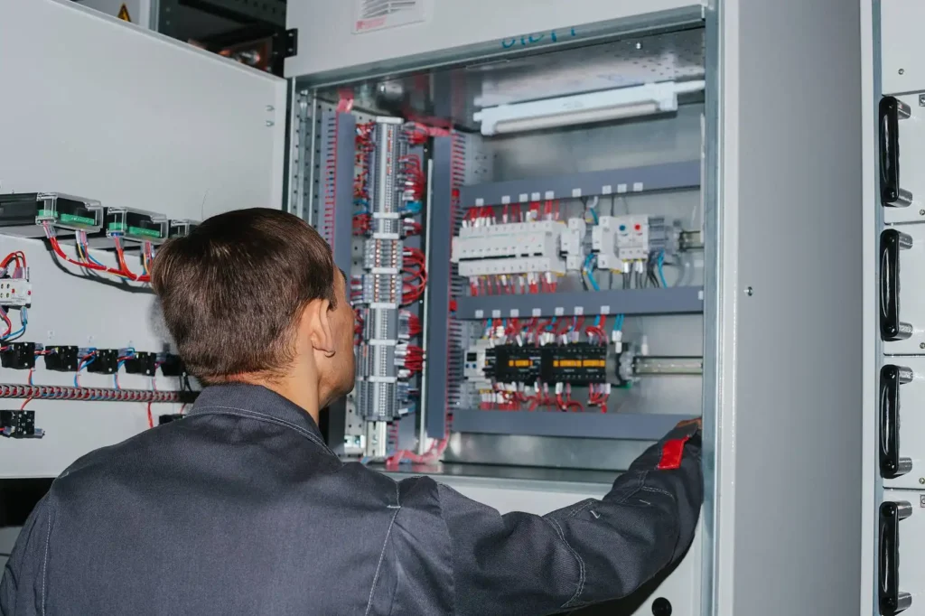
| Panel construction | Enclosure, ambient conditions, layout, cable entry, rail, terminals, labels and spare space | Physical dimensions, mounting, terminal family, accessories and packaging by panel | GA and wiring drawing |
| Market and documents | Destination, applicable standards, required certificates, labels and language | Eligible model, marking, document scope and approval review | Project specification |
Important: specify which party owns the electrical design, assembly verification, installation, testing and authority approval. A component quotation should not silently assume those responsibilities.
Organize the commercial order around the approved technical scope
SENTOP can review a single product request or selected product groups within a wider panel BOM. The level of support depends on the information available and the agreed supply responsibility.
Component compliance and installation compliance are not the same decision
Building electrical installations and low-voltage assemblies are evaluated as systems. The project team should identify the applicable rules, authority requirements, design responsibility and verification plan before finalizing individual devices.
Addresses fundamental principles, assessment of general characteristics and safety requirements for low-voltage electrical installations.
View the official IEC publicationCovers general definitions, service conditions, construction requirements, technical characteristics and verification requirements for assemblies.
View the official IEC publicationDefines specific requirements for power switchgear and controlgear assemblies within its stated voltage and application scope.
View the official IEC publicationProvides common rules and requirements for relevant low-voltage switchgear and controlgear product standards.
View the official IEC publicationSend the documents that define the distribution system
You can begin with a one-line diagram, panel schedule, BOM, model list or clear photos of an existing assembly. Unknown items can be identified for clarification instead of guessed.
Questions before requesting electrical components
Use these answers to prepare a clearer discussion with SENTOP and your responsible electrical project team.
What information should I send for a building electrical component quotation?
Send the available one-line diagram, panel schedule, load data, system voltage, phases, fault level, product functions, quantities, destination and required documents. A BOM or clear nameplate photos can also be used as a starting point.
Can SENTOP select all protection ratings from the building type alone?
No. Building type does not determine the exact current, poles, breaking capacity, trip characteristic or coordination. Those values must come from the project design, load calculation and fault or protection study.
When does a building project need an automatic transfer switch?
An ATS may be considered when selected loads must transfer automatically between normal and standby sources. The project team must define the essential loads, source arrangement, transfer sequence, poles, current, utilization duty, interlocking and monitoring requirements.
How should digital panel meters be specified for building distribution?
Confirm measured quantities, AC or DC system, direct or CT input, nominal range, auxiliary supply, panel cutout, display, accuracy, communication protocol and required outputs. Coordinate the meter and transformer or sensor as one measurement system.
Why include terminal blocks in the panel BOM instead of buying them separately?
A complete terminal-strip review keeps conductor sizes, connection method, PE positions, markers, bridges, end plates and rail accessories compatible. It also improves wiring identification and repeat-order consistency.
Can component certificates prove that the complete distribution board complies?
No. Component data supports selection, but the complete assembly and installation have separate design, construction, verification and approval responsibilities. Confirm the applicable standards and authority requirements for the target market.
Can SENTOP support replacement products for an existing building panel?
SENTOP can review the existing model, nameplate, front and side photos, dimensions, wiring, ratings and required accessories. A replacement should not be chosen from appearance alone; compatibility and project responsibility must be confirmed.
Can several product categories be combined in one project enquiry?
Yes. You can submit terminal blocks, transfer switches, digital panel meters and selected protection, control or distribution products within one enquiry. Separate each panel or system area and include quantities so the proposed scope remains clear.
Have a one-line diagram, panel schedule or existing model list?
Send the available system data, product requirements, quantities, destination and document needs. SENTOP will help organize the next component-matching step.
