
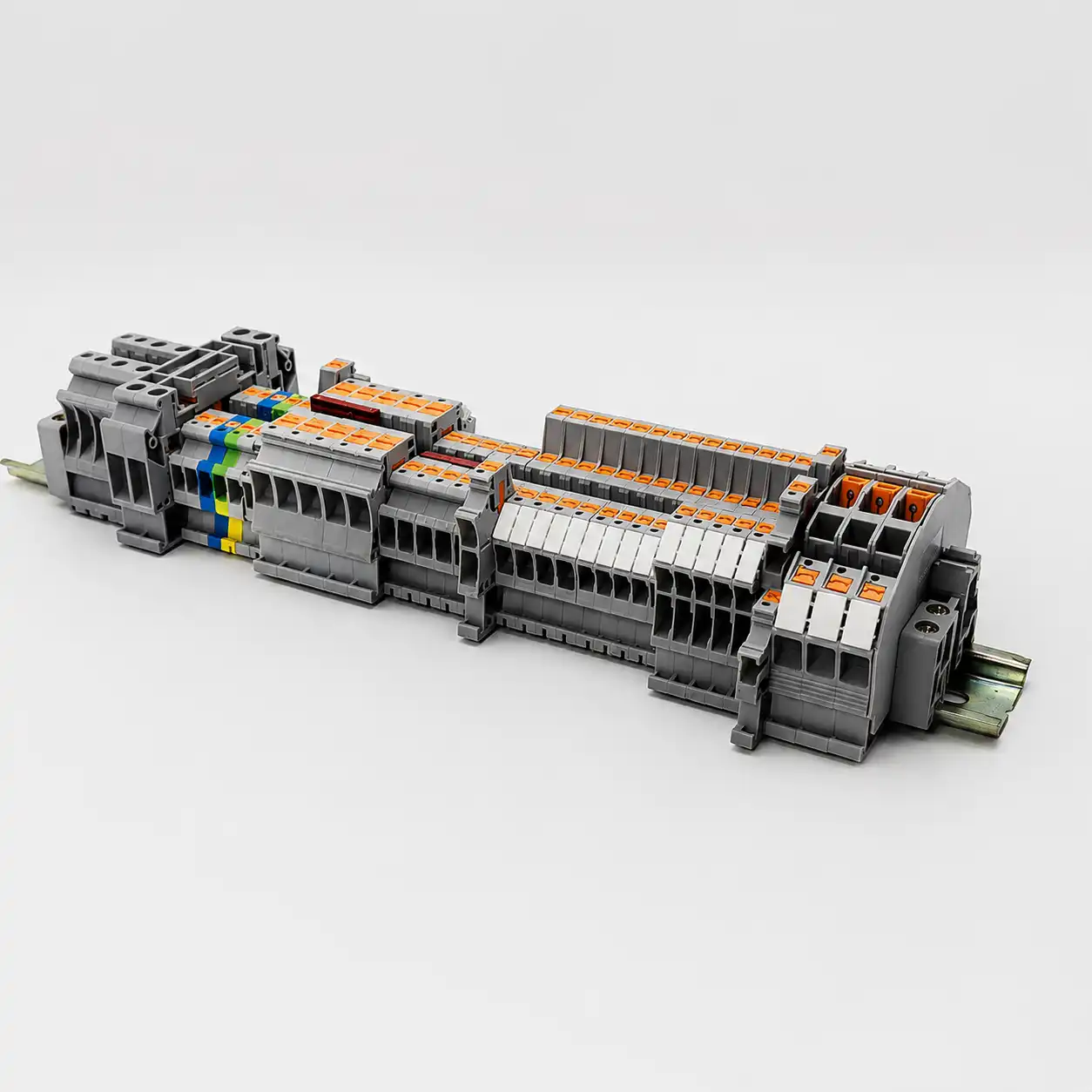
DIN Rail Terminal Blocks for Organized Panel Wiring
Build clear terminal strips for control, signal, protective earth and distribution circuits. SENTOP supplies PTV, PTFIX, PT and ST terminal blocks with model matching, compatible accessories, mixed BOM organization and bulk-order support.
What is a DIN rail terminal block?
A DIN rail terminal block is a modular connector that mounts on a compatible metal rail inside control panels, distribution cabinets, machinery and automation equipment. It creates accessible connection points between field conductors and internal electrical components without requiring every external wire to terminate directly on a device.
A terminal strip is normally built from several functions and accessories. Feed-through positions connect conductors, protective earth terminals handle PE circuits, distribution products create repeated connection points, and compact or multi-level structures help manage limited rail space.
Define the circuit function
Separate feed-through, PE, distribution, signal, power and service requirements before counting terminal positions.
Match the conductor and rating
Confirm conductor construction, cross-section, current, voltage and the electrical requirements for each circuit group.
Choose connection technology
Select vertical wiring, push-in, spring or another model direction according to assembly and service needs.
Complete the terminal strip
Add the correct rail, end parts, bridges, markers, separators and spare positions to the finished BOM.
Choose the series by wiring purpose
PTV, PTFIX, PT and ST solve different panel-wiring requirements. Use the summaries below to identify a starting direction, then confirm the exact model and technical data.
Vertical Wiring Terminal Blocks
PTV terminals provide a vertical conductor-entry direction for compact cabinet layouts and visible front access. Different functions can be arranged into a structured terminal group for field and internal panel wiring.
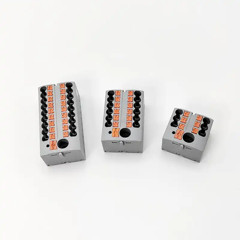
Potential Distribution Blocks
PTFIX products organize one incoming potential into multiple outgoing connection points. They can reduce repeated external branching for control voltage, sensor supply and selected power-distribution tasks.
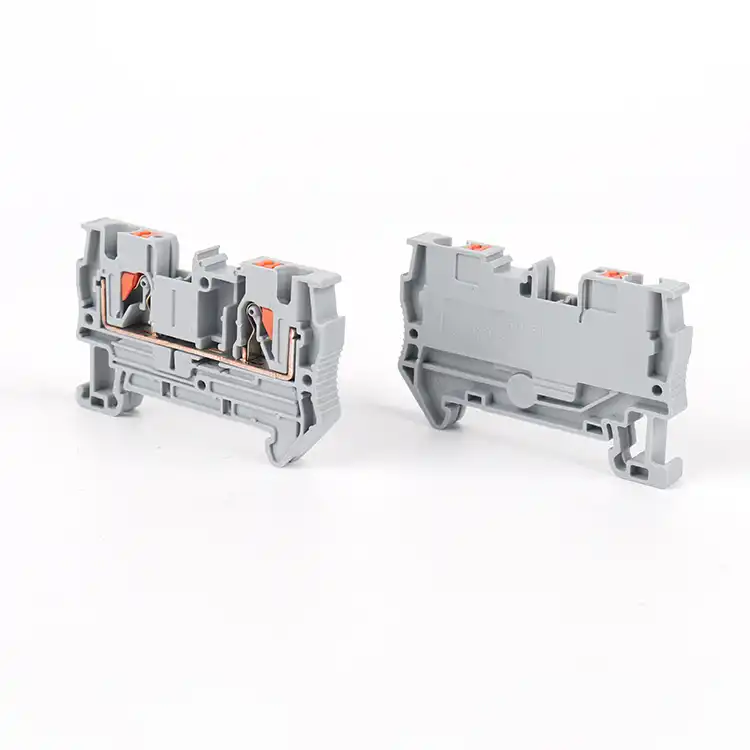
Push-In Terminal Blocks
PT terminals use push-in connection technology for efficient panel assembly when the selected conductor and preparation method support direct insertion. Release and test access depend on the exact model.
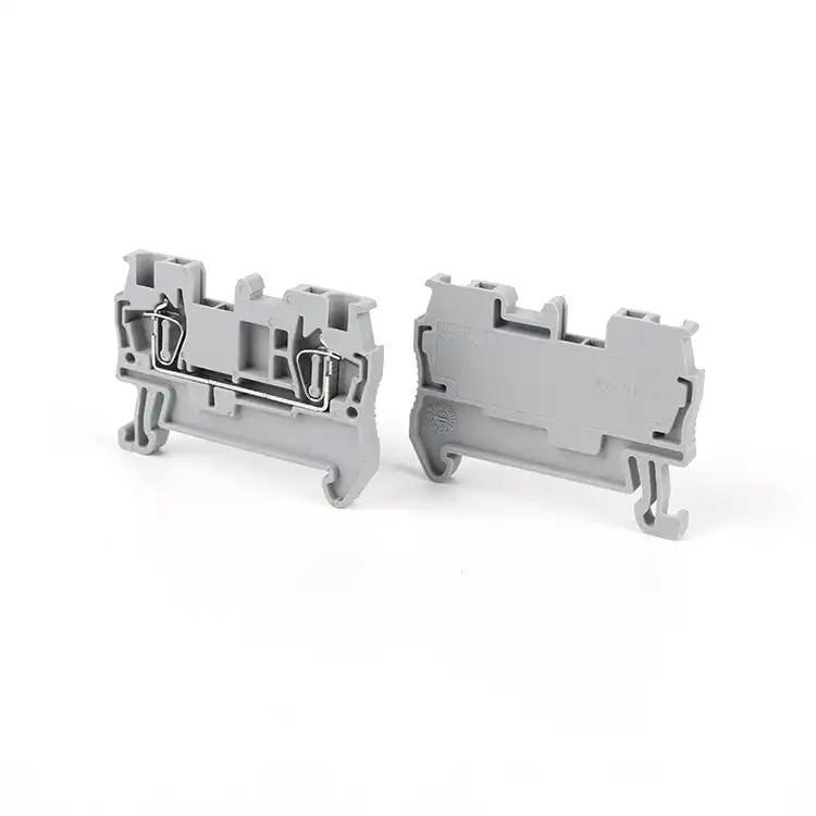
Spring Connection Terminal Blocks
ST terminals use a spring connection structure for industrial cabinet and machinery wiring. The operating method, supported conductors and functional variants should be confirmed for each selected model.
Build each rail section around the wiring problem
A cabinet often uses more than one terminal function. Separate the requirements first, then choose compatible models and accessories for each group.
Feed-Through Connection
Connect an incoming conductor to an outgoing conductor for field wiring, device wiring and normal control circuits.
Confirm wire range, rating and connection technologyProtective Earth
Use dedicated PE terminal models designed for the protective conductor and compatible grounded rail system.
Confirm PE function, rail and conductor rangePotential Distribution
Distribute a common potential from one feed-in point to multiple outgoing circuits with an organized connection plan.
Confirm feed-in, outputs, current and groupingCompact or Multi-Level Wiring
Increase connection density when DIN rail length is limited, while preserving wiring and marking access.
Confirm total height, levels and maintenance clearancePower and Larger Conductors
Select model-specific power terminals or distribution products for higher current and larger conductor requirements.
Confirm exact rating, cross-section and heat conditionsSignal and Sensor Wiring
Group PLC I/O, sensors, actuators and control voltage in clearly marked terminal sections for commissioning and service.
Confirm circuit count, potential groups and labelsPlan the finished terminal strip before ordering individual blocks.
Terminal width alone is not the final rail requirement. End clamps, end covers, separators, bridge access, spare positions and wiring clearances also consume space.
Confirm the rail profile
Check the DIN rail size, material, mounting direction and the terminal foot specified for every selected model. Similar-looking rails are not automatically interchangeable.
Count terminals by circuit group
Separate control, signal, PE, power and distribution positions, then add required spare positions according to the project design.
Add end and separation parts
Include end plates, end clamps and separators required by the exact terminal side profile and circuit layout.
Plan bridges and test access
Reserve access for jumpers, bridges, test points and operating tools without blocking adjacent devices or wiring ducts.
Check conductor routing
Review bend radius, wire entry direction, cabinet depth, duct position and installer hand clearance around the finished rail.
Prepare the marking schedule
Match terminal numbers, PE positions, circuit references and customer codes to the schematic and cabinet documentation.
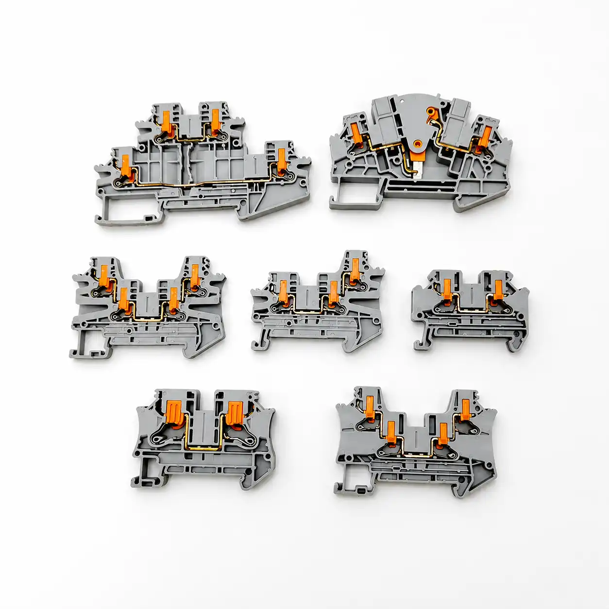
Order an installable terminal group, not loose models
SENTOP can review a terminal schedule, cabinet drawing or mixed BOM and organize the required items by rail, cabinet, machine or project package.
Prepare the data needed for accurate model matching
A useful RFQ connects electrical requirements, cabinet layout and accessory needs. Provide the available information even when the model number is unknown.
| Selection item | Information to provide | Why it matters | Helpful evidence |
|---|---|---|---|
| Circuit function | Feed-through, PE, distribution, signal, power, isolation or other function | Determines the terminal structure and required accessories | Schematic or terminal schedule |
| Conductor | Solid or stranded wire, cross-section, ferrule and insulation diameter | Defines the acceptable connection range and preparation method | Cable or conductor datasheet |
| Electrical requirement | Operating current, voltage, circuit type and applicable standard | Guides model-specific rating and insulation checks | Equipment specification |
| Connection technology | PTV vertical, PT push-in, ST spring or other approved method | Changes assembly, release, tool and service procedures | Work instruction or approved reference |
| DIN rail and space | Rail profile, available length, cabinet depth, duct position and clearance | Ensures the complete strip fits the physical panel layout | Panel drawing or dimensioned photo |
| Terminal arrangement | Quantity by function, PE positions, distribution groups and spare terminals | Defines the rail sequence and mixed-model BOM | Numbered terminal plan |
| Accessories | End covers, end clamps, separators, bridges, markers, rail and test items | Prevents incomplete or incompatible terminal-strip supply | Accessory list or assembly photo |
| Commercial data | Quantity, sample need, packaging groups, destination and documents | Supports accurate quotation, labeling and delivery planning | RFQ sheet or purchase specification |
Replacement reminder: Send the complete model number, front and side photos, dimensions, DIN rail profile, conductor data and accessory list. Similar housing shape or color is not enough to confirm interchangeability.
Compare wiring process before choosing the series
Connection method affects conductor preparation, assembly sequence, tool use and maintenance. Ratings and supported conductors remain model-specific.
| Decision factor | PTV vertical wiring | PT push-in | ST spring connection |
|---|---|---|---|
| Main selection reason | Front-oriented conductor entry and compact cabinet routing | Efficient repeated wiring for compatible prepared conductors | Spring-clamp process for industrial panel wiring |
| Conductor preparation | Depends on the exact PTV connection structure and model | Direct insertion depends on conductor stiffness or ferrule preparation | Depends on conductor construction and model operating method |
| Panel planning focus | Terminal height, depth, visible entry and front access | Insertion and release access for production or service | Operating-tool access and wire-release procedure |
| Best starting point | Compact panels and organized vertical routing | Repeated machine and control-cabinet assembly | Specified spring-clamp control or equipment wiring |
| Final verification | Conductor range, current, voltage, terminal function, rail, dimensions, approvals and accessory compatibility for the exact model | ||
PTFIX is selected primarily by its distribution function, feed-in requirement and number of outgoing connection points rather than by the three-way connection-method comparison above.
Configure the terminal strip from the equipment wiring task
One application may combine several terminal functions. Use the circuit schedule and panel layout to define the final series mix.
Control panels and PLC cabinets
Organize PLC I/O, relay, contactor, sensor, actuator, PE and control-power connections in marked terminal groups.
Typical direction: PTV, PT, ST and PE positions by circuitAutomation equipment
Support repeated machine wiring and structured field connections for sensors, solenoids, switches and control modules.
Typical direction: PT or ST with distribution groupsDistribution cabinets
Arrange incoming, outgoing and repeated potential connections for control voltage and selected branch circuits.
Typical direction: PTFIX and model-specific power terminalsCompact electrical cabinets
Improve conductor routing and connection density where rail length, cabinet depth or front access is limited.
Typical direction: PTV or compact multi-level modelsIndustrial machinery
Create maintainable connection points between internal components, motors, switches, sensors and external cables.
Typical direction: mixed functional terminal stripOEM batch production
Repeat approved terminal sequences, labels and accessory sets across multiple cabinets, machines or production batches.
Typical direction: controlled BOM and grouped packagingFrom a wiring plan to a confirmed DIN rail terminal block BOM
Send the available data even if the model list is incomplete. SENTOP can review the circuit functions, identify missing accessories and organize the quotation by rail, cabinet, machine or project.
Share the wiring data
Send the circuit plan, conductor details, electrical requirements, rail, dimensions and quantities.
Review the terminal system
Confirm models, PE positions, distribution groups, end parts, bridges, markers and spare positions.
Approve sample or quotation
Check the selected BOM, documents, samples, labeling, packaging and delivery plan before bulk ordering.
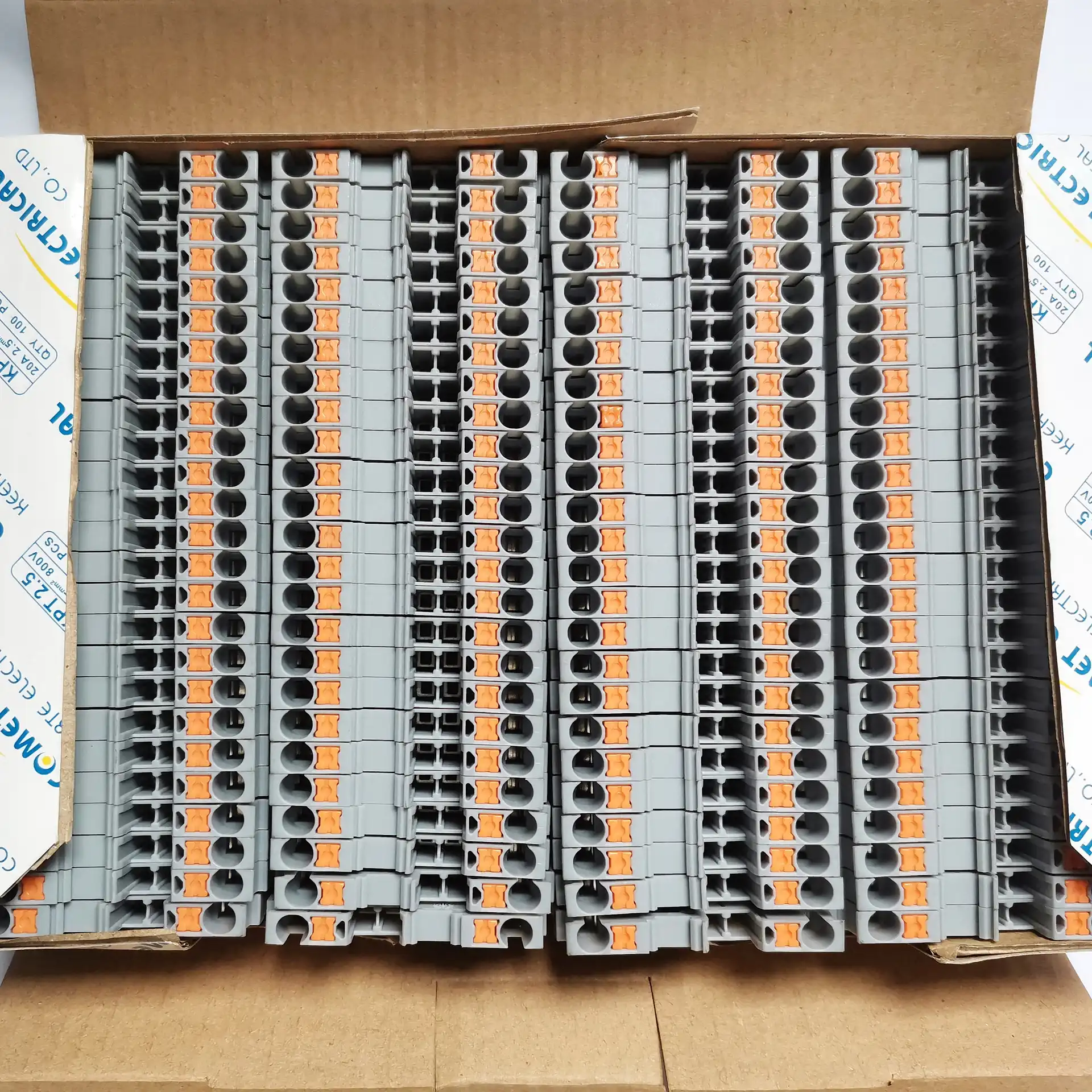
Keep every model and accessory aligned with the approved BOM
Mixed terminal projects depend on correct product identity as much as quantity. Model, function, dimensions, accessories, labels and packaging groups should remain traceable through order preparation.
DIN rail terminal block questions
Initial answers for engineers, panel builders, equipment manufacturers, distributors and project buyers.
How do I choose a DIN rail terminal block?
Start with the circuit function, conductor type and cross-section, current, voltage, connection technology, rail profile and available panel space. Then confirm terminal quantity, PE positions, distribution groups, accessories, approvals, labeling and packaging for the exact models.
What is the difference between PTV, PTFIX, PT and ST terminal blocks?
PTV is a vertical-wiring product direction, PTFIX is used for potential distribution, PT uses push-in connection technology, and ST uses a spring connection structure. Model-level functions, conductor ranges and ratings must still be confirmed.
Do all DIN rail terminal blocks fit the same rail?
No. DIN rails and terminal mounting feet are available in different profiles and dimensions. Confirm the rail specification, terminal foot, installation direction and required end clamp for every selected model.
Can different terminal block series be installed on one DIN rail?
A mixed rail can contain several functions when the products are compatible with the selected rail and the panel design. Review terminal heights, side profiles, end parts, circuit separation, marking and tool access before combining series.
Can a feed-through terminal be used as a PE ground terminal?
No. Protective earth circuits should use a dedicated PE terminal designed to connect the protective conductor through the intended grounding structure and compatible DIN rail system.
How should I calculate the required DIN rail length?
Add the widths of all terminal positions, end covers, end clamps, separators and required accessory space. Include planned spare positions and installation clearance according to the cabinet design rather than using terminal count alone.
Are markers, bridges and end covers interchangeable?
Not automatically. Pitch, side profile, bridge channel, marker carrier and end-cover shape can differ between product families. Match every accessory to the exact terminal series and model.
What should I send for a replacement review?
Send the complete model number, front and side photos, dimensions, rail profile, conductor data, electrical requirement, terminal function, accessories, color and required quantity. A drawing or physical sample can improve the review.
Can SENTOP supply a complete mixed terminal strip BOM?
Yes. SENTOP can review PTV, PTFIX, PT, ST and other required terminal functions together with PE positions, end parts, markers, bridges, DIN rail, labels, mixed quantities and grouped packaging.
Send your wiring plan, model list, photo or BOM for terminal-strip review.
Request PTV, PTFIX, PT or ST models, compatible accessories, replacement matching, complete rail BOM organization or grouped supply for control panels and industrial equipment.
