
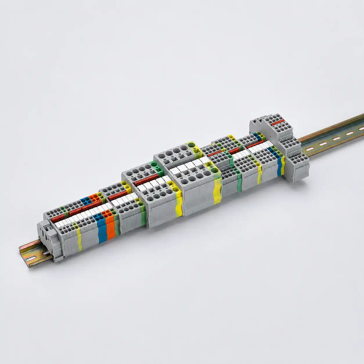
Buyer and Engineering Guide
Terminal Block Selection Guide for Safe, Serviceable Panel Wiring
Use this terminal block selection guide to compare connection technology, conductor type and cross-section, electrical ratings, terminal function, mounting, dimensions, bridges, markers and project approvals. The goal is not only to find a terminal that accepts the wire, but to build a complete terminal strip that can be assembled, tested and maintained.
Selection Answer
How do you select the right terminal block?
Start with the actual conductor and circuit, then choose the connection method and terminal function. Verify the exact model's rated conductor range, current, voltage, strip length, rail profile and accessory system before approving it.
Do not select from current or wire size alone. Two terminal blocks with similar headline ratings may differ in conductor type, clamping method, width, bridge channel, test access, insulation profile and approval scope.
Define the conductor
State copper conductor type, metric or AWG size, insulation diameter, ferrule, strip length and how many conductors enter each clamping point.
Define the electrical circuit
Confirm operating current and voltage, fault conditions, insulation requirements and any PE, fuse, disconnect, measurement or signal function.
Choose connection technology
Compare screw, spring-cage, push-in and other systems against wiring speed, vibration, tool access, conductor preparation and maintenance procedure.
Choose the terminal structure
Select feed-through, multi-level, PE, disconnect, test, fuse, sensor/actuator, distribution, PCB or another functional arrangement.
Complete the terminal strip
Check DIN rail, end clamps, end plates, partitions, bridges, markers, test plugs, wiring duct, clearance and spare positions.
Verify the exact model
Use the manufacturer's drawing, data sheet, approvals and installation instructions for the exact model and destination market.
Interactive Selection Starting Point
Build a practical terminal-block direction
Choose four project conditions. The result creates a useful starting direction and adds the summary to the enquiry popup. Final selection still requires the exact electrical and mechanical data.
Connection Technology Comparison
Choose the clamping method from the wiring process
Connection technology affects conductor preparation, tools, assembly time, vibration behavior, inspection and maintenance. Always check the exact model rather than assuming every product in one technology works identically.
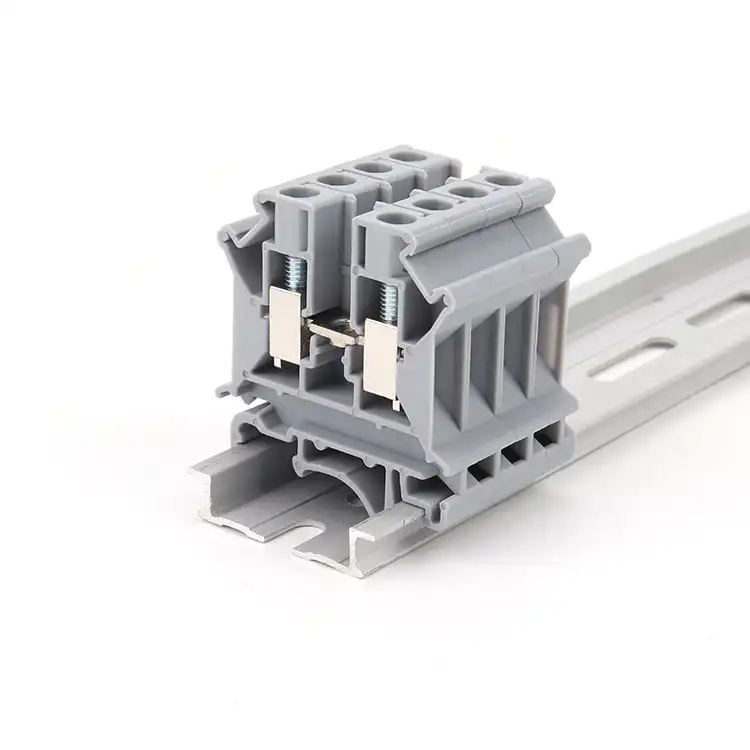
Screw-Clamp Terminal Blocks
A practical choice when installers use controlled tightening procedures and need broad familiarity in industrial or field wiring. Selection must include the specified tightening torque, conductor preparation and inspection process.
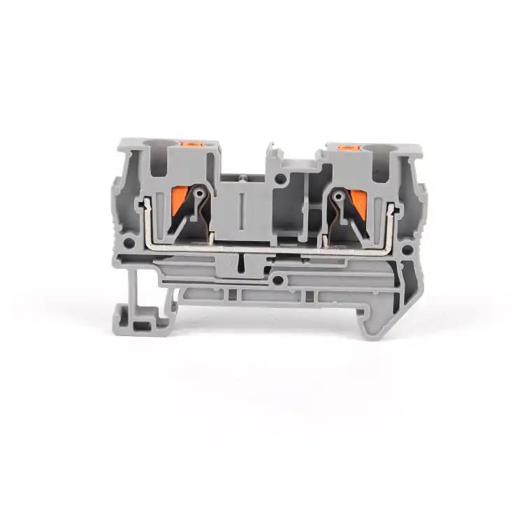
Spring-Cage Terminal Blocks
The spring is opened with the specified tool before conductor insertion. Spring pressure can suit vibration-sensitive equipment and mixed conductor workflows when the model's conductor data and actuation method are followed.
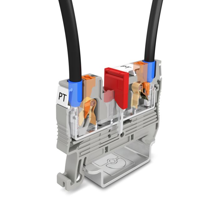
Push-In Terminal Blocks
Compatible solid conductors and fine-stranded conductors with suitable ferrules can often be inserted directly. Other conductor types may require push-button or tool actuation. The exact insertion rules are model-specific.
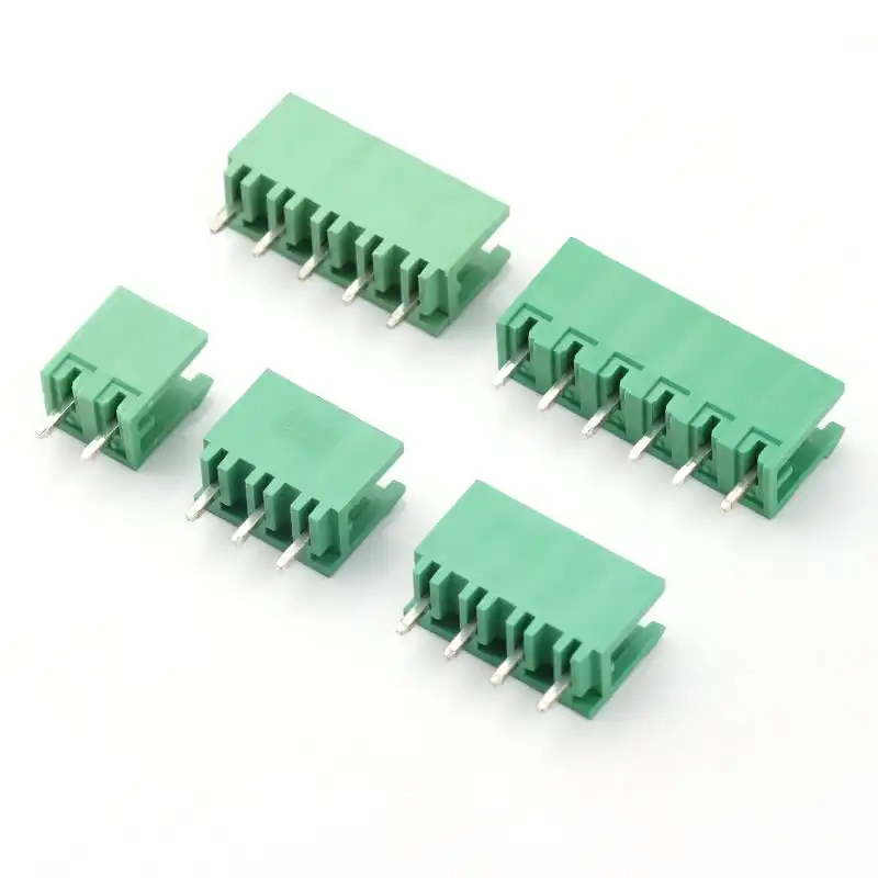
Plug-In and PCB Terminal Blocks
Use when field wiring must connect to a PCB, or when a prewired plug should detach from equipment. Plug, header, pitch, coding, orientation and PCB footprint must be treated as one mating system.
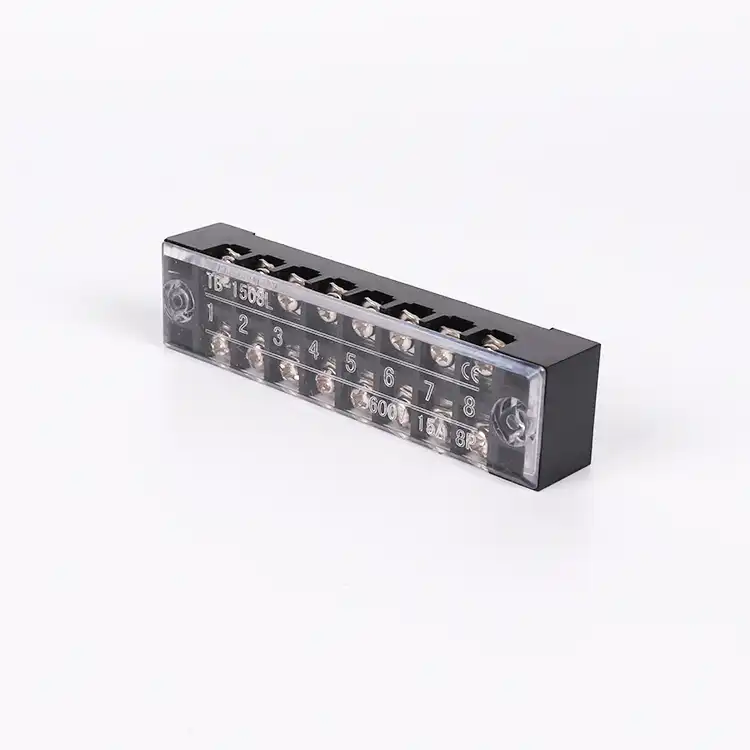
Barrier and Fixed Terminal Strips
Separated poles and direct mounting can suit power supplies, appliances, equipment and compact distribution points. Select the strip as a complete mechanical item, not as independent terminal positions.
Conductor Compatibility
The wire must match the clamping unit
Conductor cross-section is only one part of the check. Construction, preparation, insulation, ferrule and insertion method can change what the terminal accepts.
Electrical and Mechanical Verification
Read the data sheet as a complete rating system
The printed current and voltage are not universal permissions. Compare ratings under the applicable standard, conductor data, neighboring terminals, bridges, ambient conditions and installation instructions.
| Selection item | What to verify | Why it matters |
|---|---|---|
| Rated cross-section | Nominal size plus minimum and maximum ranges for each conductor construction | Solid, stranded, flexible and ferruled conductors may have different permitted ranges. |
| Rated current | Exact model, conductor size, bridge configuration, ambient and adjacent loading | Current capability depends on contact and thermal conditions, not opening size alone. |
| Rated voltage | Applicable standard, pollution degree, overvoltage category, creepage, clearance and installation | The same physical terminal may carry different declared values under different approval systems. |
| Impulse withstand | Declared Uimp and the insulation coordination required by the equipment | Transient withstand must fit the electrical environment and insulation design. |
| Short-time withstand | Terminal, PE path, bridge and conductor behavior for the applicable fault duty | A normal load-current rating does not describe short-circuit performance. |
| Voltage drop | Verified contact performance and correct installation | Poor preparation, loose screws or damaged conductors can create heat and instability. |
| Dimensions | Terminal width, height, depth, end plate, partition, tool and wire-bend space | Rail-length calculations that ignore accessories and access often fail during assembly. |
| Approvals | Certificate owner, exact model, conductor range, standard edition and target market | A family name or similar appearance does not prove that a model is within certificate scope. |
Terminal Block Functions
Choose the function before choosing the series code
A terminal strip usually combines several functions. Organize the circuit first, then match each position and its accessories.
Feed-Through Terminal Blocks
Connect field and internal conductors point to point. Confirm number of connections, conductor range, width, bridge channels and markers.
PE Ground Terminal Blocks
Connect protective conductors to the supporting rail through an approved PE path. Verify the rail, foot, conductor and short-time current data.
Double- and Multi-Level Terminals
Increase circuit density for control, signal or sensor wiring. Check level assignment, total height, visibility, bridges and tool access.
Disconnect and Test Terminals
Create an intentional point for isolation, testing or measurement. Define normal state, operating sequence, test plugs and safety procedure.
Fuse and Component Terminals
Combine connection with a fuse, diode, resistor or indicator function. Verify component size, circuit protection, heat and replacement access.
Distribution Terminal Blocks
Divide one incoming potential among several outgoing conductors. Confirm feed-in and output sizes, current path, bridge or bus arrangement and covers.

DIN Rail and Accessory System
Approve a complete strip, not loose terminal blocks
A correct terminal block can still create an unusable assembly when the rail, end cover, bridge, marker or spacing is wrong. Build and approve the BOM as one coordinated system.
Avoid Selection Failures
Problems usually begin before the first wire is inserted
Use these checks during model review, drawing approval and first-article assembly.
Standards and Evidence
Verify the standard against the terminal function
The applicable edition and certification scope depend on the exact product and destination. These standards organize the review; they do not replace model certificates, local rules or the equipment designer's responsibilities.
IEC 60947-7-1:2025
Requirements for terminal blocks and specified test-disconnect terminal blocks with screw-type or screwless clamping units for copper conductors.
View the IEC publication →IEC 60947-7-2
Requirements for PE and specified PEN protective conductor terminal blocks that connect copper conductors to the fixing support.
View the IEC publication →IEC 60947-7-3
Safety requirements for fuse terminal blocks. Confirm the valid edition, fuse system, thermal behavior and exact model scope.
View the current IEC 60947 series →IEC 60715
Dimensional requirements for mounting rails used for switchgear, controlgear and accessories. Match the terminal foot to the rail profile.
UL / CSA model scope
Check the exact certificate, use group, conductor data, field- or factory-wiring conditions and any required spacings for the target market.
Application-specific requirements
The final terminal strip must also satisfy the equipment, panel, wiring, grounding, identification and installation requirements that apply to the project.
Prepare a Useful Enquiry
Send three groups of data for faster terminal-block matching
A wiring diagram, terminal schedule, existing model photo or sample can shorten the review. SENTOP can then identify missing model, accessory and documentation details.
Electrical and functional data
Voltage, current, circuit type, PE or functional requirements, short-time current, test or disconnect needs and target market.
Wire and preparation data
Solid, stranded or flexible copper, metric/AWG size, ferrule, insulation diameter, number of conductors and stripping requirements.
Mechanical and commercial data
DIN rail, terminal count, colors, bridges, markers, end plates, samples, quantity, packaging, certificates and delivery destination.
Terminal Block Selection FAQ
Buyer and engineering questions
These answers help define a selection direction. Use the exact model data sheet and project rules for final approval.
How do I choose the correct terminal block size?
Match conductor construction and cross-section first, then verify current, voltage, terminal function, width, rail, accessories and installation space. The nominal cross-section is not the complete conductor range.
Should I choose screw, spring-cage or push-in terminal blocks?
Choose from the wiring process. Screw terminals suit familiar torque-controlled installation; spring-cage terminals use spring pressure and tool actuation; push-in terminals support direct insertion for specified conductor types. Compare the exact conductor and installation data.
Can a flexible conductor be inserted without a ferrule?
Only when the exact terminal and connection procedure permit it. Some spring terminals accept flexible conductors after actuation, while direct push-in often requires a suitable ferrule. Follow the model instructions.
Can two wires be connected in one terminal point?
Only when the manufacturer declares that exact quantity and conductor combination for the clamping unit. Do not rely on the apparent size of the conductor opening.
What is the difference between a feed-through and a distribution terminal block?
A feed-through terminal normally connects conductors across one potential path. A distribution terminal accepts one or more feed conductors and provides several outgoing connections for the same potential.
When should I use a multi-level terminal block?
Use multi-level terminals when rail length is limited or related control and signal circuits should be grouped vertically. Verify total height, wiring access, bridge channels, marking and circuit separation.
How do I select a PE ground terminal block?
Match the protective conductor, rail profile, terminal foot and short-time current requirements. The PE path and fixing support must be part of the approved protective-conductor terminal system.
Are terminal block bridges interchangeable?
Usually not. Match the exact terminal family, pitch, bridge channel, pole count, connected positions, current duty and insulation format.
How much DIN rail space should I reserve?
Add the width of every terminal, end plate, partition and end clamp, then include justified spare positions and the service space required for tools, conductors, markers and testing.
How do I replace an existing terminal block?
Send the complete model code, front and side photos, dimensions, conductor and rating data, DIN rail profile, neighboring terminals and accessories. Similar appearance does not guarantee compatibility.
Can SENTOP supply complete terminal strips?
SENTOP can review terminal blocks, PE positions, end plates, partitions, end clamps, bridges, markers and DIN rail requirements for samples, bulk supply and eligible pre-arranged terminal-strip projects.
Continue Your Selection
Compare the relevant terminal block families
Terminal Block Selection Support
Send the wire data, circuit function and terminal-strip BOM
SENTOP supports terminal block selection, replacement matching, accessories, samples, OEM requirements and bulk supply for panel builders, equipment manufacturers, distributors and project buyers.
