
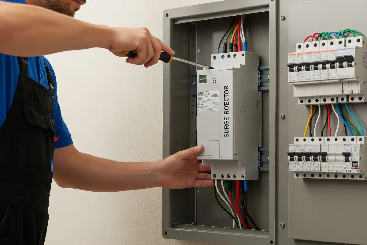
Surge Protective Device Supplier
Surge Protective Devices for Coordinated Transient Protection
Select an SPD from the power system, installation position, lightning exposure, required test class, maximum continuous operating voltage and downstream equipment withstand. SENTOP supports AC and PV DC model matching, samples, OEM requirements and bulk supply.
What an SPD Does
Limit transient voltage and divert surge current
A surge protective device contains at least one non-linear component. During a transient overvoltage, it limits the voltage appearing across the protected installation and diverts surge current through the designed protection path.
An SPD is not a voltage regulator, circuit breaker or cure for every power-quality problem. Sustained overvoltage, overload, short circuit, undervoltage and poor earthing require their own protection and system measures.
Transient event
Lightning effects and switching operations can create short-duration overvoltages that exceed sensitive equipment insulation withstand.
Voltage limitation
The SPD's voltage protection level and installed connecting leads influence the stress that reaches downstream equipment.
Surge-current path
Correct bonding, conductor routing and earthing provide a short, low-impedance path for diverted surge current.
End-of-life control
Thermal disconnectors, status indication and suitable backup protection must be coordinated with the exact SPD and fault level.
SPD Selection Process
Choose from the system, location and protection objective
A correct RFQ connects the installation risk, supply topology, equipment withstand, SPD test class, voltage and current ratings, protection modes and disconnection requirements.
Need for protection
Review lightning exposure, overhead or underground supply, external lightning protection, switching sources, installation rules, equipment value and acceptable downtime.
AC or PV DC system
Confirm AC or DC, nominal and maximum operating voltage, frequency, phase arrangement, polarity, earthing topology and source behavior.
Installation position
Identify service entrance, main board, sub-distribution board, final equipment, PV combiner box or inverter location and the cable distance between stages.
Type 1, 2 or 3
Select the test class and surge-current capability from the expected stress, lightning protection zone and required coordination with upstream and downstream SPDs.
Uc and Up
Choose maximum continuous operating voltage for the actual system and keep the installed protection level compatible with equipment impulse withstand.
Protection modes
Confirm L-N, L-PE, N-PE, DC+-PE or other required modes, conductor arrangement, poles and whether the selected assembly covers every necessary path.
Disconnection and status
Verify prospective short-circuit current, required fuse or circuit breaker, internal disconnector, remote contact, visual indicator, terminals, enclosure and certificate.
SPD Product Directions
Start with the power system and installation stage
These product directions organize an enquiry. Final selection depends on the exact model's Uc, Up, In, Imax or Iimp, modes of protection, short-circuit data, backup protection and certificate scope.
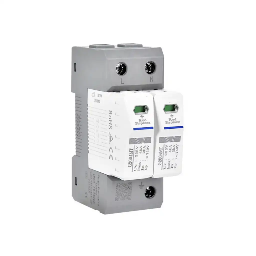
Type 2 AC SPD
A compact direction for distribution boards where line, neutral and PE protection modes must match the exact single-phase system.
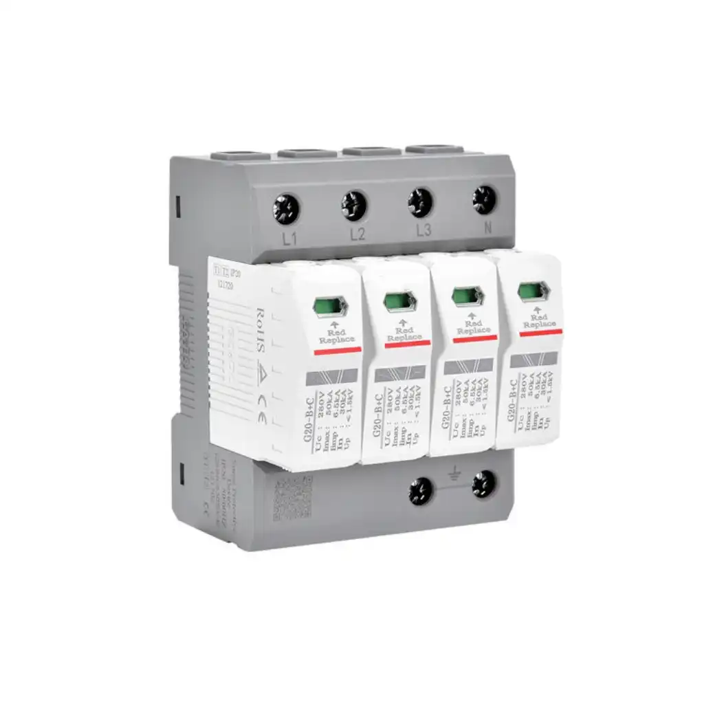
Three-Phase Type 1+2 SPD
A combined-duty direction for applicable three-phase service-entrance or main-board projects requiring declared Type 1 and Type 2 performance.
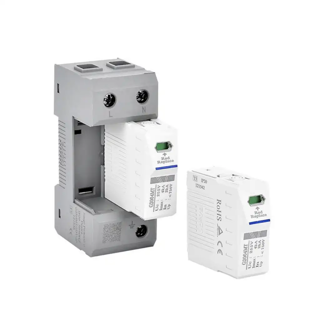
Pluggable Modular SPD
A replaceable-cartridge direction for panel builders and maintenance teams that need visual status indication and controlled module replacement.
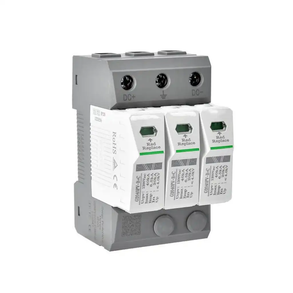
PV DC SPD
A dedicated DC direction for the PV array, combiner or inverter side. An AC SPD must not be substituted for a PV DC product.
Replacement reminder: send the complete model, front and side photos, AC or DC system, wiring diagram, Uc/Ucpv, Up, Type 1/2/3 marking, Iimp/In/Imax, poles, protection modes, backup device, terminals, dimensions and required certificate.
SPD Ratings That Work Together
Read voltage, current and test waveform together
Do not compare two SPDs by a single kA number. Type 1 and Type 2 ratings use different declared test quantities, while Uc, Up, short-circuit behavior and installation layout determine whether the product fits the system.
Maximum Continuous Operating Voltage
The maximum RMS AC or DC voltage that may be continuously applied to the SPD's mode of protection under declared conditions.
Voltage Protection Level
The declared limiting-voltage parameter used with equipment impulse withstand and installed lead voltage drop.
Nominal Discharge Current
A declared crest value of current through the SPD using the 8/20 current impulse for the applicable Type 1 or Type 2 test duty.
Impulse Discharge Current
A Type 1 SPD parameter representing the declared impulse current capability under the 10/350 current waveform.
Imax is a maximum discharge-current parameter using the 8/20 waveform for Type 2 products. It is not interchangeable with Type 1 Iimp. Always compare the same test class, waveform, mode of protection and complete product data.
SPD Standards and Application Scope
Verify the standard for the actual system and product
The standard number, edition and certificate must belong to the exact model. AC power, PV DC, product testing, installation selection and lightning protection measures have different scopes.
IEC 61643-01:2024
Contains common requirements for SPDs connected to circuits or equipment up to 1,000 V AC or 1,500 V DC within its scope.
IEC 61643-11:2025
Specifies AC low-voltage SPD requirements and test methods and is applied together with the latest IEC 61643-01.
IEC 61643-12:2020
Describes principles for selection, operation, location and coordination of SPDs on applicable 50/60 Hz AC power circuits.
IEC 61643-31:2018
Covers SPDs dedicated to the DC side of photovoltaic installations up to 1,500 V DC within its stated scope.
IEC 61643-32:2017
Provides selection, installation and coordination principles for SPDs used on the DC side of PV installations.
IEC 62305-4:2024
Addresses surge protection measures for electrical and electronic systems within structures as part of protection against lightning electromagnetic impulse.
SPD Installation and Coordination
The right product can underperform with the wrong connection
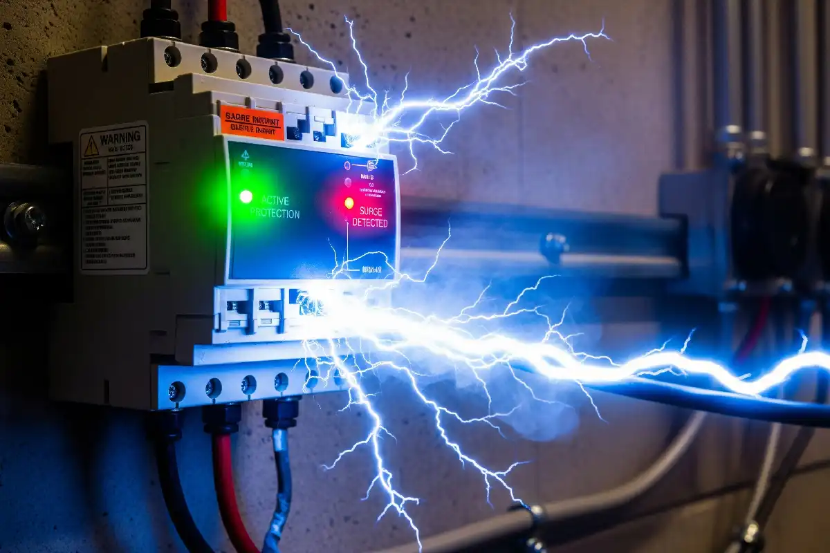
Keep the surge-current path short and direct, use the wiring arrangement declared for the product and coordinate every protection stage with the installation design.
SPD Quotation Checklist
Send the system and installation data for a faster quotation
You can begin with an existing model, nameplate photo, one-line diagram, equipment manual or basic supply information. We will identify the remaining details that require confirmation.
Describe the system
AC or PV DC, nominal and maximum voltage, frequency, phase, earthing topology, external LPS, one-line diagram and destination.
Define SPD duty
Installation position, Type 1/2/3, Uc or Ucpv, Up, Iimp/In/Imax, poles, protection modes and backup device.
Confirm the order
Existing sample, certificate, terminals, module width, remote contact, quantity, OEM label, packaging and delivery schedule.
Common SPD Specification Errors
Avoid a correct-looking product in the wrong electrical system
The most costly mistakes often come from mixing test classes, choosing Uc from nominal voltage only or overlooking the installed conductor path and backup protection.
SPD Model Verification and Bulk Supply
Build repeat orders around an approved surge specification
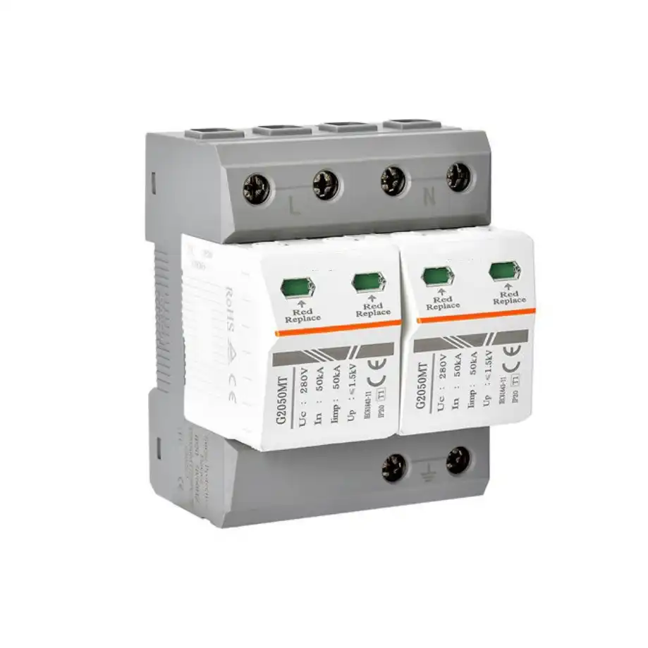
For panel builders, equipment manufacturers and distributors, a stable SPD order depends on configuration control. Similar housings do not prove identical surge-current capability or voltage protection.
Related Low-Voltage Protection
Continue planning the complete distribution system
Surge Protective Device FAQ
SPD selection questions
Use these answers to prepare the technical information required for model matching, replacement and procurement.
What is a surge protective device?
A surge protective device contains at least one non-linear component and is intended to limit transient overvoltages and divert surge currents. It must be selected and installed as part of a coordinated power and earthing system.
What is the difference between Type 1, Type 2 and Type 3 SPDs?
Type 1 SPDs are tested with impulse current Iimp and address severe service-entrance duty where partial lightning current may be present. Type 2 SPDs use Type 2 discharge-current tests for distribution protection. Type 3 provides supplementary protection near equipment and requires upstream coordination.
What is a combined Type 1+2 SPD?
A combined Type 1+2 SPD is one tested assembly with declared Type 1 and Type 2 performance. Confirm Iimp, In, Up, Uc, modes of protection, follow current and backup protection for the exact model.
What do Uc and Up mean on an SPD?
Uc is the maximum continuous operating voltage for the declared mode of protection. Up is the voltage protection level. Uc must fit the actual system, while Up and installed lead voltage must coordinate with downstream equipment withstand.
What is the difference between In, Imax and Iimp?
In is nominal discharge current using an 8/20 impulse. Imax is a maximum Type 2 discharge-current parameter using 8/20. Iimp is a Type 1 impulse-current parameter using 10/350. They cannot be compared as the same kA rating.
Can an AC SPD be used on a photovoltaic DC circuit?
Not unless the exact product is specifically designed, tested and marked for that DC application. PV DC SPDs require suitable Ucpv, polarity, protection modes, DC fault behavior and IEC 61643-31 scope.
Does an SPD protect against sustained overvoltage?
An SPD is intended primarily for transient overvoltage protection. Sustained or temporary overvoltage, overload, short circuit and other power-quality conditions require appropriate system protection and must be considered when selecting SPD Uc and TOV performance.
Why must SPD connecting leads be short?
Surge current changes rapidly, so conductor inductance creates additional voltage across long or looped leads. Short, direct connections and proper bonding help keep the installed protection level close to the design target.
Does an SPD need a fuse or circuit breaker?
The exact model may require coordinated backup overcurrent protection depending on its internal disconnector, short-circuit rating and system fault level. Use only the manufacturer-declared fuse or circuit-breaker range and wiring arrangement.
When should an SPD cartridge be replaced?
Replace the approved cartridge or complete SPD when its status indicator or remote contact shows end of life, after damage, or as required by inspection policy. Isolate the circuit and follow the product instructions.
Can SENTOP support OEM and bulk SPD orders?
Eligible SPD configurations can be reviewed for samples, model matching, labels, packaging, documentation, spare cartridges, remote-contact options and repeat supply. Feasibility and approval scope are confirmed for the requested model and destination.
SPD Supply Support
Send your one-line diagram, system voltage or existing SPD model
SENTOP can review surge protective device requirements for AC distribution, PV DC systems, replacements, samples, OEM panels, distributor ranges and bulk orders.
