
DC Isolator Switch Supplier
DC Isolator Switches for Safe, Visible Circuit Separation
Select a DC isolator or switch-disconnector from the maximum system voltage, operational current, required load-switching duty, pole arrangement, installation method and environmental conditions. SENTOP supports photovoltaic, battery, industrial DC, OEM panel and bulk-supply requirements.
Function Before Product
Separate a DC circuit, then confirm whether it must break load current
A DC isolator provides a defined isolation function so equipment can be separated from an energized source for maintenance. A switch-disconnector combines isolation with a declared making and breaking capability under specified utilization conditions.
The two terms are often used loosely in the market, but their duties are not interchangeable. The exact product data must show whether the device may operate under load, at what DC voltage and current, and with which contact wiring.
Isolation function
Provides a defined open state for maintenance when installed and operated according to the product instructions and system procedure.
Load switching
Requires a switch-disconnector with a declared DC utilization category and operational current for the actual voltage and circuit.
Fault interruption
A DC isolator is not automatically an overcurrent protective device. Short-circuit protection must be provided and coordinated separately unless expressly integrated.
Visible operating state
Rotary handles, position indication and lockable OFF arrangements can support safe operating procedures, subject to the exact model design.
DC Isolator Selection Process
Match the device to the real DC circuit
A current value on the front label is not enough. DC arc extinction depends on voltage, current, contact spacing, contact stages and the manufacturer's tested wiring arrangement.
Identify the DC source
State whether the circuit is photovoltaic, battery, rectifier, telecom, transport or industrial DC, because voltage behavior and fault energy differ.
Use maximum voltage
For PV, consider maximum array open-circuit voltage at the minimum design temperature. For other systems, use the highest credible operating and charging voltage.
Define switching duty
Confirm whether the device is operated only after current is removed or must make and break load current under a declared category such as DC-PV2.
Calculate operational current
Include continuous load, PV string or array current, overload expectations, enclosure temperature, grouping and model-specific derating.
Confirm poles and contact stages
Specify which positive and negative conductors are switched and follow the exact series or parallel contact wiring shown for the selected model.
Coordinate fault protection
Verify prospective short-circuit current, upstream fuse or breaker, conditional short-circuit data and required protection of conductors and equipment.
Choose the installation format
Match DIN rail, panel mounting, door coupling, enclosed outdoor mounting, equipment integration, terminal access and available space.
Verify environment and approvals
Review IP rating, temperature, altitude, UV exposure, pollution degree, lockability, terminals, standards and target-market documentation.
DC Isolator Product Directions
Choose the format from the installation and switching duty
These directions organize an enquiry. Final performance must be confirmed from the exact model datasheet, wiring diagram, markings and certificate scope.
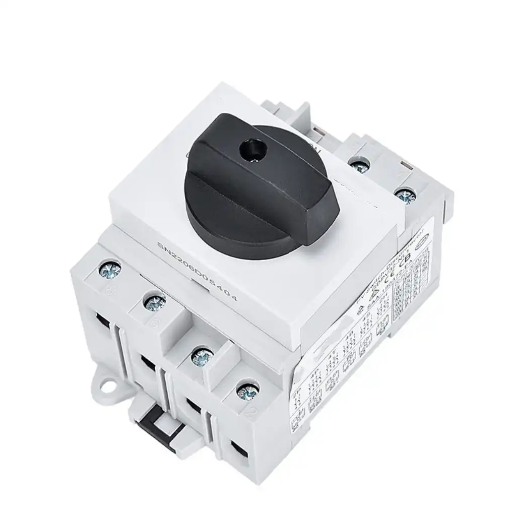
DIN Rail DC Switch-Disconnector
A compact direction for combiner boxes, inverter input cabinets and industrial DC panels where accessible modular mounting is required.
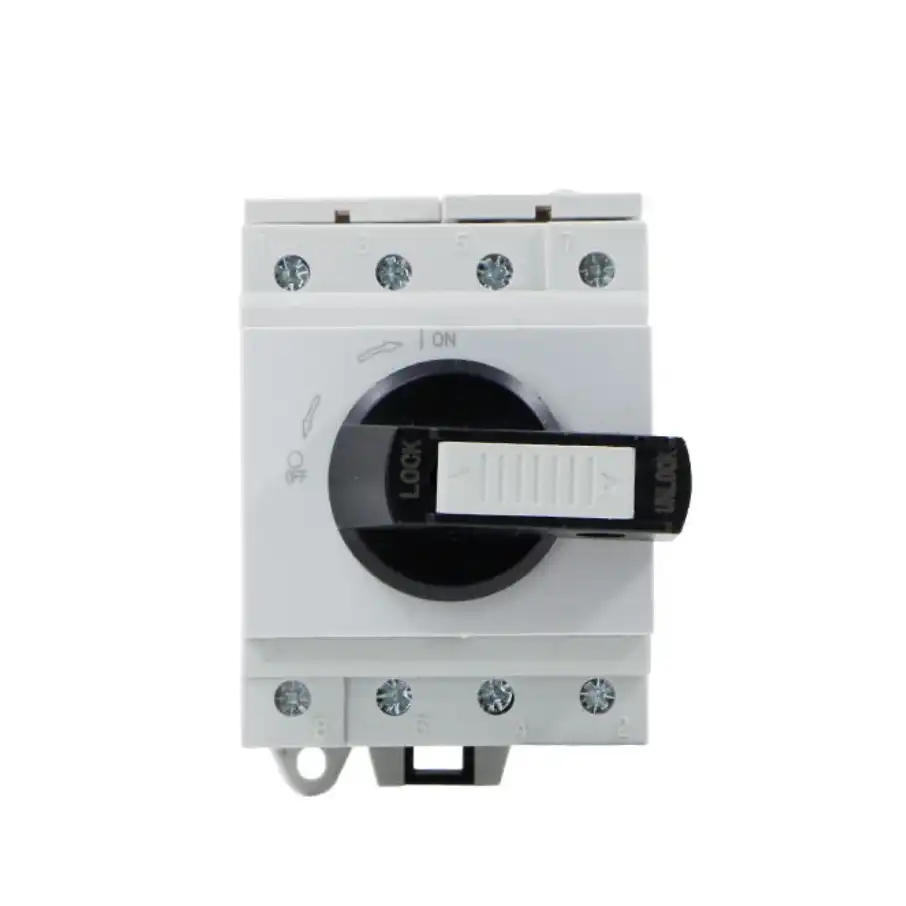
Panel-Mounted Rotary DC Isolator
A front-operated direction for machinery, electrical enclosures and local disconnection points where clear ON/OFF operation is important.
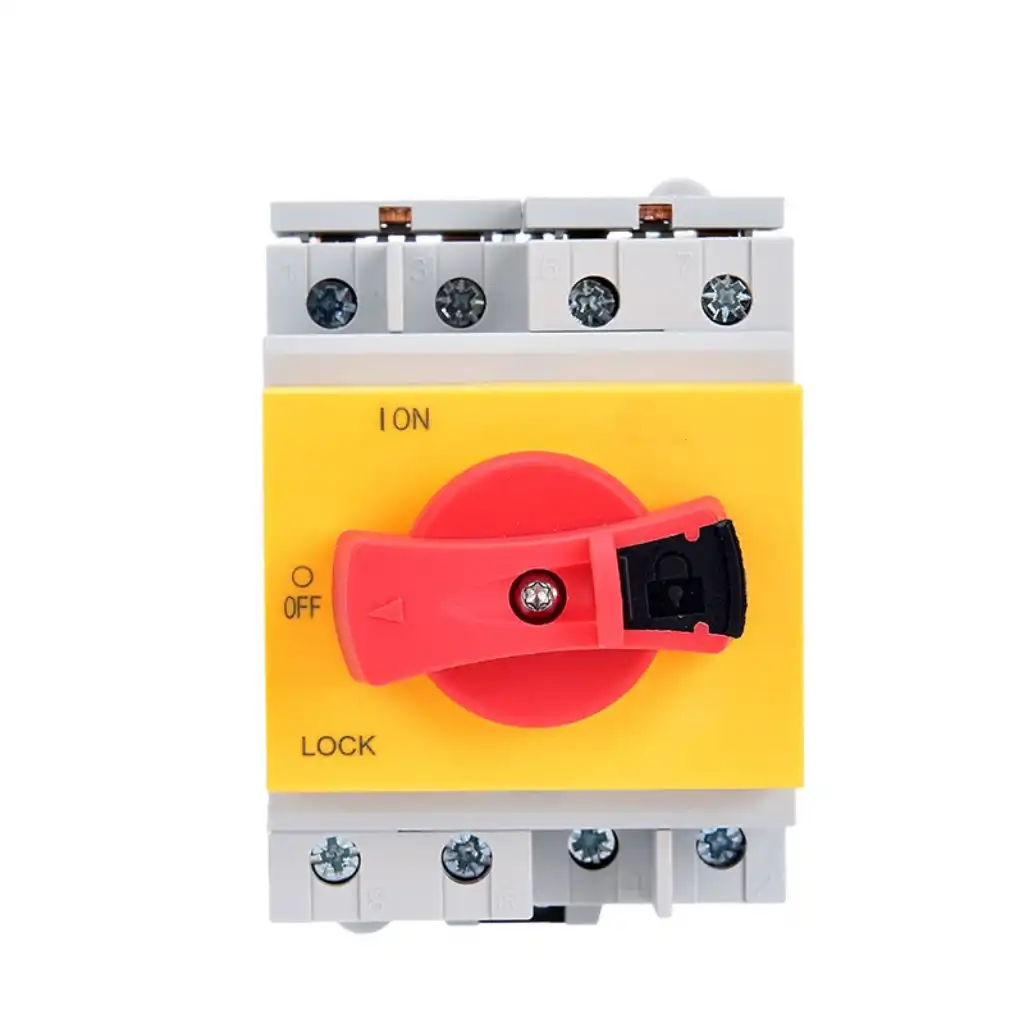
Padlockable DC Isolation Switch
A maintenance-focused direction where a clear OFF position and provision for lockout are required in the operating procedure.
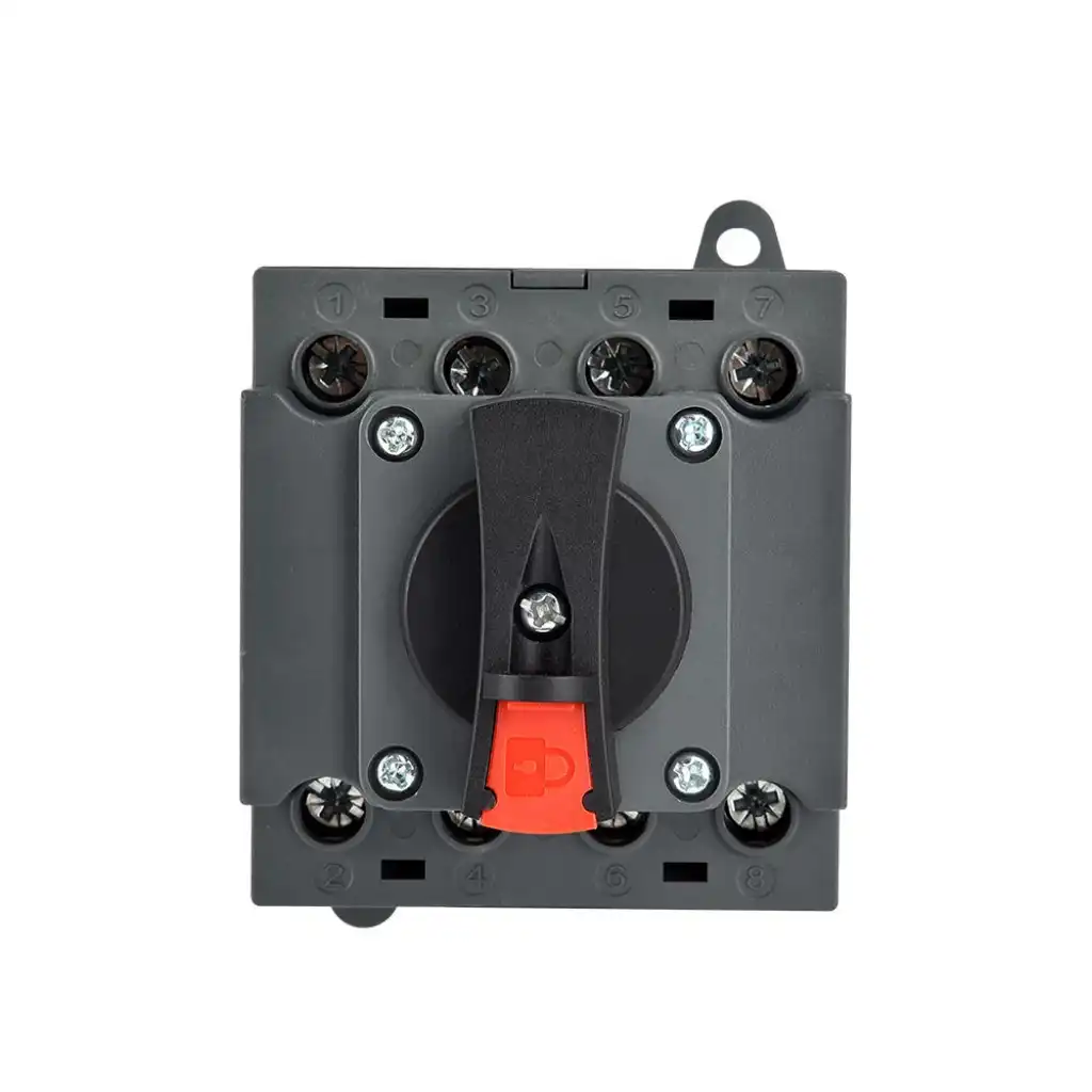
Multi-Pole DC Isolator Assembly
A four-pole direction for higher-voltage contact series arrangements, multiple conductors or project-specific industrial switching schemes.
Important: similar-looking isolators can have different voltage tables, wiring diagrams and load-breaking duties. Order from the exact model code and approved documentation, not from appearance alone.
DC Switching Data
The ratings that determine usable performance
DC current does not pass through a natural current zero on every half cycle as AC does. Contact opening, arc length and the complete contact path are therefore central to safe switching.
Maximum declared DC voltage
Use the product's rated operational voltage for the exact contact arrangement and utilization category.
Current under stated conditions
Operational current depends on the switching category, voltage, ambient conditions and product construction.
Declared load-switching duty
Categories such as DC-PV2 define application-specific operating conditions. A thermal current marking alone does not prove load-break capacity.
Poles and series contacts
Multiple contacts may be placed in series to interrupt a higher DC voltage. Wiring must follow the exact manufacturer diagram.
Also verify rated insulation voltage, impulse withstand voltage, conditional short-circuit current, required backup device, mechanical/electrical endurance, terminal capacity and temperature limits for the exact model.
Standards and Documentation
Confirm the standard scope against the complete application
A standard number on a catalogue does not automatically confirm every voltage, current, utilization category, enclosure or target-market requirement.
IEC 60947-3
Covers low-voltage switches, disconnectors, switch-disconnectors and fuse-combination units. Review the exact device function, utilization category and declared ratings.
IEC 60947-1
Provides general rules for low-voltage switchgear and controlgear, including referenced definitions, characteristics and test conditions used by product standards.
IEC 62548-1
Addresses photovoltaic array design requirements including DC wiring, switching, earthing and isolation provisions within the complete PV array.
IEC 60364-7-712
Applies to low-voltage photovoltaic power-supply installations. Device selection must fit the installation architecture and local rules.
Datasheet and test scope
Verify model code, voltage/current table, wiring diagram, utilization category, certificate owner, report scope, markings and production identity.
Local code and approvals
Confirm required national standards, installer rules, labels, language, enclosure, disconnect location and authority acceptance before ordering.
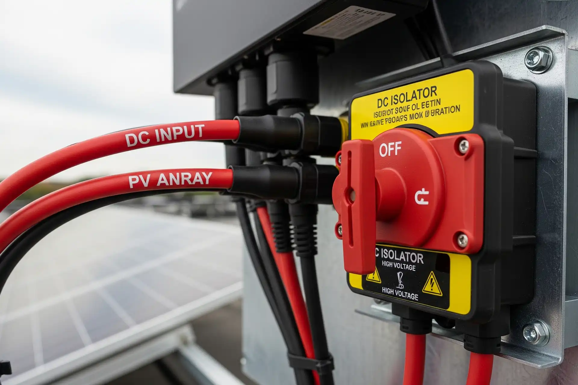
Application Directions
Place isolation where the system and service procedure need it
The device is one part of the DC system. Cable protection, overcurrent protection, earthing, inverter or battery instructions, emergency procedures and access must be coordinated with it.
Prepare a Useful Enquiry
Three items make DC isolator matching faster
Send the electrical source data, switching requirement and installation conditions together. Photos of an existing label and terminal diagram are useful for replacements.
Source and ratings
Application, nominal and maximum DC voltage, operational current, number of strings or feeds, poles, prospective fault current and existing protection.
Required function
Isolation only or load breaking, operating frequency, utilization category, conductor arrangement, terminal diagram and lockout requirement.
Installation and supply
DIN rail, panel or enclosure, IP rating, temperature, cable size, dimensions, approvals, quantity, destination, packaging and delivery schedule.
Installation and Operation
Control the DC arc with the correct device and wiring
Installation, testing and maintenance should be completed by qualified people using the product instructions and site safety procedure.
OEM, Replacement and Bulk Supply
Keep the approved electrical identity consistent
SENTOP can support model review, samples, eligible private-label requirements, packaging and repeat procurement for distributors, panel builders, inverter suppliers and equipment manufacturers.
Related DC and Panel Products
Plan the complete electrical path
DC Isolator Switch FAQ
Buyer and installation questions
Use these answers to define the circuit before requesting an exact model, replacement or OEM configuration.
What is a DC isolator switch?
A DC isolator is a manually operated device used to separate a DC circuit for maintenance. If the product is also a switch-disconnector, it may make and break specified load current under its declared DC utilization category and ratings.
Is a DC isolator the same as a DC circuit breaker?
No. An isolator provides circuit separation and may have declared load-switching capability, while a DC circuit breaker is intended to interrupt specified overcurrent or short-circuit conditions. The isolator normally requires coordinated upstream protection.
Can every DC isolator switch current under load?
No. Load interruption is allowed only when the exact device is declared as a switch-disconnector for the applicable DC voltage, current, utilization category, contact arrangement and operating conditions.
What does DC-PV2 mean?
DC-PV2 is a photovoltaic DC utilization category used for switch-disconnectors intended to make and break circuits where substantial overcurrents may occur. Confirm the exact product's declared voltage, current and test scope.
How do I choose the voltage rating for a PV DC isolator?
Use the maximum array open-circuit voltage under the minimum design temperature, not only the nominal operating voltage. Then confirm that value against the exact contact wiring and rated operational voltage table.
How do I choose the current rating?
Determine the circuit design current from the source and load, then apply the relevant PV, installation, enclosure, ambient-temperature and manufacturer derating factors. Check operational current at the selected voltage and category.
Why are multiple poles or series contacts used in DC isolators?
Placing contacts in series increases the total open contact distance and can help extinguish a higher-voltage DC arc. The terminal links and conductor path must follow the exact approved wiring diagram.
Can an AC isolator be used on a DC circuit?
Only when the exact product has a declared DC rating for the required voltage, current, duty and wiring arrangement. An AC-only rating must not be assumed suitable because DC arcs behave differently.
Where should a PV DC isolator be installed?
The location depends on the PV array and inverter design, local installation rules, accessibility and equipment instructions. It may be near the array, combiner, inverter or integrated into equipment, with suitable enclosure and cable routing.
When should a DC isolator be inspected or replaced?
Inspect according to the installation and maintenance plan and after abnormal events. Replace a device with heat damage, loose or damaged terminals, moisture ingress, cracked housing, unreliable operation, unreadable markings or performance outside the approved model condition.
Can SENTOP support OEM and bulk DC isolator orders?
Eligible configurations can be reviewed for model matching, samples, labels, packaging, instructions, terminal arrangements, enclosure integration and repeat supply. Feasibility and approval scope are confirmed for the requested model and destination.
DC Isolation Supply Support
Send the maximum DC voltage, current and contact diagram
SENTOP can review DC isolator and switch-disconnector requirements for photovoltaic systems, battery equipment, industrial DC panels, replacements, samples, OEM assemblies and bulk orders.
