

Electrical Components for Solar & Energy Systems
Organize DC isolation, surge protection, distribution, power transfer, measurement and panel wiring around the actual architecture of a photovoltaic, storage or hybrid-energy project.
Place each electrical component where its duty begins
A useful component list starts with the one-line diagram. Each stage changes the voltage, current direction, switching duty, protection requirements and information needed for model selection.
PV Array
Confirm string configuration, maximum open-circuit voltage and operating current at site conditions.
DC Collection
Organize string circuits, combiner wiring, terminal points and enclosure interfaces.
Isolation & SPD
Match DC switching and surge protection to voltage, polarity, location and coordination.
Power Conversion
Define inverter, charger or converter interfaces without substituting for equipment approvals.
AC Distribution
Coordinate distribution, switching, transfer and auxiliary control products at system voltage.
Metering & Control
Confirm measured quantities, CT or direct input, communication and monitoring integration.
Different energy architectures create different electrical priorities
Select the closest project type to see which data should be confirmed before requesting components.
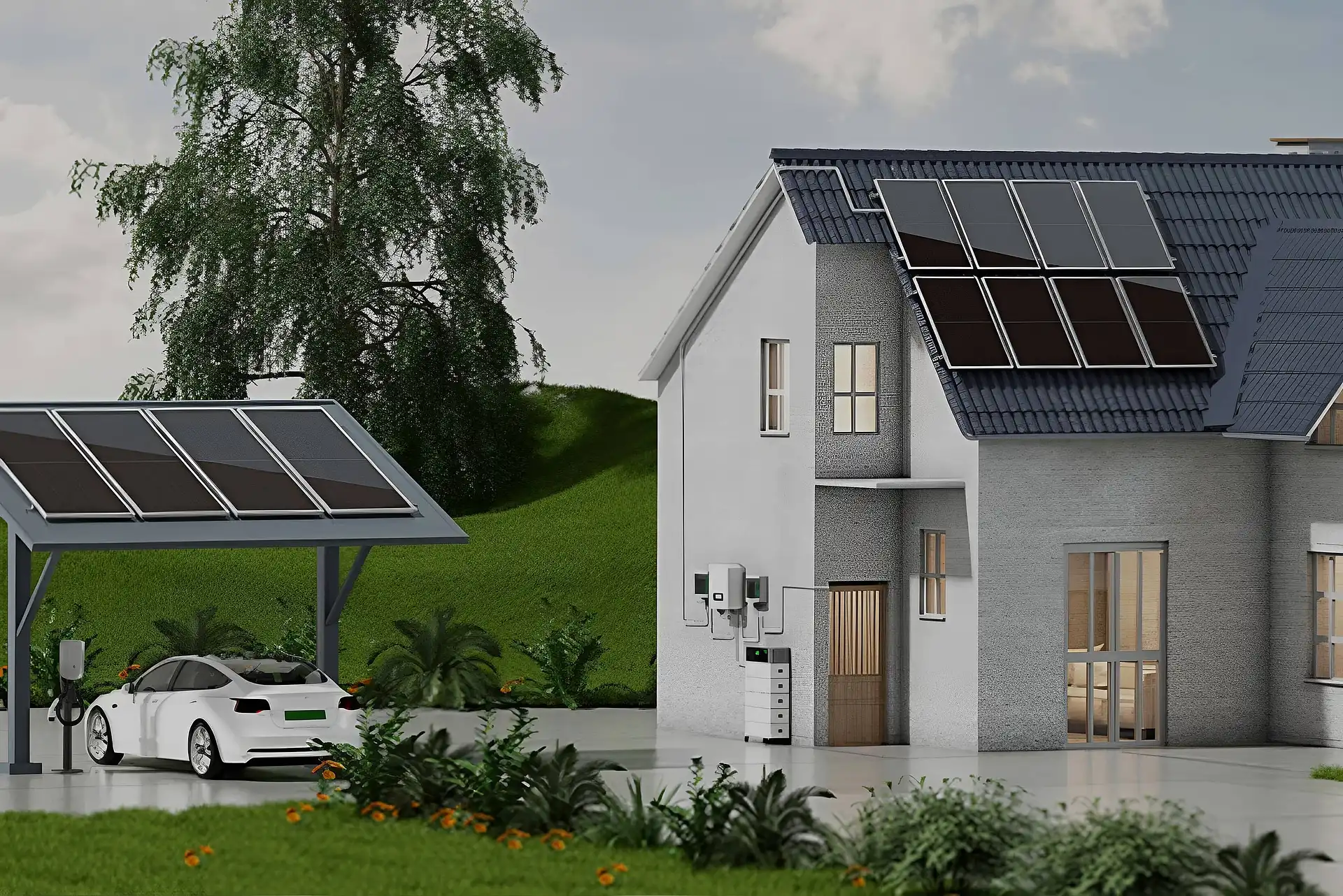
Grid-connected photovoltaic system
Coordinate the PV DC side, inverter interface, AC distribution and metering with the installation design and local grid-connection requirements.
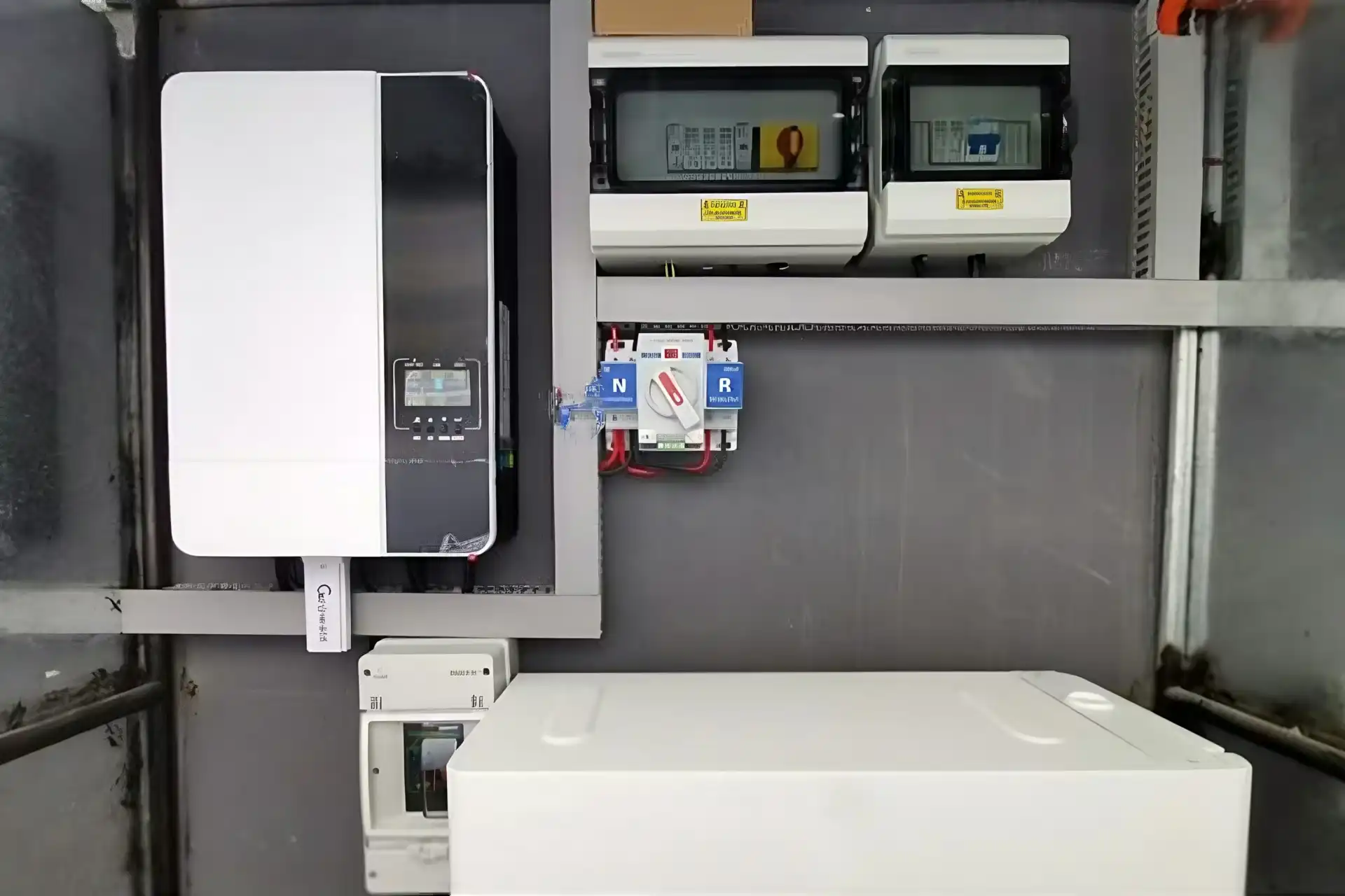
Photovoltaic system with battery energy storage
Battery circuits can introduce bidirectional current, different isolation arrangements and fault-energy conditions that must be reviewed with the battery and power-conversion equipment.
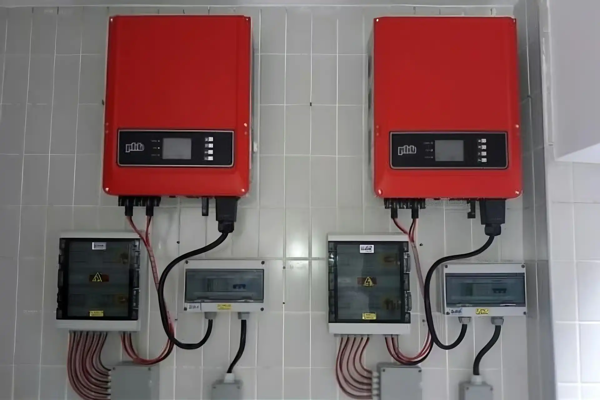
Utility, solar, storage and generator backup
Hybrid systems require a defined source hierarchy, interlocking method and transfer sequence so that power sources cannot be connected in an unintended condition.
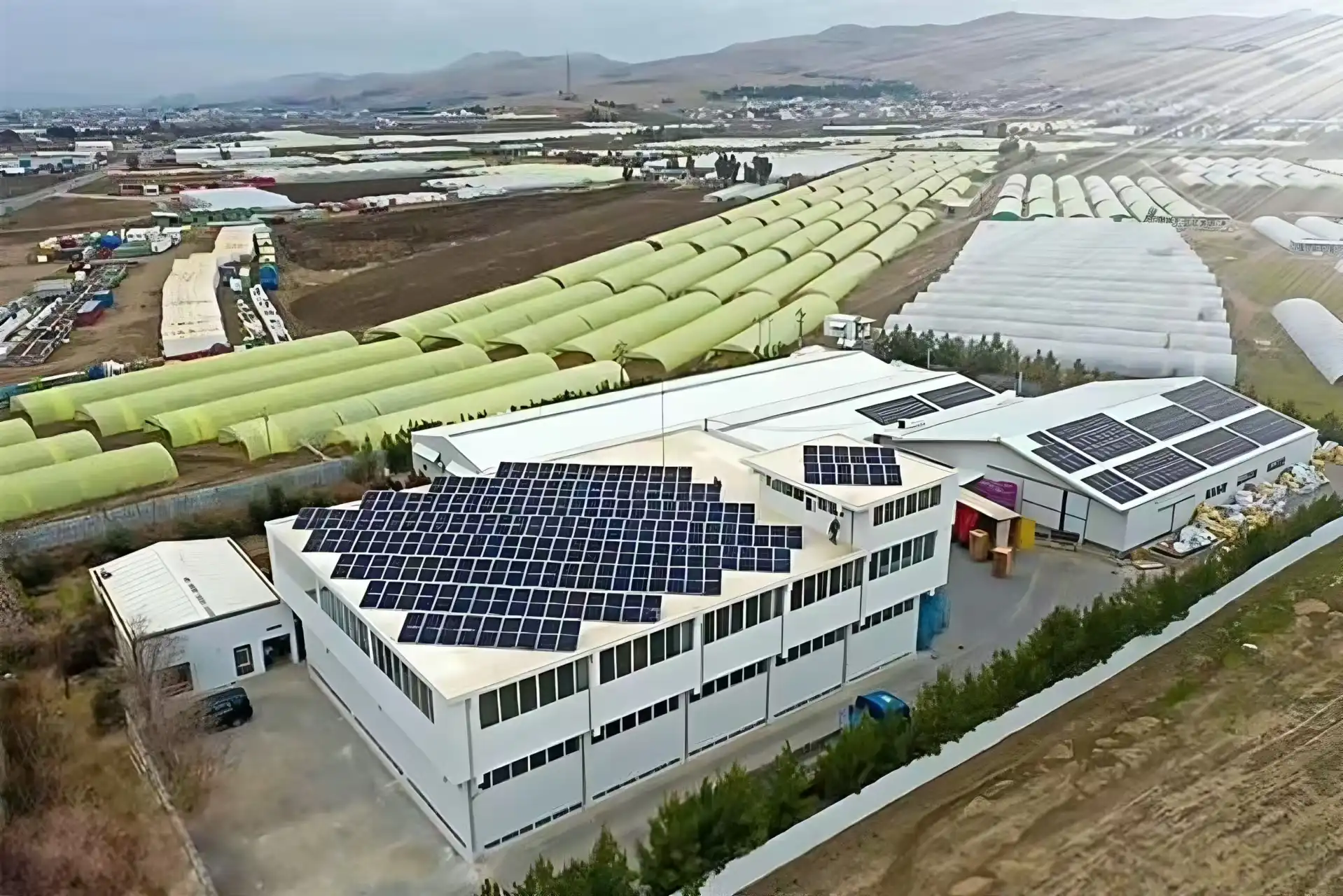
Distributed and remote energy equipment
Remote sites place greater emphasis on environmental protection, service access, spare strategy, communication and clear field identification.
Build the package around electrical duty
The products below solve different parts of the system. Their ratings and documentation must agree with the same project architecture.
PV DC Isolation
Provide a defined means of isolation for maintenance or emergency procedures. Confirm maximum system voltage, current, poles, polarity, utilization category, enclosure and mounting.
Review DC isolator switchesPV Surge Protection
Match the SPD to the PV DC voltage, earthing arrangement, installation location, protection level and coordination. The AC and DC sides are separate selection tasks.
Review surge protective devicesTransfer Switching
Coordinate utility, generator, inverter or storage sources according to the operating sequence, neutral arrangement, current, poles, interlocking and control ownership.
Review automatic transfer switchesSimilar appearance does not mean equal system duty
Energy-system components must be evaluated by ratings, standards, application conditions and integration data. These are common reasons a quotation or replacement needs further review.
Using an AC device on the PV DC side
DC interruption and isolation behavior depend on voltage, polarity, contact arrangement and utilization duty. An AC label or similar enclosure is not evidence of PV DC suitability.
Selecting from nominal voltage instead of maximum design voltage
PV open-circuit voltage changes with module count and temperature. Selection should use the calculated maximum system condition and applicable design margins.
Treating every surge protector as interchangeable
SPD type, maximum continuous operating voltage, protection level, short-circuit coordination and earthing arrangement must suit the installation point.
Ignoring the source sequence in a hybrid system
Utility, generator, inverter and storage sources require a clear transfer and interlocking strategy. The component cannot correct an undefined operating sequence.
Ordering a meter without its input system
Confirm direct input or CT input, CT ratio, measured quantities, auxiliary supply, dimensions, communication protocol and register requirements together.
Quoting terminals without the complete strip BOM
Terminal bodies, PE positions, bridges, markers, end plates, end clamps and DIN rail should be reviewed as one installed assembly.
Site conditions belong in the component specification
Solar and energy equipment is often installed outdoors, on rooftops or in remote cabinets. Share the real environment so the enclosure, terminals, switching and protection package can be reviewed as an installed system.
Coordinate the BOM before confirming models
A complete enquiry reduces model changes and makes it easier to check interfaces between isolation, protection, transfer, metering and wiring products.
| Data group | What to provide | What it helps confirm |
|---|---|---|
| System architecture | One-line diagram, source list, power flow, grid, inverter, storage and generator interfaces | Component location, switching sequence, isolation boundaries and measurement points |
| DC electrical data | Maximum voltage, Isc, operating current, polarity, string count, battery and PCS data | DC isolator, SPD, terminals, conductor interfaces and enclosure arrangement |
| AC electrical data | Voltage, frequency, phases, neutral, load current, fault level and distribution method | Transfer switch, breakers, contactors, metering and auxiliary power selection |
| Monitoring and controls | Measured quantities, CT data, protocol, register needs, I/O and control ownership | Panel-meter input, communication, auxiliary supply and control interfaces |
| Installation conditions | Indoor or outdoor, temperature, altitude, IP target, material, cable entries and mounting | Enclosure, derating, access, mechanical fit and environmental suitability |
| Commercial requirements | Quantity, destination, target market, approvals, labels, packaging and delivery schedule | Applicable model range, documentation, samples and production preparation |
For a replacement: include clear front, side, label and terminal photos together with dimensions and the original circuit location. A family name alone is rarely enough for an exact match.
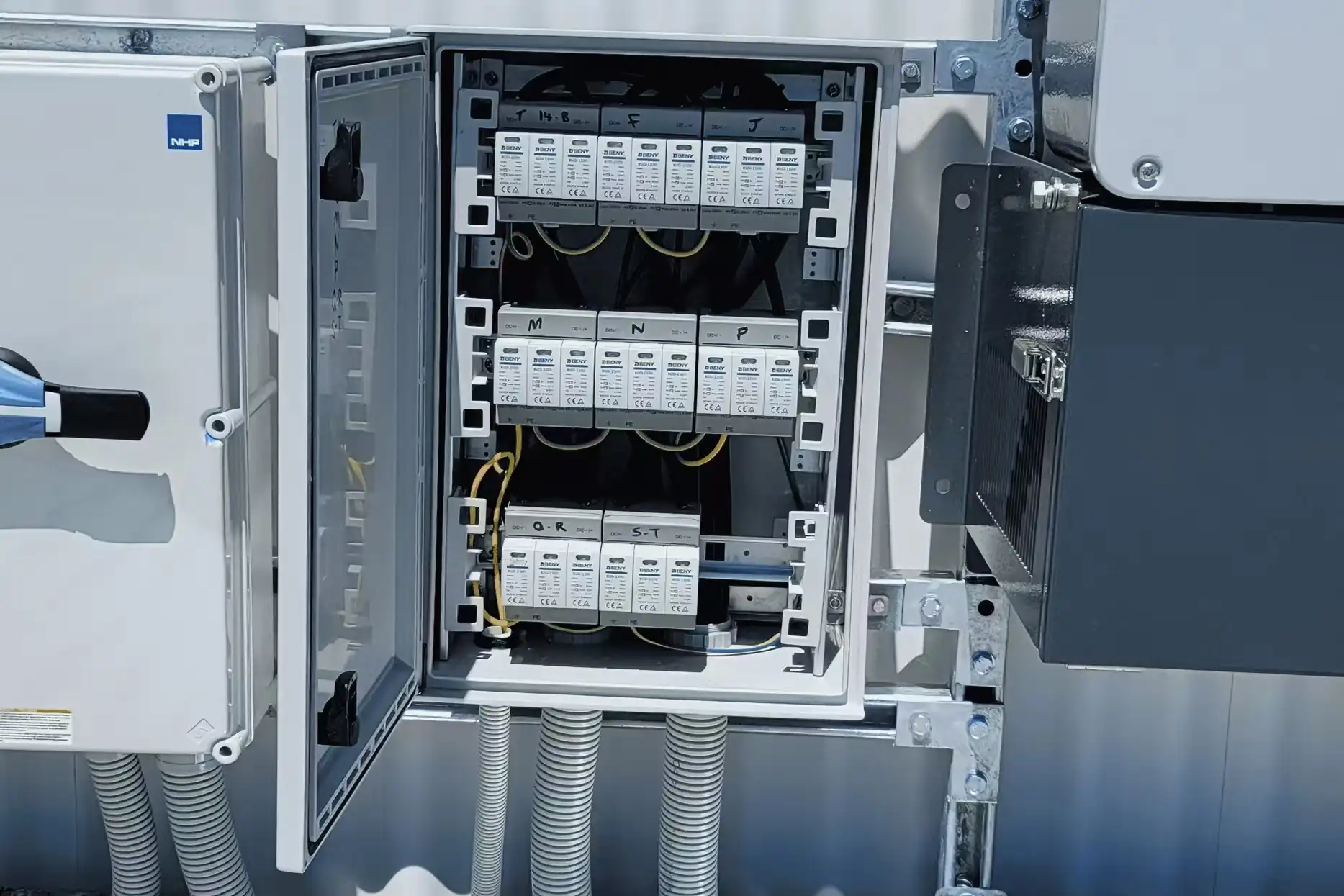
Keep electrical interfaces and purchasing data aligned
SENTOP can review selected electrical components as one purchasing package while keeping the boundary between component supply and system engineering clear.
Use the current project standard and exact product documentation
Standards define system-level requirements, while product suitability must still be confirmed for the exact model, rating, installation and target market.
Addresses photovoltaic array design, including DC wiring, protection, switching and earthing provisions.
View the IEC publicationApplies to electrical installations of PV systems from the modules to the connection point and includes relevant energy-storage considerations.
View the IEC publicationSets requirements and test methods for SPDs used on the DC side of photovoltaic installations up to 1500 V DC.
View the IEC publicationCovers selection, installation and coordination principles for SPDs connected to photovoltaic installations.
View the IEC publicationShare the system data before requesting exact models
Send what is available. A one-line diagram, product reference or cabinet photo can be reviewed together with the key electrical and commercial information.
Questions buyers ask before component selection
Use these answers as a starting point, then confirm the exact project data and applicable requirements.
Which SENTOP products are relevant to solar and energy systems?
Depending on the architecture, the component package can include DC isolator switches, surge protective devices, transfer switches, digital panel meters, terminal blocks, selected circuit breakers, distribution boxes, power supplies and contactors. The exact scope starts from the one-line diagram.
Can SENTOP design the complete photovoltaic or battery system?
SENTOP supports electrical component selection and coordinated purchasing. PV module selection, inverter and battery controls, grid studies, protection coordination, system engineering and installation approval remain with the responsible designers, equipment manufacturers and qualified installers.
How do I choose a DC isolator for a PV array?
Provide the calculated maximum DC voltage, operating and short-circuit current, number of poles, polarity, switching duty, mounting arrangement, enclosure and applicable product standard. The device must be evaluated for the exact DC application.
Can an AC surge protector be used on the PV DC side?
Do not assume so. The DC side requires a product with suitable PV DC ratings, topology, maximum continuous operating voltage, short-circuit behavior and coordination for the installation. Review the exact product documentation.
What changes when battery storage is added?
Battery storage may add bidirectional power flow, a different maximum DC voltage, higher available fault energy, BMS and PCS interfaces, new isolation points and additional source-transfer logic. Supply the battery and conversion-equipment data with the one-line diagram.
When is a transfer switch used in a solar or hybrid system?
A transfer switch can be part of a system that changes between utility, generator, inverter or another approved source. The operating sequence, neutral treatment, interlocking, poles, current, controller ownership and source compatibility must be defined first.
What information is needed for a digital panel meter?
Confirm measured quantities, AC or DC input, direct or CT input, CT ratio, auxiliary supply, panel cutout, accuracy requirements, alarm outputs and communication protocol. Include the intended controller or monitoring-system details where applicable.
Can I request one combined BOM for several product categories?
Yes. Send the one-line diagram, model references, ratings, quantities, destination, target market, required documentation, packaging and delivery needs. SENTOP can organize selected component groups under one project reference for review.
Turn your solar or energy one-line diagram into a clearer component enquiry
Send the available ratings, equipment references, installation conditions, quantity and destination. We will help organize the next component-matching step.
