

Screw Terminal Blocks for Secure Industrial Wiring
Source UK, UT, TB, TBC, X3 and X5 screw terminal blocks for control panels, power equipment, machinery and OEM assemblies. SENTOP supports model matching, compatible accessories, replacement review and organized bulk supply.
What is a screw terminal block?
A screw terminal block creates a detachable electrical connection by tightening a screw-driven clamp onto a prepared conductor. The familiar connection process makes screw terminals widely used in control cabinets, industrial machinery, power equipment, distribution assemblies and serviceable OEM products.
The correct terminal is selected from the complete system, not from appearance alone. Conductor construction, cross-section, electrical rating, pitch, mounting method, tightening requirement, insulation structure and accessory compatibility must all match the application.
Prepare the conductor
Use the stripping length and conductor preparation specified for the selected model. Confirm whether a ferrule or other terminal preparation is required.
Insert the wire completely
Place the conductor inside the intended clamp area without trapping insulation or leaving excessive bare copper exposed.
Tighten to the specified value
Use the tool and model-specific tightening torque stated in the product documentation. A universal torque value should not be assumed.
Inspect the finished connection
Verify wire retention, conductor position, terminal mounting, identification and any bridge or cover installation before energizing.
Choose the series by mounting and wiring task
Start with the equipment structure and conductor requirement. SENTOP can then narrow the model range and confirm dimensions, ratings, poles, accessories and packaging.
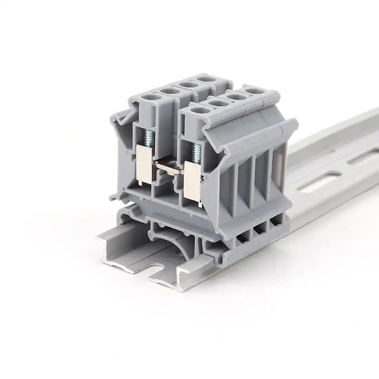
DIN Rail Screw Terminal Blocks
Modular terminal blocks for organized cabinet wiring. The range can support feed-through, protective earth, multi-level and selected functional positions when a coordinated terminal strip is required.
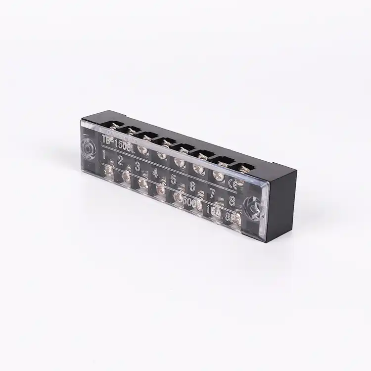
Barrier Screw Terminal Blocks
Separated screw positions for equipment, power supply and distribution wiring. Barrier structures provide clear pole separation, while selected models can be paired with protective covers and mounting hardware.
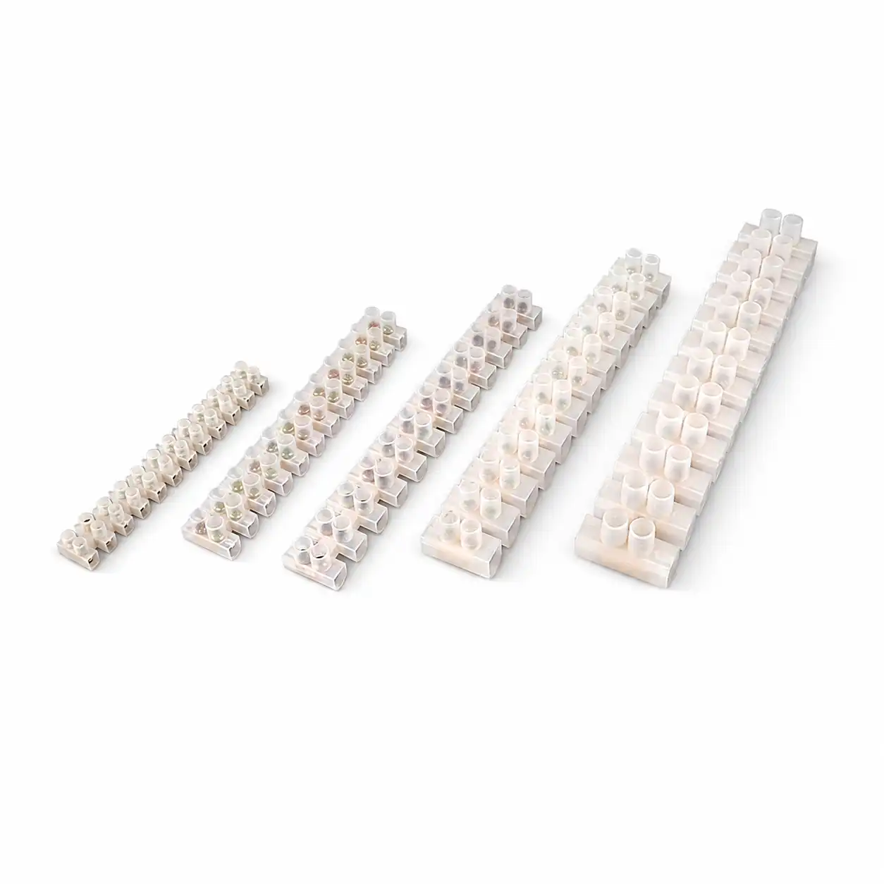
Compact Screw Terminal Strips
Compact multi-pole connection strips for appliances, lighting, control devices and space-conscious equipment wiring. Select the strip by pole count, conductor range, electrical requirement and fixing method.
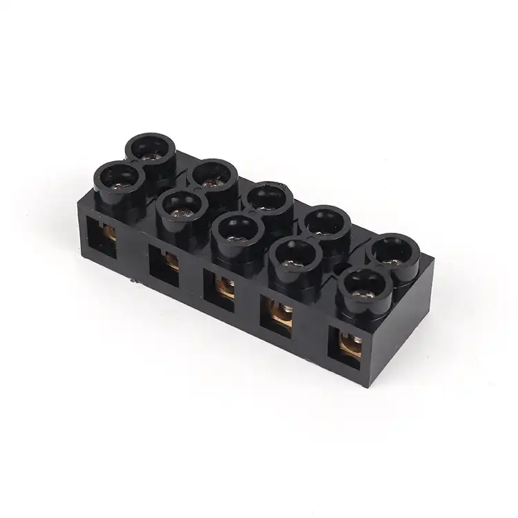
Multi-Position Screw Terminal Strips
Fixed screw terminal strips for organized line, load and equipment connections. Multiple position options help consolidate wiring while keeping each circuit accessible for assembly and maintenance.
Match the terminal block to the equipment layout
Mounting method affects panel layout, wiring access, service procedure and accessory selection. Confirm the physical installation before finalizing the series.
DIN Rail Mounting
Modular terminals clip onto a compatible rail and can be combined into marked terminal strips with end parts and bridges.
Typical direction: UK or UT modular seriesBarrier Structure
Insulating barriers separate adjacent screw positions for clear multi-pole equipment or distribution connections.
Typical direction: TB or TBC barrier seriesPanel or Direct Mount
The terminal strip is fixed to a panel, base or enclosure using the mounting provisions designed into the selected model.
Confirm hole spacing and installation clearanceCompact Equipment Strip
A small multi-pole format helps connect internal equipment wiring where rail installation is not required or space is limited.
Typical direction: X3 or selected X5 models
Order the connection system, not only the terminal
A correct terminal without compatible accessories can delay cabinet assembly. Send the strip drawing, circuit schedule or BOM so the full requirement can be reviewed together.
Confirm these parameters before requesting a quotation
Complete input reduces model revisions and helps align the terminal, accessories, installation and documents with the actual equipment requirement.
| Selection item | Information to provide | Why it matters | Helpful evidence |
|---|---|---|---|
| Existing series or model | Full model number, brand reference or BOM code | Provides a starting point for compatible supply or replacement review | Label photo, drawing or sample |
| Conductor | Solid or stranded wire, cross-section, ferrule and insulation diameter | Determines the suitable connection range and conductor preparation | Wire specification or cable datasheet |
| Electrical requirement | Operating current, voltage, circuit purpose and applicable standard | Guides rating and insulation coordination checks | Schematic or equipment specification |
| Poles and circuit layout | Number of positions, PE locations, bridges and grouped circuits | Defines the terminal strip arrangement and accessory quantities | Terminal plan or cabinet schedule |
| Mounting and dimensions | DIN rail profile, panel mounting, pitch, width, height and clearances | Ensures the product fits the rail, enclosure and wiring space | Dimensioned photo or installation drawing |
| Connection procedure | Stripping length, tool access and required tightening instructions | Supports a controlled assembly and inspection process | Work instruction or selected model datasheet |
| Accessories | End plates, clamps, covers, bridges, markers, rails and partitions | Prevents an incomplete or incompatible terminal system order | Accessory list or completed strip photo |
| Commercial data | Quantity, sample need, packaging, destination and requested documents | Supports accurate quotation, labeling and delivery planning | RFQ sheet or purchase specification |
Replacement reminder: Similar color and shape do not prove interchangeability. Compare the complete model code, dimensions, mounting foot, conductor range, rating, screw access and accessory interfaces before approving a substitute.
Screw clamp, spring cage or push-in: which fits your process?
The connection technology should match conductor preparation, assembly volume, installer procedure, maintenance access and the approved equipment design.
| Decision factor | Screw clamp | Spring cage | Push-in spring |
|---|---|---|---|
| Connection process | Screw is tightened to secure the prepared conductor | Spring is opened before conductor insertion | Compatible prepared conductors may be inserted directly |
| Assembly control | Requires the correct tool and model-specific tightening procedure | Requires the specified spring operating method | Depends on conductor stiffness, ferrule and model design |
| Service access | Screw is loosened for conductor removal | Operating slot or button releases the spring | Release method depends on the selected model |
| Common starting point | Established screw-clamp standards, replacement work and installer preference | Mixed conductor needs and tool-operated spring preference | Repeated cabinet wiring with controlled conductor preparation |
| Key verification | Torque, conductor position, stripping length and inspection plan | Supported conductors and operating tool | Direct-insertion conductor types and release procedure |
The comparison describes connection processes, not universal performance. Electrical and mechanical suitability must be verified against the exact model documentation and application standard.
Select the terminal family from the actual wiring task
Application names are only a starting point. Use the circuit, conductor, mounting method, service environment and equipment layout to confirm a suitable screw terminal block.
Control panels and PLC cabinets
Organize field wiring, control power, relays, sensors and actuators into accessible and clearly marked terminal groups.
Typical direction: UK or UT DIN rail terminalsPower supplies and distribution units
Provide separated line, load and branch connection points inside power conversion or distribution equipment.
Typical direction: barrier or model-specific DIN rail seriesIndustrial machinery
Connect motors, switches, sensors, control components and serviceable machine modules using a familiar screw-clamp process.
Typical direction: DIN rail strip with markers and PE positionsOEM electrical equipment
Integrate fixed multi-pole connections into equipment bases, housings and assemblies with controlled dimensions.
Typical direction: TB, TBC, X3 or X5 by structureLighting and appliance wiring
Use compact terminal strips where several internal conductors must be joined within a limited enclosure space.
Typical direction: compact X3 or selected strip modelsMaintenance and replacement
Review an installed terminal by model, dimensions, conductor data, mounting and accessories before selecting an alternative.
Typical direction: photo, sample and datasheet comparisonA secure connection depends on the product and the assembly process.
Use the instructions for the exact terminal model. Do not apply one stripping length or torque value to every screw terminal block. Conductor construction, clamp design, screw size and product standard can change the required procedure.
Check the terminal before wiring
Verify model, rating, mounting, conductor range, accessories and condition against the approved BOM.
Prepare the conductor correctly
Strip to the specified length and use the approved conductor preparation without damaged strands or excessive exposed copper.
Insert into the clamp area
Make sure the conductor is fully positioned and the insulation is not captured under the current-carrying clamp.
Tighten with the correct tool
Apply the tightening value and tool type stated for the selected model and required work instruction.
Perform visual and retention checks
Inspect conductor position, screw engagement, terminal mounting, covers, bridges and labels before energizing.
Follow the equipment maintenance plan
Use the inspection and maintenance requirements defined by the terminal documentation, equipment manufacturer and applicable standards.
From a model, photo or wiring plan to a confirmed quotation
Send the available information even if the specification is incomplete. SENTOP can review the product family, identify missing selection data and organize the quotation by model, terminal strip, cabinet or project BOM.
Share your requirement
Send model numbers, photos, conductor data, current, voltage, poles, mounting method and quantity.
Review the complete system
Confirm terminal structure, dimensions, tightening data, markers, bridges, covers and mounting parts.
Approve sample or quotation
Review selected models, technical documents, samples, packaging and delivery plan before bulk ordering.
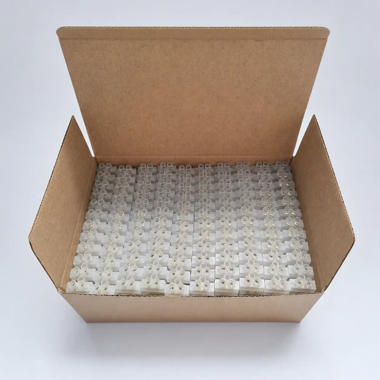
Check the product, accessories and order identity
A mixed terminal order should remain traceable from the approved model list to the packaged goods. Dimensions, connection structure, accessories, labels and quantities should match the confirmed requirement.
Screw terminal block questions
Initial answers for engineers, panel builders, equipment manufacturers, distributors and project buyers.
What information is needed to select a screw terminal block?
Provide the conductor type and cross-section, current, voltage, circuit function, number of positions, mounting method, available dimensions, required accessories, applicable standard, quantity and destination. A model number, photo, drawing or sample is helpful for replacement work.
What is the difference between UK or UT and TB or TBC terminal blocks?
UK and UT products are commonly used as modular DIN rail terminal blocks for organized cabinet wiring. TB and TBC products use barrier-style multi-pole structures for fixed equipment and distribution connections. Final selection depends on the exact model and installation.
How much torque should be applied to a screw terminal block?
There is no single torque value for every screw terminal block. Use the tightening torque, tool and conductor preparation specified for the exact model in its technical documentation and follow the equipment assembly procedure.
Can stranded wire be used in screw terminal blocks?
Many screw terminal models accept stranded conductors, but the permitted conductor construction, cross-section and ferrule requirement are model-specific. Confirm the wire data and selected terminal instructions before assembly.
Can screw terminal block accessories be mixed between series?
Not automatically. Bridge pitch, marker carrier, end-plate profile, cover shape and mounting interface can differ. Match each accessory to the exact terminal family and model.
How do I replace an existing screw terminal block?
Send the complete model number, clear front and side photos, dimensions, mounting information, conductor size, poles, rating, accessories and required quantity. Similar appearance alone is not enough to confirm compatibility.
Can SENTOP quote a complete terminal strip BOM?
Yes. SENTOP can review circuit terminals, protective earth positions, bridges, markers, end parts, covers, rails, mounting items, mixed quantities, labeling and packaging groups for a coordinated order.
Should I choose a screw terminal block or a spring terminal block?
Choose according to the approved connection process, conductor preparation, assembly volume, service procedure and equipment design. Screw terminals use a controlled tightening process, while spring designs use spring force and a model-specific operating method.
Can I request samples before bulk purchasing?
Sample availability depends on the selected model and project requirement. Send the model, quantity, application and evaluation purpose so SENTOP can review an appropriate sample plan.
Send your model, photo, drawing or BOM for terminal block review.
Request UK, UT, TB, TBC, X3 or X5 models, compatible accessories, replacement matching, mixed-model BOM organization or grouped supply for industrial equipment.
