
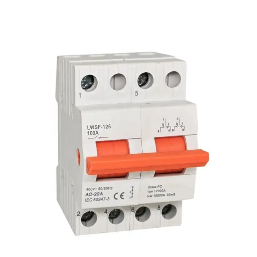
Manual Transfer Switches for Controlled Dual-Source Changeover
Choose a manual transfer switch from the actual source arrangement, system voltage, load current, poles, neutral treatment, switching duty, short-circuit coordination and installation method. SENTOP supports model matching, samples, documentation and OEM bulk supply for panel builders and electrical projects.
What does a manual transfer switch do?
A manual transfer switch (MTSE) allows a trained operator to connect a defined load to one of two approved power sources. It is used where the site can accept an operator response and a planned interruption while the source is changed.
The equipment is only one part of the transfer system. The final arrangement must also coordinate source protection, conductor routing, neutral and grounding design, enclosure, operating access and the site switching procedure.
Identify both sources and the load
Record voltage, frequency, phase, normal source, alternate source and the loads that must be transferred.
Confirm the permitted switching sequence
Define source positions, OFF or neutral position if required, and the model-specific break-before-make behavior.
Match poles, current and protection
Review switched conductors, neutral treatment, utilization duty, available fault current and protective devices.
Verify installation and operation
Confirm mounting, enclosure, handle access, terminals, labels, instructions and the qualified operator procedure.
Choose the operating method from the continuity requirement
The main decision is not the appearance of the handle or enclosure. It is who initiates the transfer, how quickly the load must recover and which monitoring or control functions the power system requires.
Manual Transfer Switch
A trained operator checks the source condition and moves the switch according to the approved procedure. Select this direction when manual response and a controlled interruption are acceptable.
Automatic Transfer Switch
A controller monitors source conditions and initiates transfer according to configured logic. Evaluate this direction for unattended sites, tighter continuity needs or generator start and retransfer control.
Selection reminder: Manual operation does not remove the need for electrical coordination. Confirm the exact product data and completed system design with qualified project personnel.
Four MTS directions for different installation needs
Use these product directions to narrow the discussion. Final availability and suitability must be confirmed from the complete model code, ratings, dimensions, switching arrangement and project requirements.
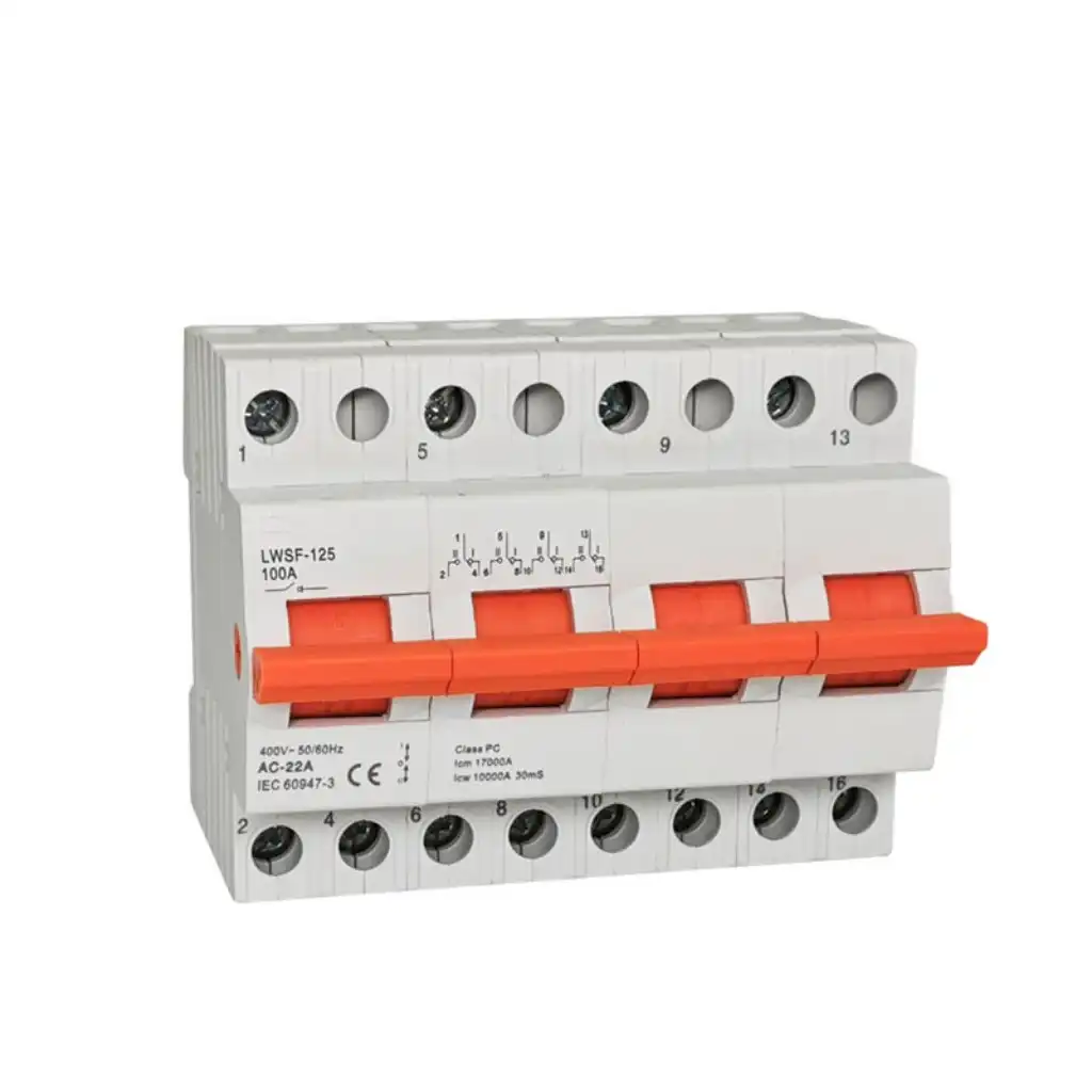
Compact Manual Changeover Switch
A compact direction for equipment panels, local source selection and space-conscious assemblies where a qualified operator makes an occasional transfer.
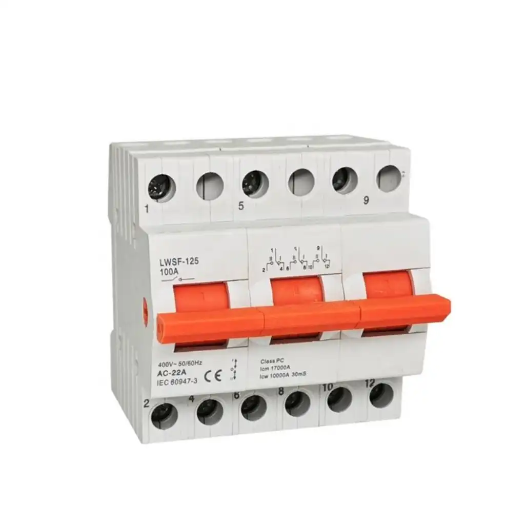
Generator Manual Transfer Switch
A manual source-changeover direction for standby generator systems where an on-site operator decides when to move the approved loads between utility and generator power.

Industrial Manual Transfer Switch
A project direction for commercial and industrial boards where switching duty, source protection, cable arrangement, handle access and operating procedure must be reviewed together.
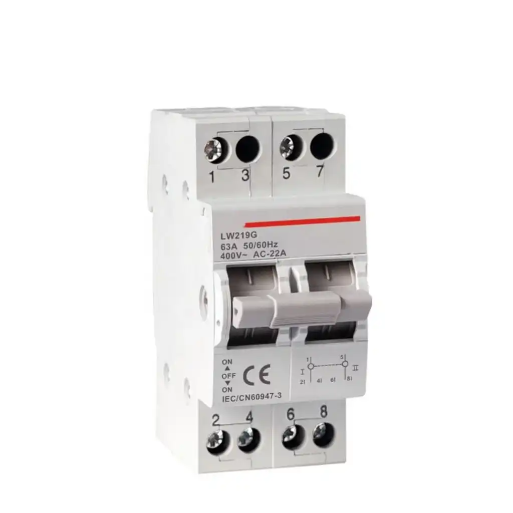
Configured MTS for Electrical Assemblies
A repeat-supply direction for panel builders and OEM projects that need controlled model identification, drawings, labels, packaging and batch documentation.
Confirm these requirements before choosing an MTS model
A useful inquiry describes the complete power system, not only an ampere value. These nine questions reduce model revisions and expose missing neutral, protection, mounting or operating requirements.
Source arrangement
Identify utility-to-generator, utility-to-utility, maintenance supply or another approved two-source arrangement.
Provide the single-line diagramVoltage and frequency
State voltage, frequency, phase sequence and whether both sources have the same electrical characteristics.
Confirm both sourcesCurrent and load duty
Provide design current and load type, including motors, transformers, UPS, lighting or mixed distribution loads.
Review utilization dutyPoles and neutral
Confirm 2P, 3P or 4P switching and how the neutral and grounding arrangement is handled.
Do not select poles from current aloneProtection coordination
Identify upstream and downstream breakers or fuses and the available fault-current information.
Switching and protection are separate checksOperating positions
Define normal source, alternate source, OFF or neutral position need and the intended contact sequence.
Confirm the exact mechanismMounting and terminals
Provide rail, panel, base or enclosure mounting, cable direction, conductor size and service-clearance needs.
Share a panel drawing or photoEnvironment and enclosure
Describe indoor or outdoor location, temperature, dust, moisture, vibration and required enclosure protection.
State the destination countryDocuments and supply plan
List standards, certificates, drawings, labels, quantity, sample needs, packaging and delivery timing.
Confirm documents per exact modelDefine the procedure before the operator moves the handle
The site procedure must follow the exact product instructions and completed electrical design. The sequence below is a specification checklist, not a universal operating instruction.
Match the switch to the complete distribution system
Pole count, neutral treatment, switching duty and short-circuit coordination can change the required device or assembly. The project engineer should confirm the final design using the exact model information and applicable local rules.
| Design item | What must be confirmed | Why it matters | Useful project input |
|---|---|---|---|
| 2-pole configuration | Single-phase conductor arrangement and whether line and neutral are switched | Affects isolation, source bonding and conductor routing | Single-line diagram and source wiring |
| 3-pole configuration | Three switched phase conductors with the neutral managed outside the mechanism | Requires a neutral and grounding design that permits a solid neutral | Grounding and bonding diagram |
| 4-pole configuration | Three phase conductors plus a switched neutral | May be required by the source and grounding arrangement | Generator bonding and neutral design |
| Rated current | Design load, load type, temperature, enclosure and conductor conditions | Frame marking alone does not prove suitability for every duty | Load schedule and design current |
| Utilization duty | Type of load and the make, carry and break duties required by the application | Different loads impose different switching stresses | Motor, transformer and mixed-load details |
| Short-circuit coordination | Available fault current, device capability and coordinated protective devices | The transfer switch and protection must operate as one system | Fault study and breaker or fuse models |
| Operating positions | Source I, source II, OFF or neutral position and the contact sequence | Determines source separation and the approved operating procedure | Sequence of operation |
| Standards and documents | Required market standard, certificates, drawings, instructions and test records | Ratings and documentation can vary by exact model and destination | Specification and approval list |
Technical references: UL Solutions lists nonautomatic transfer switches within its UL 1008 evaluation scope. Schneider Electric also uses MTSE for manually controlled source-changeover equipment. Always confirm the standard, edition and ratings on the exact proposed model.
Define the MTS from the operating responsibility
The same manual changeover principle can serve very different installations. The load, environment, source design and operating procedure determine which direction is appropriate.
Generator backup panels
Transfer approved circuits between utility and standby generator power when an operator is available.
Review generator bonding, neutral and protectionIndustrial maintenance supply
Select an alternate or maintenance source for machinery, distribution boards or service procedures.
Review isolation, interlocking and operating accessCommercial distribution
Provide controlled source changeover for selected building loads that can accept manual response time.
Review load priority and qualified operator availabilityTemporary and portable power
Connect an approved temporary source through a defined switching and connection arrangement.
Review connectors, enclosure, cables and site procedureRemote or low-complexity sites
Use a simple operator-controlled arrangement where automatic monitoring is unnecessary.
Review response time, access and environmental conditionsOEM electrical equipment
Integrate a confirmed manual changeover device into repeatable panel or machine production.
Review drawings, labels, item codes and batch documentsSend the system details for an accurate quotation
Provide the available information even if the MTS model is unknown. A single-line diagram, product photo, nameplate or panel drawing can shorten model review.
Describe both sources and the load
Voltage, frequency, phase, normal and alternate source, design current, load type and fault-current information.
Define switching and installation
Poles, neutral, positions, contact sequence, mounting, enclosure, handle access, terminals and cable direction.
Confirm supply details
Quantity, destination, standards, documents, OEM labels, packaging, sample needs and delivery schedule.
Keep every MTS order aligned with the approved specification
The quotation, drawing, product label, switching positions, accessories and shipment identification should describe the same approved model and project requirements.
Continue planning the complete changeover system
MTS selection questions
Use these answers to prepare the system information before requesting a model or quotation.
What is a manual transfer switch?
A manual transfer switch is operator-controlled equipment used to connect a defined load to one of two approved power sources. Model designs vary in poles, positions, switching duty, current rating, mounting, enclosure and protection arrangement.
When should I choose a manual transfer switch instead of an ATS?
Choose manual transfer when a trained operator can respond and the loads can accept a controlled interruption. Evaluate an ATS when unattended source monitoring, repeatable timing, generator start or remote interfaces are required.
Can a manual transfer switch be used with a generator?
It can be used in a generator application when the utility and generator voltage, frequency, phase, neutral and grounding design, protection, poles, load duty and operating procedure are suitable for the exact model.
How do I select 2P, 3P or 4P?
Select pole count from the conductors that must be switched and the system neutral and grounding design. Do not choose the pole configuration from rated current alone.
Does every MTS have an OFF or neutral position?
No. Available operating positions and contact sequences vary by mechanism. Confirm source I, source II, OFF or neutral requirements and the exact model diagram before ordering.
Does an MTS include overcurrent protection?
Not necessarily. Some products are transfer switching devices, while some assemblies use integrated or coordinated breakers. Verify the exact construction, ratings and protective-device arrangement.
What is break-before-make changeover?
Break-before-make means the load is disconnected from one source before connection to the other source. Confirm the actual sequence and operating positions from the exact model information.
What information should I send for an MTS replacement?
Send the complete model and nameplate, front and rear photos, wiring diagram, voltage, frequency, current, poles, dimensions, mounting, terminals, operating positions, protection, load type and quantity.
Can SENTOP support OEM manual transfer switch projects?
SENTOP can review recurring requirements for model configuration, labels, drawings, packaging, product identification and batch supply. Confirm technical, certification, sample and delivery requirements before release.
Send your MTS model, single-line diagram or project specification
SENTOP can review compact, generator, industrial and OEM manual transfer switch requirements for model matching, samples, electrical panels and bulk orders.
