
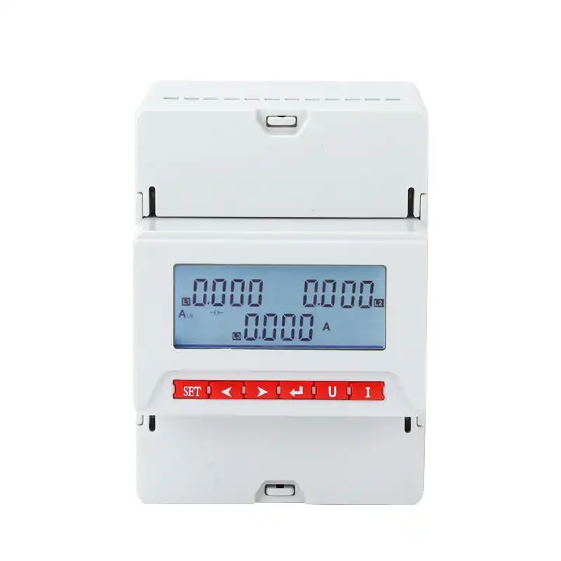
Digital Panel Meters for Electrical Panels and Power Monitoring
Select a SENTOP digital panel meter by measurement task, electrical system, input method, CT or VT ratio, display, panel cutout, auxiliary supply, accuracy requirement, communication and output needs. Product functions vary by series, so the exact model and wiring data should be confirmed before ordering.
What is a digital panel meter?
A digital panel meter is a panel-mounted instrument that receives an electrical measurement input, processes it and presents the result on a numeric or graphical display. Depending on the exact model, it may show one quantity such as voltage or current, several three-phase values, or a wider group of power and energy parameters.
The correct meter starts with the signal and system. Define what must be measured, how the signal reaches the meter, how the reading will be used and how the unit fits the panel before comparing display style or price.
Measure the electrical system
Voltage circuits, current transformers, voltage transformers or DC shunts provide the input.
Scale the input correctly
The meter configuration must match primary and secondary values, wiring type and measured range.
Process the selected quantities
The exact model determines which voltage, current, power, frequency, energy or other values are calculated.
Display or transmit the result
Operators can read the front display, while supported models may send values or status to another system.
Verify against the system
Commissioning checks ratios, phase mapping, polarity, communication and readings under known conditions.
Start with the monitoring task
Answer three questions to narrow the SENTOP meter family for review. This tool provides a planning direction only; it does not confirm the final model, accuracy, input range or communication map.
Choose the meter family by measurement objective
These six models represent selection directions from the existing SENTOP range. Confirm the exact suffix, input, display, cutout, auxiliary supply, accuracy, communication and output configuration before ordering.
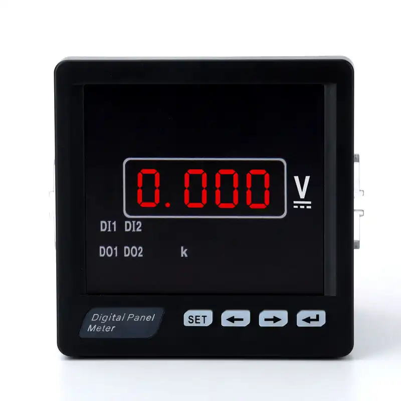
RM-DV31 Intelligent Digital Panel Meter
A compact front-panel direction for projects that need a clearly displayed electrical value and configurable measurement scaling.
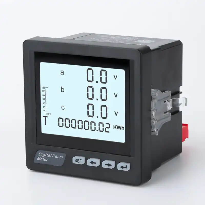
RM-3AA3Y Three-Phase Digital Ammeter
A multi-line display direction for viewing three-phase current in distribution panels and equipment cabinets.
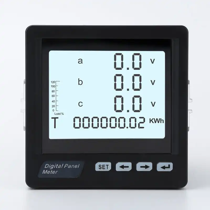
RM-3D3Y Three-Phase Multifunction Meter
A broader monitoring direction for projects that need several electrical quantities from one panel instrument rather than separate single-function meters.
RS485 LCD Digital Panel Meter
A graphical-display direction for projects that need local readings plus supported serial communication to a PLC, gateway or monitoring platform.
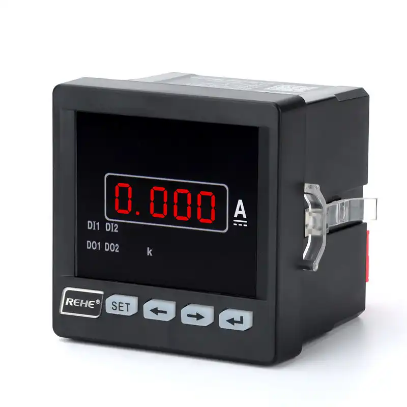
RN-DA31 LED DC Digital Ammeter
A DC current indication direction for control power, battery, charging, rectifier and other approved DC monitoring circuits.
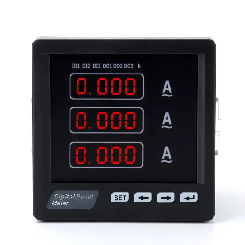
RM-3AA33 Digital Ammeter
A current-monitoring direction for buyers who need the accuracy class, display response and input arrangement documented for the exact model.
Define how each signal reaches the meter terminals
A display can look correct while the engineering value is wrong if the wiring system, transformer ratio or phase mapping is incorrect. Build the meter specification from the single-line diagram and instrument circuit.
| Input decision | What the buyer provides | What the meter review confirms | Commissioning evidence |
|---|---|---|---|
| Voltage input | System voltage, phase-to-phase or phase-to-neutral measurement and whether a VT/PT is used. | Direct input range, VT/PT secondary, ratio setting, fuse requirement and terminal assignment. | Measured voltage compared with a suitable reference instrument. |
| AC current input | Primary current, CT secondary, CT ratio, phase assignment and installation direction. | Compatible current input, programmable ratio, burden and terminal arrangement. | Phase current and direction checked under a known operating condition. |
| DC current input | Current range, shunt rating and signal, polarity and wiring distance. | Direct or shunt input, scaling, isolation, polarity indication and terminals. | Displayed value compared at known current points. |
| Electrical system type | Single phase, three-phase 3-wire, three-phase 4-wire or another supported arrangement. | Available wiring modes and which voltage and current channels are measured. | Phase mapping, totals and power-factor direction reviewed. |
| Auxiliary supply | Available AC or DC control voltage and permitted supply source. | Exact supply range, terminals, consumption, isolation and protection requirement. | Supply voltage verified before energizing the instrument. |
| Signal isolation | Grounding, common points, connected PLC or gateway and expected surge or noise environment. | Model-specific isolation, dielectric and EMC information where required. | Stable readings and communication under representative panel operation. |
Safety boundary: instrument transformers and energized panel wiring must be designed, installed and tested by qualified personnel using the meter, CT/VT and project instructions. Do not alter CT secondary circuits or panel wiring while energized unless an approved procedure and suitable equipment are in place.
Specify only the values the application will use
A single-function meter gives a direct local reading. A multifunction meter can reduce the number of instruments, but it also requires a clearer parameter, wiring and communication specification.
Voltage monitoring
Define AC or DC, phase relationship, direct or transformer input, nominal range and displayed engineering units.
Confirm the exact voltage channelCurrent monitoring
Define AC or DC, direct input, CT or shunt, primary and secondary values, polarity and required phase display.
Confirm scaling and sensor compatibilityPower quantities
List required active, reactive or apparent power, total and per-phase values and expected import or export direction.
Confirm the supported parameter listPower factor and frequency
State whether the value is needed for local indication, alarms, commissioning or continuous system monitoring.
Confirm convention, range and updateEnergy and demand
Define active or reactive energy, import or export, demand interval, reset requirements and whether data is non-billing or regulated.
Confirm function and applicable standardPower quality functions
Do not assume harmonics, events or disturbance recording from the words smart or multifunction. State each required function.
Verify model-specific capabilityMake the displayed value traceable to the measurement circuit
The meter and its external sensors form one measurement chain. Ratio, polarity, phase mapping, wiring and sensor accuracy can affect the final result even when the panel meter itself is correctly configured.
Measure the panel before choosing the front size
Front dimensions and cutout dimensions are not the same. For replacement work, also check installation depth, clamp or mounting method, terminal access and clearance for wiring.
Front bezel size
Confirm the visible width and height, display orientation and clearance from neighboring devices.
Panel opening
Measure the actual opening rather than assuming it from a nominal front-size description.
Behind-panel space
Allow for the meter body, terminals, conductor bend radius, communication plug and service access.
Panel conditions
Confirm ambient temperature, humidity, vibration, contamination and required front protection.
Send a front photo, side photo, terminal photo, complete nameplate, existing cutout, panel thickness, available depth, wiring diagram, input and supply data. Matching only the visible front dimensions can still leave incompatible terminals or electrical inputs.
Define how the reading moves beyond the front display
Local indication, serial data, alarms and retransmission are separate requirements. Specify the destination system and exact signal instead of requesting a smart meter without an interface list.
| Interface need | Buyer should define | Model review should confirm | Commissioning check |
|---|---|---|---|
| Local display only | Parameters, units, digit or screen format, viewing distance and operator actions. | Display type, pages, resolution, indicators, keys and password or setup access. | Values and units are clear under normal panel conditions. |
| RS485 serial data | Master or client system, protocol, network topology, baud rate, parity and addressing plan. | RS485 hardware, supported protocol, register map, configurable address and data format. | Correct wiring, unique address, common serial settings and valid register readings. |
| Relay or alarm output | Alarm condition, setpoint, delay, reset behavior and what the contact controls. | Number and type of outputs, logic, contact rating and isolation. | Alarm operates safely at test values and the external circuit is suitable. |
| Analog retransmission | Required signal, scaling, receiving device and isolation requirement. | Supported output type, programmable range, load capability, accuracy and terminals. | Output is checked at more than one known measurement point. |
| Digital inputs or pulse outputs | Purpose, contact type, pulse value, debounce or timing and connected equipment. | Available input/output channels and exact programmable functions. | Every point is mapped, labeled and functionally tested. |
For RS485 Modbus RTU networks, wiring and communication settings must be coordinated across all devices. Confirm the exact register map and firmware for the ordered model instead of reusing a map from another series.
Read the accuracy statement in its complete context
Accuracy class, resolution and display digits describe different things. The complete measurement result can also be influenced by CTs, VTs, shunts, wiring, configuration and operating conditions.
Confirm the measured function and range
An accuracy statement should identify the quantity, range, reference conditions and applicable model. One class should not be assumed for every displayed parameter.
Include CT, VT and shunt performance
The panel meter displays the signal it receives. Sensor ratio error, phase error, wiring and incorrect configuration can affect system-level results.
IEC 61557-12 specifies requirements for power metering and monitoring devices within electrical distribution systems. Electricity meters used for regulated or billing purposes can fall under different IEC 62053 requirements. Confirm the intended use, destination-market rules and exact model evidence; this category page does not establish revenue-metering suitability.
Choose the panel meter from the decision it supports
Applications help define the measurement task, but the single-line diagram and signal details still determine the exact input and model.
Low-voltage distribution panels
Display feeder or incomer voltage, current and selected power-system quantities for local operation and maintenance.
Review system type, CT/VT ratios and cutoutMotor control and machinery
Monitor motor current, control supply or selected operating values while accounting for starting current and electrical noise.
Review range, sensor, update behavior and EMC environmentGenerator and ATS panels
Provide source and load indication alongside transfer controls without assuming the meter performs protection or source switching.
Review both sources, frequency and communicationDC control and battery systems
Indicate DC current through a compatible direct input or shunt arrangement in approved control, charging or rectifier circuits.
Review polarity, shunt data, isolation and supplyEnergy monitoring systems
Send supported values to a PLC, gateway or monitoring platform for operational visibility and non-billing analysis.
Review protocol, register map, ratios and data purposeOEM electrical equipment
Integrate an approved meter model, cutout, wiring, settings and labels into repeatable equipment production.
Review BOM identity, drawing revision and change controlSend the signal, panel and data requirements
A useful quotation identifies what is measured, how it is wired, where the meter fits and how the reading will be used. For replacements, photos and existing model information are especially important.
Define the measurement
AC or DC, single or three phase, required quantities, expected range, CT, VT or shunt data and accuracy requirement.
Define the panel integration
Front size, cutout, available depth, auxiliary supply, terminal access, environment and replacement photos if applicable.
Define data and supply scope
RS485, protocol, register map, alarms, outputs, quantity, destination, standards, documents, labels and packaging.
Approve the display, wiring and configuration together
A sample can confirm more than appearance. Use it to review the exact item code, terminals, menus, ratios, communication and fit before a larger or repeating order.
Continue from product selection to correct application
Questions to answer before selecting a meter
Use these answers to prepare a model review. Final values and functions must be checked against the exact SENTOP datasheet and project wiring.
How do I choose a digital panel meter?
Start with the required measurement, AC or DC system, single or three phase, input range and whether the signal is direct, CT, VT or shunt based. Then confirm cutout, depth, supply, accuracy, display, communication, outputs, environment and documents.
What is the difference between a single-function and multifunction meter?
A single-function meter focuses on one quantity such as voltage or current. A multifunction meter can calculate and display several power-system quantities from coordinated voltage and current inputs. Confirm the exact parameter list for the selected model.
Can a digital panel meter measure current directly?
It depends on the current range and exact input. Many AC panel meters use a compatible current transformer, while DC meters may use a direct input or external shunt. Match the primary and secondary signal to the meter terminals and configuration.
How do I select the CT ratio for a digital ammeter?
Select the CT primary rating from the circuit and expected current, then confirm the CT secondary matches the meter input. Enter the approved ratio in the meter and verify phase orientation, polarity, burden and displayed values during commissioning.
What is the difference between front size and panel cutout?
The front size is the visible bezel dimension. The cutout is the opening required in the panel and is usually smaller. Also confirm body depth, panel thickness, mounting method, terminals and wiring clearance.
Do all SENTOP digital panel meters support RS485 Modbus?
No universal communication feature should be assumed across the entire range. Confirm RS485 hardware, protocol, register map, address range, baud rate, parity, terminals and firmware for the exact model code.
What settings are needed for RS485 communication?
Typical serial-network settings include protocol, device address, baud rate, parity and stop bits. All devices on the bus must use compatible communication settings, and the master system must use the correct model-specific register map.
Does a higher display resolution mean higher accuracy?
Not necessarily. Resolution describes the smallest displayed or processed step, while accuracy describes closeness to the specified value under stated conditions. Review accuracy class, range, reference conditions and the complete CT, VT or shunt measurement chain.
Can a panel meter be used for billing energy?
Only when the exact meter, installation and approval scope meet the applicable revenue or billing requirements. A general power-monitoring function or displayed energy value does not by itself establish regulated billing suitability.
What information should I send for a replacement meter?
Send the complete nameplate, front, side and terminal photos, cutout, available depth, wiring diagram, measured signal, CT/VT or shunt data, auxiliary supply, communication, outputs and required accuracy.
What should be included in a digital panel meter RFQ?
Include the measurement list, system type, AC or DC values, input ranges, transformer or shunt ratios, panel dimensions, auxiliary supply, accuracy, display, communication, outputs, quantity, destination, standards and required documents.
Send your wiring diagram, meter model or panel requirement
SENTOP can review the meter direction from the electrical system, signal input, panel cutout, communication needs and project quantity before confirming an exact quotation.
