

Electrical Calculators turn project data into clearer decisions
Calculate load current, power conversion, power factor, voltage drop, transformer fault current, CT ratio, transfer-switch load and terminal-strip length. Use the results to prepare a better technical enquiry, then verify the final design against project standards and exact equipment data.
Calculate first. Verify before selection.
A useful calculator makes the assumptions visible. It does not replace the one-line diagram, conductor data, installation method, protection coordination or equipment documentation.
Results on this page are planning values for qualified technical review, not installation instructions.Choose the system
Distinguish DC, single-phase AC and balanced three-phase AC. For three-phase calculations, enter line-to-line voltage unless the tool states otherwise.
Use real operating data
Prefer nameplate values, measured current, actual power factor, cable resistance, transformer impedance and verified equipment ratings.
Read the assumptions
Each result states what has been included and what still needs engineering review. Harmonics, inrush, temperature and coordination can change the final selection.
Keep a project record
Every calculated result can be added to the worksheet below so purchasing and engineering can review the same input assumptions.
Convert the basic electrical values that define a load requirement
Use these calculators to establish working current, real power, apparent power and reactive-power values before discussing meters, transfer switches, breakers or auxiliary power products.
AC results assume sinusoidal values and, for three-phase calculations, a balanced load.
Power, Current & Voltage Calculator
Calculate current from real power or real power from current for DC, single-phase AC or balanced three-phase AC.
Check next: motor starting current, harmonics, duty cycle, load diversity and the exact equipment rating.
Schneider Electric formula referencekW, kVA & HP Converter
Relate electrical input power, apparent power and estimated motor output horsepower.
Interpretation: HP is estimated mechanical output using the entered efficiency. Always use motor nameplate and manufacturer data for selection.
Power Factor & kVAr Calculator
Estimate present reactive power and the compensation difference between two power-factor values.
Do not select capacitor banks from this value alone. Harmonics, switching steps, resonance and utility rules require qualified review.
Fluke power factor referenceEstimate the values that begin a wiring and protection review
These tools calculate voltage drop from entered conductor impedance, establish an ampacity baseline and estimate transformer-terminal fault current. They do not choose a final cable or breaker.
Final conductor and protective-device selection depends on installation method, temperature, grouping, fault level and the applicable project rules.
Voltage Drop Calculator
Estimate balanced circuit voltage drop using one-way length and conductor resistance and reactance in ohms per kilometre.
Check next: conductor temperature, parallel conductors, harmonic current, load distribution, starting conditions and the permitted project voltage drop.
IEC 60364-5-52 wiring referenceCable & Breaker Review Current
Calculate load current and apply a visible design factor before detailed conductor and protection coordination.
No cable size or breaker rating is selected here. Verify ampacity, installation method, protective characteristics, breaking capacity, selectivity and load inrush.
Short-Circuit Current Estimate
Estimate symmetrical fault current at transformer terminals from transformer kVA, voltage and percentage impedance.
Limited estimate only. Utility contribution, cable impedance, motor contribution, voltage factor and fault type are excluded. Use a complete study for protection and equipment duties.
IEC 60909-0:2026 calculation scopeOrganize the inputs needed for metering, transfer and panel products
These tools turn early project quantities into a technical starting point. Exact CTs, transfer switches, terminal systems and SPDs still require model and application review.
Use equipment ratings and project drawings wherever available. Do not change energized CT circuits or panel wiring from a calculator result.
CT Ratio Calculator
Calculate a primary-rating starting value and the expected secondary current at maximum operating load.
Check before selection: available standard ratio, meter input, accuracy class, burden, conductor or busbar size, window and frequency.
Schneider Electric CT selection inputsTransfer Switch Load Calculator
Calculate diversified load current and an adjustable planning current for a transfer-switch enquiry.
This is not a transfer-switch rating. Verify utilization category, source and load fault data, inrush, neutral treatment, transition method and coordination.
IEC 60947-6-1:2026 scopeTerminal Strip & Rail Length Planner
Estimate terminal positions, spare terminals and occupied DIN rail length from an average product width.
Physical estimate only. Verify exact widths, end plates, barriers, bridges, marker carriers, rail clearances, duct access and mixed terminal families.
Surge Protection Starting Point
Generate the application questions needed before selecting and coordinating a surge protective device.
Begin with distribution-level surge protection and confirm coordination with upstream and downstream SPDs.
No SPD type or rating is selected automatically. Confirm required protection, impulse exposure, system voltage, earthing arrangement, short-circuit data, backup protection and coordination.
IEC 61643-12 selection principles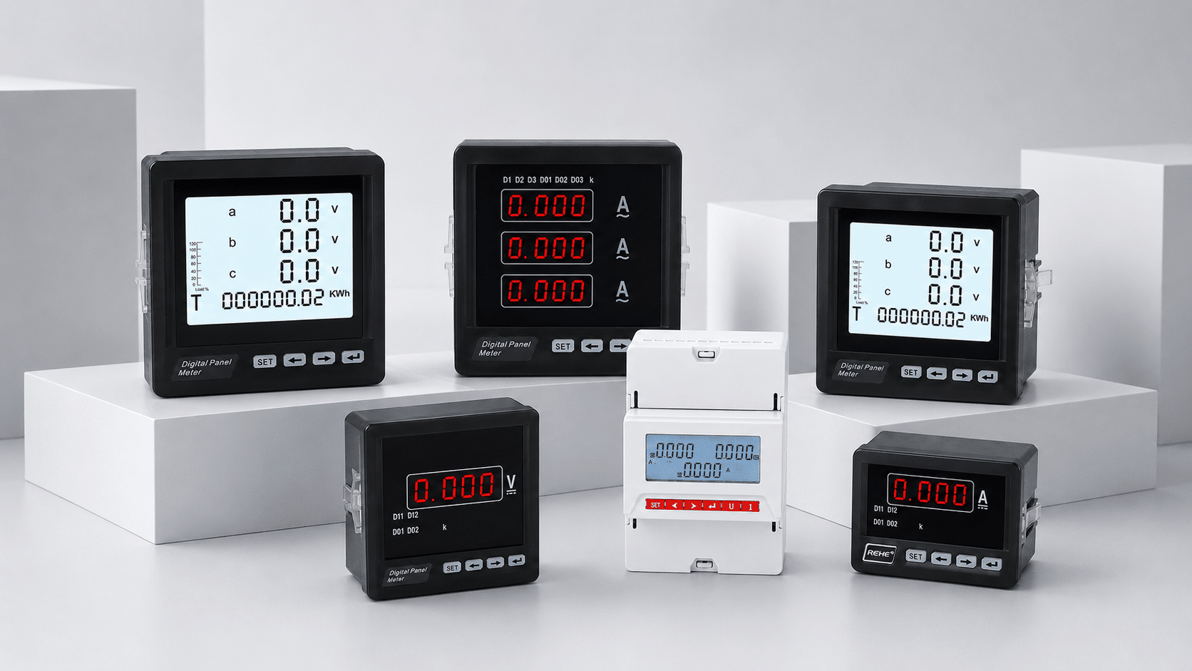
Know what the calculator has not included
The result is useful only when its assumptions match the real system. Review these four areas before turning a number into a purchase specification.
Keep your calculated values in one technical summary
Run any calculator above and the latest result will be added here. Copy the summary for your RFQ, or open the technical-review popup and add the one-line diagram, model reference and destination.
- Run a calculator to build your project summary.
Use the result to prepare a specific product requirement
The calculations become most useful when they are paired with the application, drawing and exact product function.
Transfer Switching
Send load current, voltage, phases, poles, source data, operating method and required transition behaviour.
Explore transfer switchesPanel Measurement
Send measured quantities, input range, CT or shunt data, auxiliary supply, cutout and communication needs.
Explore digital panel metersTerminal Systems
Send conductor data, circuit functions, terminal count, rail space, markers, bridges and accessory requirements.
Explore terminal blocksQuestions before using a calculated value
These answers clarify the assumptions and the point where a qualified designer or exact product document is needed.
Can I use these results to order a cable or circuit breaker?
No. The tools provide load current, an adjustable ampacity baseline and preliminary voltage-drop or fault-current values. Final cable and protective-device selection must consider the applicable rules, installation method, temperature, grouping, conductor withstand, trip characteristics, breaking capacity and coordination.
Which voltage should I enter for a three-phase calculation?
Enter line-to-line voltage for the balanced three-phase formulas on this page. If your available data is phase-to-neutral voltage, convert or verify the system definition before calculating.
Why does the motor calculation include efficiency?
Mechanical output power and electrical input power are different. Efficiency is included when estimating motor input or output conversion. Use the motor nameplate and manufacturer data for an actual motor selection.
Does the voltage-drop calculator choose a conductor size?
No. It uses the resistance and reactance entered by the user. Obtain those values for the proposed conductor and operating temperature, then verify ampacity and all installation requirements separately.
Is the transformer short-circuit estimate suitable for breaker selection?
Not by itself. It estimates current at transformer terminals from kVA and percentage impedance. A complete study may need utility contribution, cable and busbar impedance, motors, generators, voltage factors and different fault types.
How should I choose a current-transformer ratio?
Start from the expected maximum primary current and the meter's accepted secondary input, then verify the nearest suitable manufactured ratio, accuracy class, burden, frequency, conductor or busbar size and window dimensions.
Can the transfer-switch calculator select an ATS model?
No. It calculates a planning current and records the operating method and poles. The final model must match utilization category, source and load data, neutral arrangement, short-circuit duty, transition method, controller and project requirements.
Why does the surge-protection tool produce a checklist instead of a rating?
SPD selection depends on installation location, lightning exposure, earthing system, system voltage, short-circuit conditions, backup protection, required protection level and coordination with other SPDs. A short questionnaire cannot safely determine all of these values.
Have a calculation, one-line diagram or product model to review?
Send the worksheet together with system voltage, load data, destination, quantity and the product function you need. SENTOP will help organize the next product-matching step.
