

Generator & Standby Systems for Controlled Power Continuity
Plan the utility-to-generator transfer path around prioritized loads, source conditions and the required operating sequence. SENTOP supports transfer switching, panel wiring, measurement and selected low-voltage components for clearly defined standby projects.
Define what the standby system must preserve
A transfer switch cannot correct an undersized generator, unclear load list, incompatible neutral arrangement or incomplete control sequence. Make the system decisions first, then match the switching and panel components.
Separate the loads by consequence
Identify what must remain powered, what can restart later and what should stay disconnected while the generator is carrying the standby load.
Define the interruption and timing
Record acceptable outage, generator start delay, source acceptance time, transfer delay, retransfer delay and engine cool-down requirement.
Confirm both source characteristics
Utility and generator voltage, frequency, phases, earthing, fault contribution and generator transient performance affect the complete design.
Write the operating sequence
Define sensing, start command, source availability, interlocking, transfer, return-to-normal behavior, manual modes and alarm handling.
Plan control and power connections
Separate source sensing, generator start contacts, auxiliary feedback, power conductors, neutral, PE and remote communication wiring.
Keep settings and revisions traceable
Record the approved model, controller settings, wiring diagram, test expectations, labels and project revision for commissioning and repeat orders.
Treat the transfer switch as one part of the complete standby chain
This simplified path helps buyers identify the information and panel components around a typical utility-generator arrangement. The responsible designer must adapt it to the actual project.
Size and control the system from the loads that will actually transfer
Names and priorities vary by project. The purpose of grouping is to prevent every connected load from being treated as equally urgent or starting at the same moment.
Loads that must be restored first
Functions whose loss creates the highest operational, safety or process consequence according to the responsible project authority.
Loads that support continued operation
Loads that may reconnect after the generator has stabilized or after the first essential group is supplied.
Loads that can remain off during standby
Nonessential or high-demand loads that can be isolated, shed or restored only after normal utility power returns.
Select the operating method from system behavior
Use these project directions to clarify the application before requesting an exact transfer-switch model.
Automatic utility-to-generator transfer
For systems that must detect a normal-source problem, command generator start and transfer without waiting for an operator.
Standby restoration must occur automatically and generator start, source acceptance, transfer, retransfer and cool-down are defined.
System voltage/frequency, rated current, poles, neutral, source sensing, timing, start contact, interlocking, auxiliary signals and short-circuit data.
Automatic transfer switch with generator-oriented control and documented source sequence.
Operator-controlled manual changeover
For systems where a trained operator can verify source readiness and the load can accept a planned interruption.
Automatic restoration is not required and an operator can follow a documented switching and generator-start procedure.
Source arrangement, poles, neutral, rated current, utilization duty, handle access, interlocking, enclosure and operating procedure.
Manual transfer switch with clear source positions and switching arrangement for the intended circuit.
Dedicated essential-load standby panel
For projects that separate the loads requiring generator support from the wider normal distribution system.
Only selected circuits should transfer, reducing generator demand and making load priorities easier to document.
Essential circuit list, diversity, starting sequence, feeder protection, distribution arrangement, enclosure, metering and spare capacity.
Transfer switch, selected protection/distribution products, panel meters, terminal blocks and auxiliary wiring components.
Multiple-source, redundant or critical standby systems
For projects involving several generators, bus sections, bypass arrangements, synchronization, parallel operation or specialized critical-service rules.
These systems require a complete power-system architecture, protection study, operating philosophy, control logic and project-specific compliance plan.
All source and bus data, fault levels, generator controls, synchronization, interlocking, redundancy, bypass, communications and testing responsibilities.
Component or documented BOM discussion only where the required product duty and system responsibility are clearly defined.
Write the operating sequence before fixing controller settings
The following is a common conceptual sequence, not a universal commissioning procedure. Each project must define thresholds, delays, permissives and failure responses.
Monitor Normal Source
Controller evaluates source voltage, frequency and phase conditions.
Confirm Source Failure
A delay helps distinguish a real outage from a short disturbance.
Start Generator
Dry contact or defined interface commands the generator controller.
Accept Standby Source
Generator voltage and frequency must enter the approved window.
Transfer the Load
Interlocked switching connects the selected load to standby power.
Return to Normal
After utility stability and retransfer delay, the load returns.
Cool Down & Stop
Generator runs unloaded for the defined period before stopping.
Components around the generator transfer panel
Transfer switches are central to this application. Terminal systems and panel meters support the control, sensing, distribution and service requirements around the switching equipment.
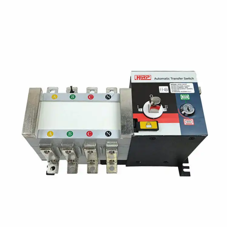
Automatic & Manual Transfer Switches
Choose the operating method first, then confirm the exact system, poles, current, neutral treatment, source sensing, timing, generator-start interface, installation and short-circuit conditions.
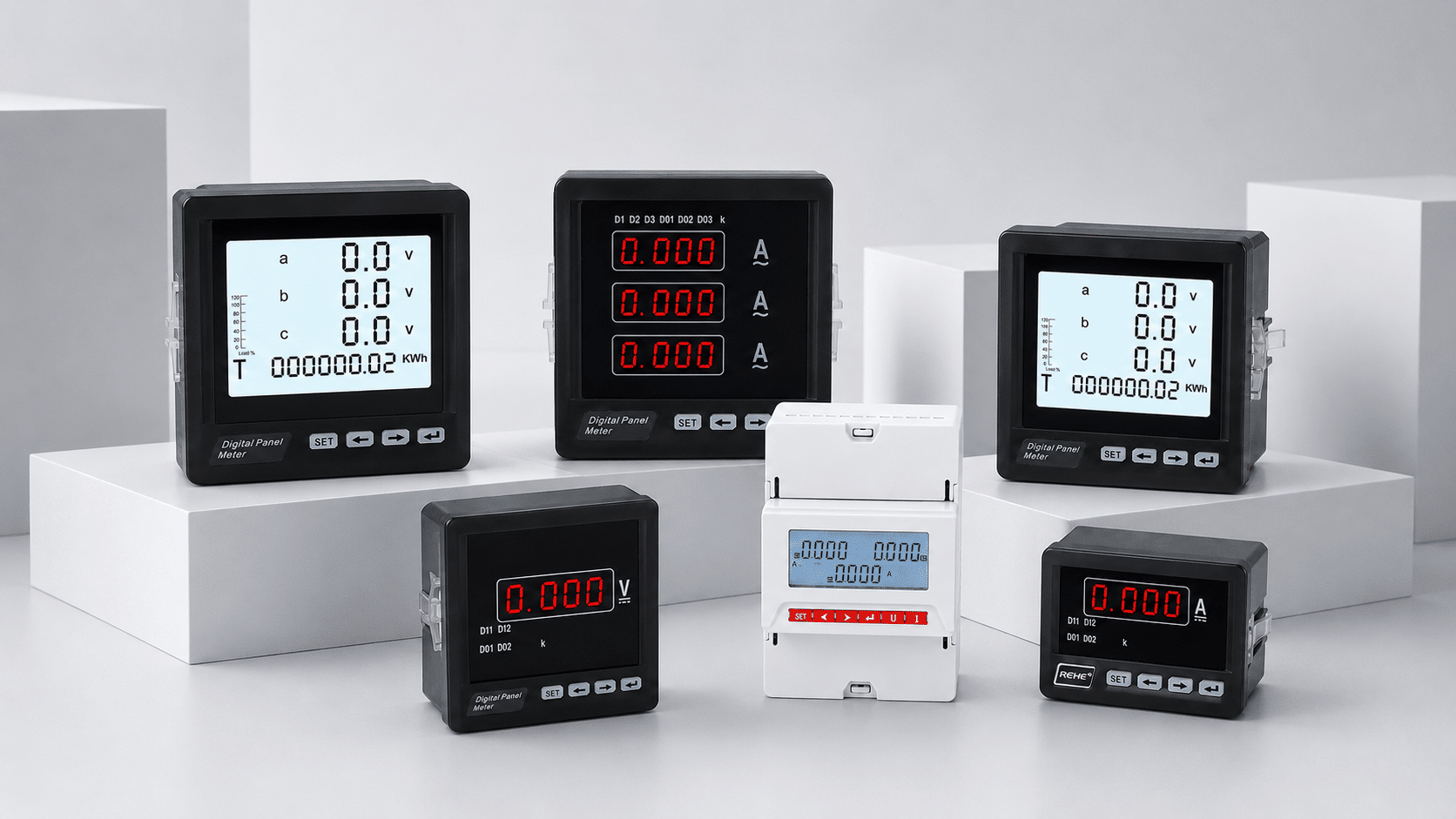
Digital Panel Meters
Local voltage, current, frequency, power and energy indication, with selected communication directions.
Explore panel meters →
Terminal Blocks & Accessories
Organized interfaces for source sensing, start contacts, feedback, alarms, PE and distribution wiring.
Explore terminal systems →Protection, control power and distribution
Send the system data—not only an ATS ampere rating
A single-line diagram is ideal. If it is not available, use this checklist to organize a useful first review.
| Data group | Provide when available | Why it matters | Responsible confirmation |
|---|---|---|---|
| Load profile | Essential/operational/deferred loads, running kW/kVA, power factor, motor starting, nonlinear loads and staged connection | Controls generator demand, transfer current, sequencing and load-shedding needs | Power-system and generator designer |
| Normal source | Voltage, phases, frequency, neutral/earthing, fault level, upstream protection and phase sequence | Controls sensing, device ratings, poles and short-circuit coordination | Electrical system designer |
| Generator source | Generator rating/class, voltage/frequency, transient behavior, breaker, controller, start interface and fault contribution | Determines source acceptance, load compatibility and protection behavior | Generator manufacturer and system designer |
| Transfer equipment | Automatic/manual, poles, neutral, rated current, utilization, timing, class, interlocking, positions and mounting | Defines the exact transfer-switch duty and physical arrangement | Panel/system designer and product reviewer |
| Control & signals | Controller supply, dry contacts, generator start, auxiliary feedback, alarms, remote control and communication | Prevents interface mismatches during panel wiring and commissioning | Controls designer and generator integrator |
| Project conditions | Ambient, altitude, enclosure, target country, standards, approvals, quantity, labels, packaging and documents | Affects ratings, acceptance, configuration and supply preparation | Project authority and buyer |
Important: SENTOP supports component and BOM matching. Generator sizing, protection studies, earthing, control logic, load sequencing, functional safety, installation design and complete system verification remain with the responsible engineering parties.

Keep the approved model and operating sequence tied to the project revision
A reliable purchasing record identifies the model, electrical duty, settings, wiring interfaces, labels, accessories and documents associated with the approved system design.
Single-line diagram, source data, load list, sequence, model references and enclosure arrangement.
Ratings, poles, neutral, fault data, signals, terminal requirements, monitoring and target market.
Compare documented characteristics, physical fit, terminals, accessories and expected configuration.
Preserve model, quantity, controller or accessory details, labels, packaging, documents and revision.
Apply product standards inside the complete standby-power design
Transfer equipment and generator sets have distinct standards, while critical or safety-related applications may require additional local rules and project-specific provisions. Confirm the exact edition, model scope, destination and responsible authority.
Applies to transfer switching equipment used to transfer a load between power supply sources within its stated voltage scope.
Review the official IEC scopeDefines classifications for application, rating and performance of reciprocating-engine-driven AC generating sets and associated equipment.
Review the official ISO scopeSpecifies criteria for controlgear and switchgear associated with reciprocating-engine-driven AC generating sets.
Review the official ISO scopeAddresses generating sets used for emergency power supply to safety services; specialized applications can require additional requirements.
Review the official ISO scopeSend four information groups for a faster first review
You can begin with a single-line diagram, BOM, model reference, panel photo or written requirement. Identify what is confirmed and what remains under design.
Facility or equipment type, essential loads, acceptable interruption and operating objective.
Voltage, phases, frequency, generator rating, source protection, fault data and earthing.
Automatic/manual method, poles, neutral, start contact, timing, feedback, alarms and modes.
Quantity, destination, target market, approvals, labels, packaging and delivery timing.
Questions before selecting transfer and panel components
Answers for generator-panel builders, equipment manufacturers, electrical contractors and project buyers.
What information is needed to select a generator automatic transfer switch?
Provide utility and generator voltage/frequency, phases, rated current, poles, neutral/earthing arrangement, fault data, load types, acceptable interruption, generator start interface, timing, controller functions, mounting, enclosure and target standards.
How do I decide between an automatic and manual transfer switch?
Use automatic transfer when restoration must occur without waiting for an operator and the generator-start and transfer sequence is defined. Manual changeover may suit systems where trained operators are available and a planned interruption is acceptable.
Should all facility loads connect to the standby generator?
Not necessarily. Many projects separate essential, operational and deferred loads. The responsible designer must assess load priority, generator capacity, starting behavior, diversity and whether staged connection or load shedding is required.
Why are the number of poles and neutral arrangement important?
The source earthing and neutral arrangement affect whether the neutral is switched and how protection and bonding are coordinated. This decision must come from the complete system design, not from the transfer-switch catalogue alone.
Can SENTOP supply components around the transfer switch?
Yes. Depending on the defined BOM, the enquiry can include terminal blocks and accessories, digital panel meters and selected supporting protection, control-power and distribution products. Each model must be confirmed against its own duty.
Can a panel meter monitor both utility and generator sources?
The measurement architecture determines whether one or more meters and switching or communication interfaces are required. Confirm measured quantities, input method, CT/shunt ratios, panel cutout, auxiliary supply, outputs and communication for the exact design.
Does the ATS controller start the generator directly?
Many generator-oriented systems use a defined dry-contact or control interface between the ATS controller and generator controller. The exact electrical interface, contact logic, voltage and failure behavior must be checked for both products.
Does an approved ATS make the complete standby system compliant?
No. Product approval applies to the exact covered model and scope. Generator sizing, system protection, earthing, installation, controls, testing and complete project compliance remain separate responsibilities.
Have a single-line diagram, ATS sequence or generator-panel BOM?
Send the available source data, loads, control requirements, quantities, destination and documents. SENTOP will help organize the next component-matching step.
