
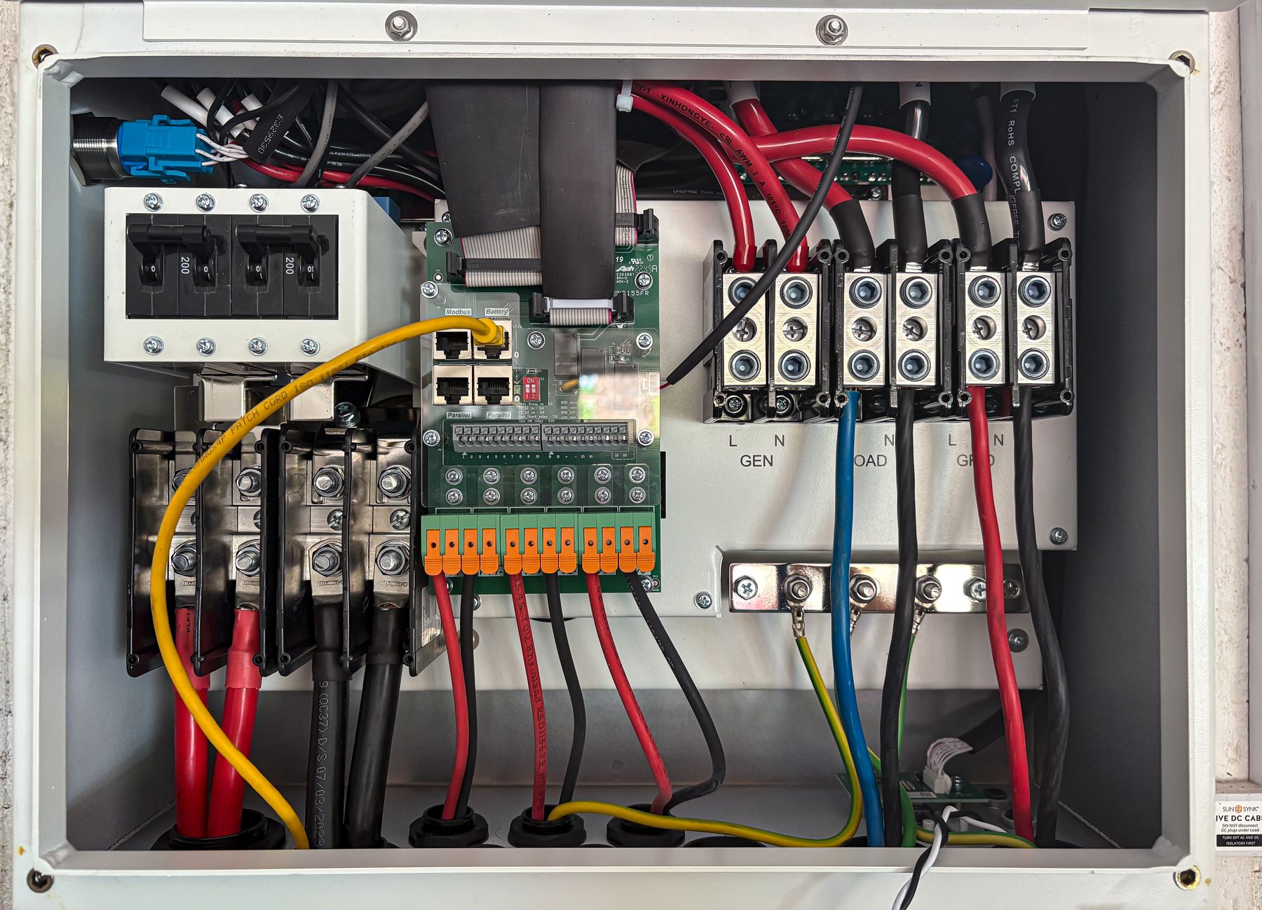
Electrical components for clearer panel BOMs and repeatable assembly
SENTOP supports panel builders, switchgear assemblers and electrical equipment manufacturers with terminal systems, transfer switches, digital panel meters and selected low-voltage products. Start with the electrical drawing, target market and installation requirements—not a generic product list.
Component supply should reduce uncertainty before assembly begins
A panel BOM is more than a list of product names. Each item must suit the circuit function, conductor, panel space, operating environment, target market and documentation requirement. SENTOP helps organize this information so the quotation and sample review begin with the correct questions.
Mechanical fit and panel space
Confirm mounting method, module width, panel cutout, DIN rail, conductor entry and accessory compatibility.
Electrical ratings matched to the duty
Review voltage, current, poles, breaking or switching duty, measured signal and application conditions by exact model.
Repeatable model and accessory control
Keep terminal accessories, labels, bridges, meters and switch configurations consistent across repeat panel builds.
Documents suitable for project review
Identify the drawings, model data, certificates, label content and packaging information needed before ordering.
Start from the circuit function, then confirm the exact model
Choose a functional zone to see which information helps SENTOP organize a useful product recommendation or quotation.
Terminal blocks and wiring organization
Build the terminal strip around conductor data, circuit function, PE positions, test requirements and the complete accessory system.
Automatic or manual source changeover
Define the power sources, transfer method and load duty before selecting the switch arrangement.
Panel measurement and monitoring
Select the meter from the quantities to display, input method, panel opening and communication requirement.
Low-voltage circuit protection
Protection devices must be selected within the complete system design and coordinated with the circuit, fault level and applicable requirements.
Control switching and auxiliary power
Organize control power and switching products around the control voltage, load duty, mounting and cabinet environment.
Three product families at the center of our panel-building support
These ranges are presented first because they match frequent panel wiring, changeover and measurement requirements. Final models are confirmed against project data.

Terminal Blocks & Wiring
Connection systems for control circuits, power distribution, protective earth, testing, disconnection and organized field wiring.
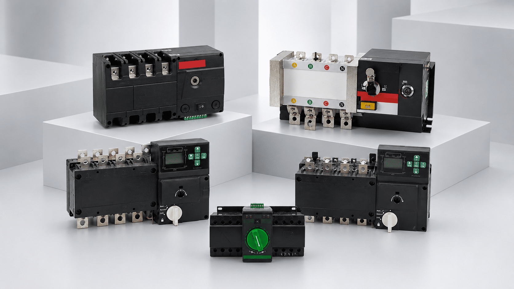
Automatic & Manual Transfer Switches
Source-changeover directions for utility, generator and standby systems where the switching method and electrical duty are clearly defined.
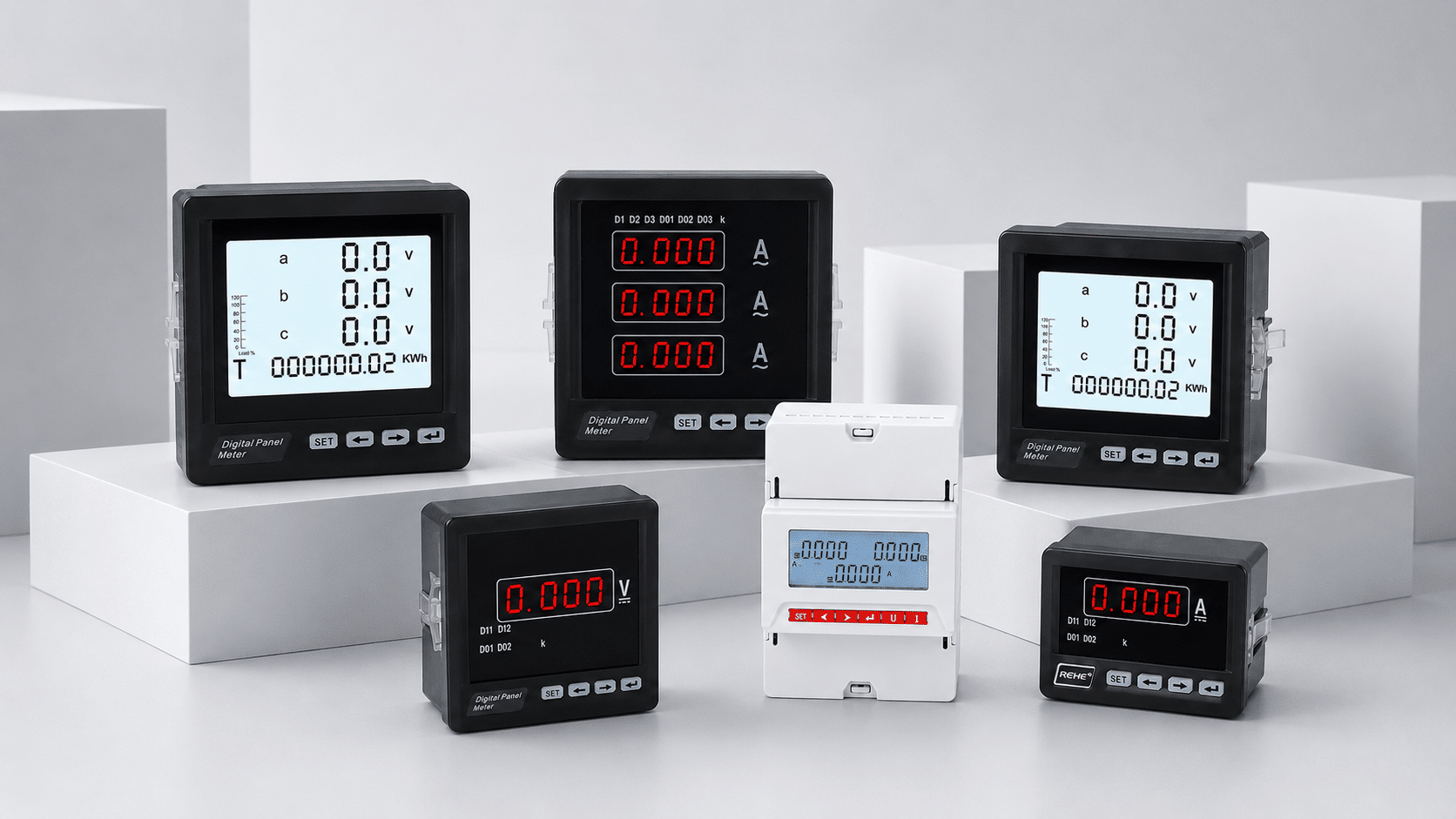
Digital Panel Meters
Panel-mounted indication and monitoring for voltage, current, frequency, power, energy and multifunction electrical data.
Low-Voltage Protection
Control & Distribution
Information that makes panel-component matching faster and more useful
Use this table to prepare an enquiry. The exact data required depends on the product family and project responsibility.
| Review area | Provide when available | Why it matters | Typical output |
|---|---|---|---|
| System and application | One-line diagram, control schematic, system voltage, frequency, phase, earthing and application | Defines the electrical context and limits incorrect product assumptions | Product-family direction and missing-data list |
| Component ratings | Current, poles, conductor range, signal input, switching or protection duty and fault data where applicable | Connects the printed model data to the actual circuit requirement | Candidate model or data comparison |
| Mechanical integration | DIN rail, panel cutout, module width, enclosure dimensions, cable entry, spacing and mounting orientation | Prevents a suitable electrical product from becoming an unsuitable mechanical fit | Dimension and installation review |
| Accessories and assembly | Bridges, markers, end plates, terminal clamps, auxiliary contacts, CTs, shunts and wiring accessories | Keeps the component system complete instead of quoting the main item alone | More complete BOM and accessory schedule |
| Market and documentation | Destination country, applicable standard, required approvals, label language, drawings and certificate expectations | Approval and documentation scope must be checked by exact model and target market | Document availability and verification plan |
| Commercial and delivery | Sample quantity, production quantity, repeat schedule, packaging, required delivery date and destination | Allows quotation, sampling and packaging to match the real purchasing stage | Commercial quotation and supply plan |
Important: SENTOP product matching supports the component-selection discussion. The panel designer or assembly manufacturer remains responsible for the complete system design, coordination, assembly verification and compliance required by the project.
From drawing review to repeatable component supply
A structured review keeps technical questions, samples, model references and purchasing details connected.
Share the panel requirement
Send the BOM, one-line diagram, model list, ratings, photos, quantities, destination and required documents.
Clarify technical gaps
Confirm the circuit function, dimensions, accessories, operating conditions and target-market expectations.
Review models and samples
Compare the available data, drawings or samples before committing the product to a production panel.
Organize the repeat order
Confirm final models, quantities, labels, packaging, documents, production schedule and delivery preparation.
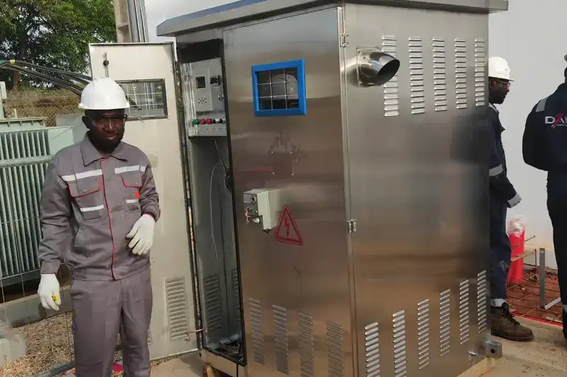
Build confidence with project data—not broad promises
Panel builders need evidence that the proposed component fits the application and can be supplied consistently. SENTOP focuses the discussion on available model information, samples, accessories, documentation, packaging and repeat-order requirements.
Component data and assembly verification are different responsibilities
Low-voltage assemblies are evaluated as systems. A component's data or approval does not by itself establish compliance of the complete panel. Confirm the applicable standard, target market, design responsibility and verification plan before finalizing the BOM.
Covers general definitions, service conditions, construction requirements, technical characteristics and verification requirements for low-voltage switchgear and controlgear assemblies.
Review the official IEC publicationDefines specific requirements for power switchgear and controlgear assemblies within its scope, including indoor and outdoor assemblies.
Review the official IEC publicationProvides product-specific requirements across multiple low-voltage switchgear and controlgear categories. The applicable part depends on the exact device and duty.
Review the official IEC seriesSend the information that controls panel-component selection
A complete drawing is helpful, but you can also begin with a BOM, model list, product photos or a requirement summary. We will identify the missing information needed for the next review step.
Questions before selecting panel components
Answers for switchgear assemblers, control-panel builders and electrical equipment manufacturers.
Can SENTOP review a complete panel BOM?
Yes. Send the BOM with available drawings, ratings, quantities, target market and required documents. SENTOP can organize product directions and identify missing selection information. The panel designer or assembly manufacturer remains responsible for the complete design and verification.
Can I request a replacement for an existing component?
Yes. Provide the full model number, label photos, dimensions, terminal arrangement, electrical data and application. A sample can be useful when markings or documents are incomplete. A replacement should be validated before production use.
Can terminal blocks and accessories be supplied as one system?
They can be reviewed together. Include terminal functions, conductor sizes, quantities, PE positions, bridges, markers, end plates, rail clamps and other accessories so the terminal strip is not quoted as isolated main components.
What information is required for a transfer switch?
Provide the source arrangement, one-line diagram, system voltage, frequency, poles, rated current, neutral treatment, automatic or manual operating requirement, installation space and target market.
How should a digital panel meter be selected?
Start with the quantities to measure, AC or DC system, input range, direct or transformer input, CT or shunt ratio, panel cutout, auxiliary supply, output and communication requirements.
Does a component certificate cover the complete switchgear assembly?
No. Component data and approvals do not by themselves establish compliance of the complete assembly. The responsible party must determine the applicable assembly standard, design rules, coordination and verification requirements.
Can SENTOP support samples and repeat orders?
Sample and repeat-order requirements can be discussed. Confirm the exact model, quantity, labels, packaging, required documents, production schedule and destination before ordering.
Have a BOM, drawing or existing model list to review?
Send the available technical data, quantities, destination and document requirements. SENTOP will help organize the next component-matching step.
