
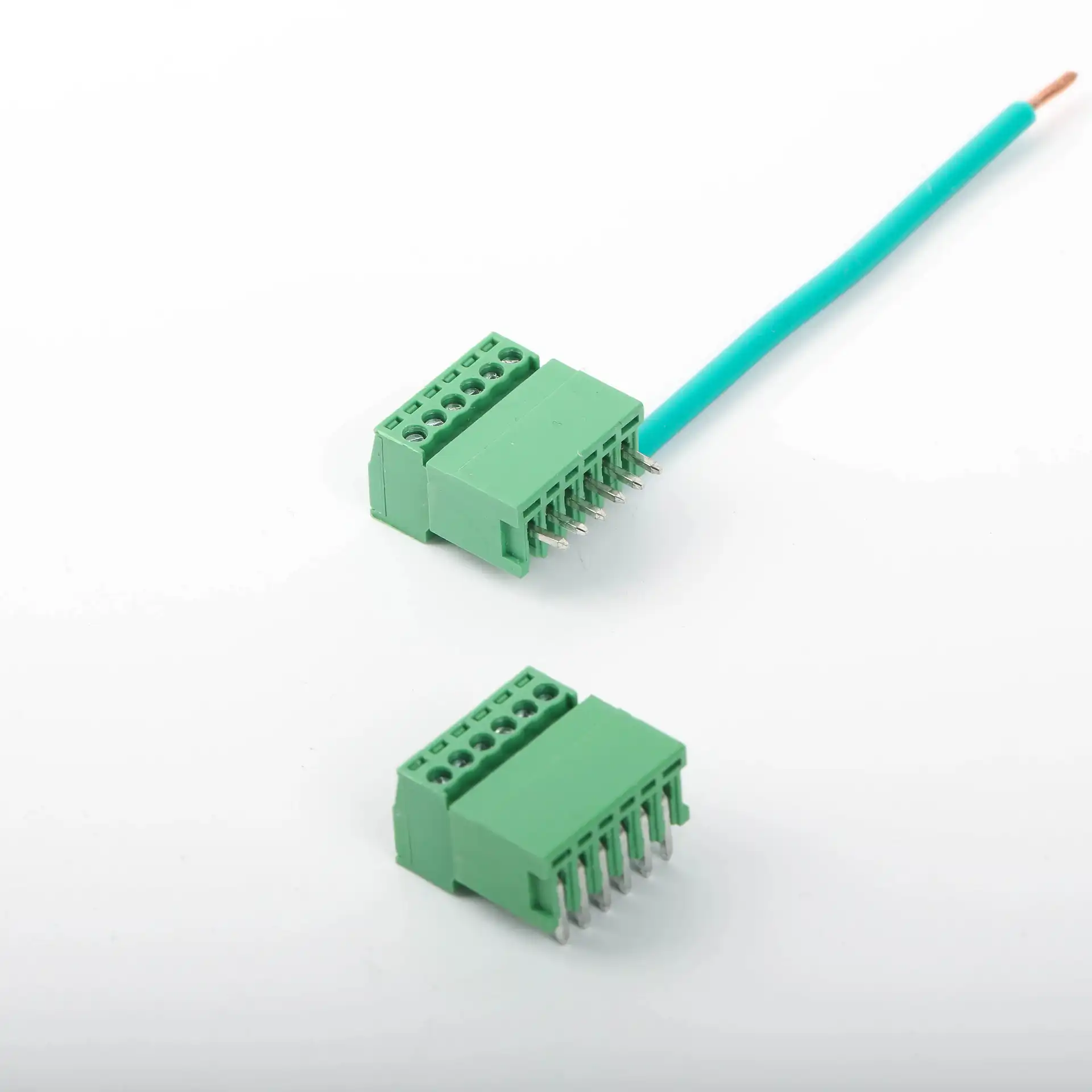
Plug-in / PCB Terminal Blocks for Modular Wire-to-Board Wiring
Source pluggable PCB terminal systems, PCB headers, PCT push-in wire connectors and compact distribution products for control boards, power modules, automation equipment and OEM electrical assemblies. SENTOP supports pitch and pole matching, drawing review, samples and bulk supply.
What is a plug-in PCB terminal block?
A pluggable PCB terminal block is a two-part connection system. The wire-side plug terminates the conductors, while the mating header is mounted on the printed circuit board. The plug can be disconnected from the header without removing each wire, which can simplify equipment assembly, module replacement and field service.
A fixed PCB terminal block is different: the conductor connection and solder pins belong to one component mounted directly on the PCB. Both structures are useful, but their footprints, service methods and purchasing requirements are not interchangeable.
Wire-side plug
Terminates the field conductor using the connection method supported by the selected model.
PCB header
Provides the mating contact and solder-pin interface to the printed circuit board.
Mating interface
Pitch, pole count, keying, housing profile and contact system must match between the two halves.
PCB design interface
Footprint, pin dimensions, orientation, clearance and soldering process must suit the board design.
Choose the product direction by connection interface
The category includes true wire-to-board PCB systems plus supporting push-in and distribution products used in compact electrical assemblies. Confirm the mounting and connection interface before comparing models.
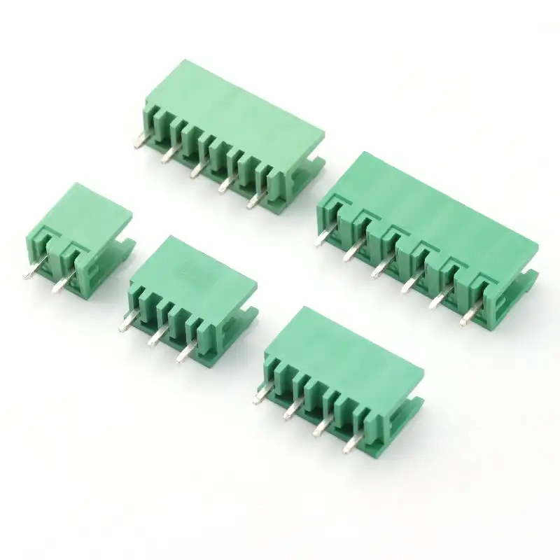
Pluggable PCB Terminal Blocks
Wire-to-board connection systems for control boards, power modules, controllers and serviceable electronic equipment. The wire-side connector and board-side header must be selected as one compatible system.
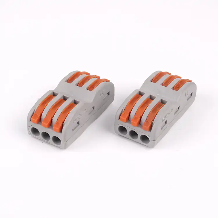
Push-In Wire Connectors
Compact wire-to-wire connectors for lighting, junction boxes, small equipment and quick wiring tasks. PCT products do not use the same PCB plug-and-header architecture and should be selected by conductor and circuit needs.
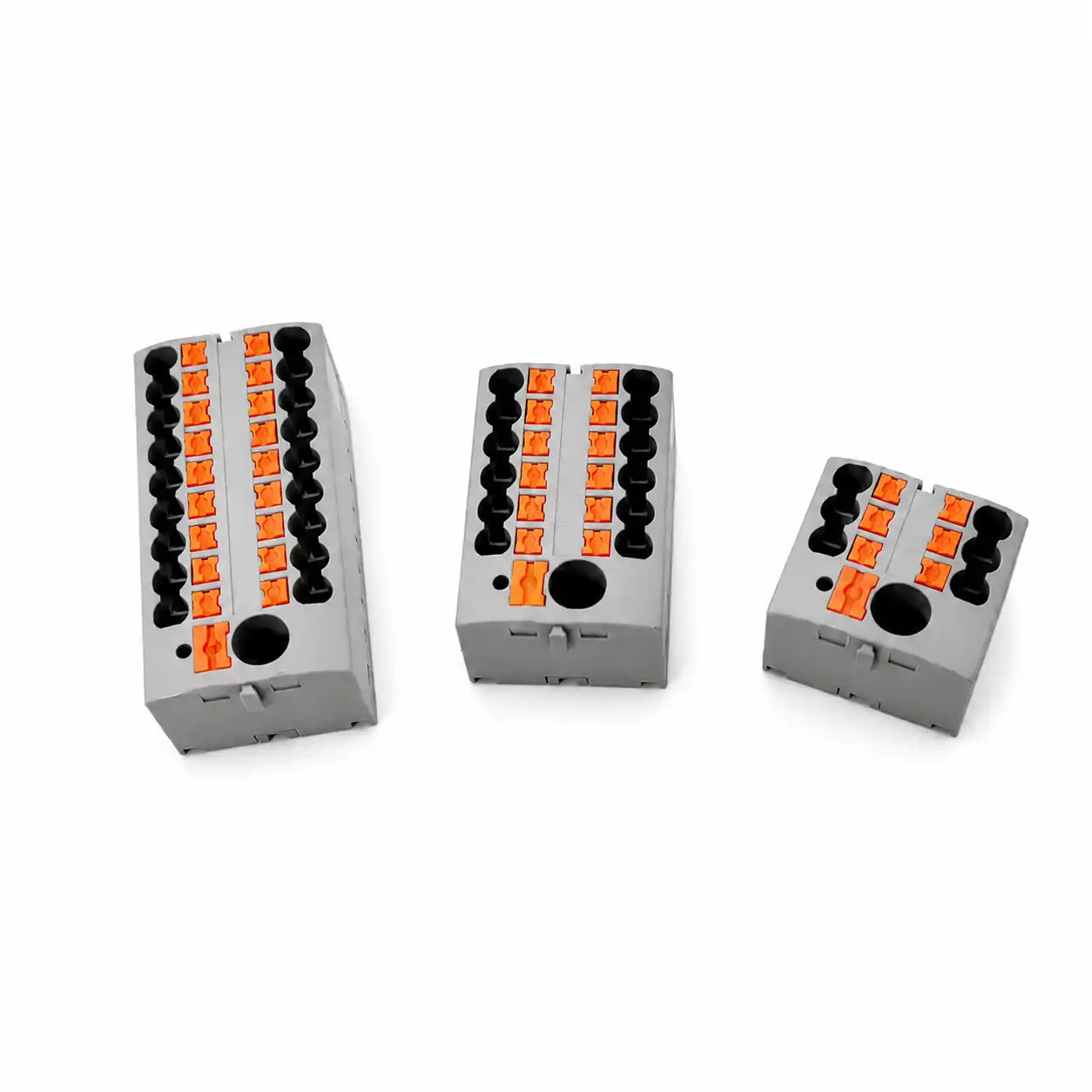
Compact Distribution Blocks
Distribution products for organizing one incoming potential into multiple outgoing connections in control cabinets and compact assemblies. They support cabinet wiring rather than direct PCB solder mounting.
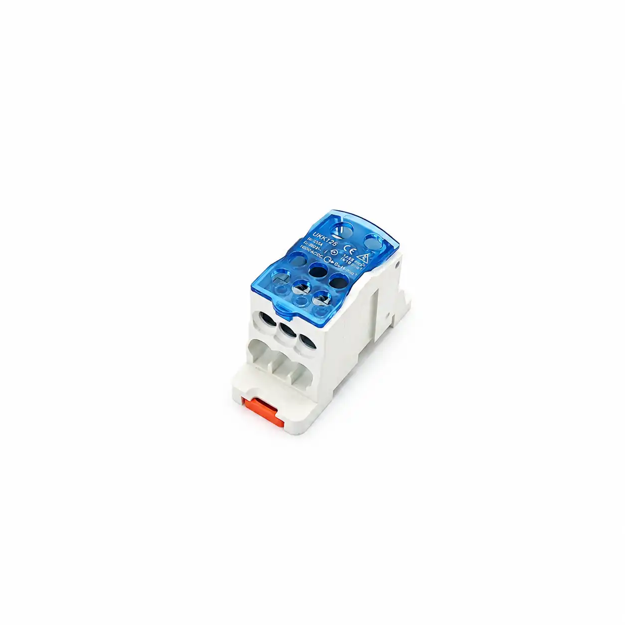
Power Distribution Blocks
Multi-connection distribution blocks for electrical panels, machinery and distribution boxes. UKK products are supporting power-distribution components, not PCB plug-in connectors.
Treat the two mating halves as one connection system
A connector can have the same pitch and pole count as another product but still differ in housing profile, contact geometry, polarization, locking and board orientation.
Confirm the mechanical and electrical interface before board release
The connector decision affects PCB footprint, enclosure clearance, field wiring access and production assembly. Use the exact model drawing rather than a generic terminal-block outline.
Pitch and Poles
Confirm center-to-center spacing, number of positions, overall length and any side wall or grouping requirement.
Do not infer pitch from product appearanceMating Orientation
Review vertical, horizontal or angled mating direction together with wire-entry and operating-tool access.
Check enclosure and service clearancePCB Footprint
Use the exact pin layout, hole dimensions, row spacing, tolerances and component keep-out information.
Approve from the selected model drawingConductor Interface
Confirm wire construction, cross-section, ferrule use, strip length and connection or release procedure.
Match conductor preparation to the modelElectrical Requirement
Review current, voltage, insulation, temperature and applicable product requirements for the exact application.
Use model-specific approved technical dataCoding and Retention
Check polarization, keying, locking, flange or strain-relief needs where incorrect mating or cable movement is a concern.
Confirm available options by seriesPrepare the information needed for model matching
A useful RFQ should describe both the board side and wire side. Provide the available drawing, sample or old model even when some specifications are still being confirmed.
| Selection item | Information to provide | Why it matters | Helpful evidence |
|---|---|---|---|
| Connection architecture | Pluggable wire-to-board, fixed PCB terminal, wire-to-wire or distribution | Separates products with completely different interfaces | System diagram or application photo |
| Pitch and poles | Center spacing, number of positions and grouping | Defines connector length, mating pattern and PCB layout | Drawing or measured sample |
| Plug and header | Complete model codes for both mating halves | Confirms housing, contact and mechanical compatibility | Front, side and mating photos |
| Conductor | Solid or stranded wire, cross-section, ferrule and strip length | Determines the suitable wire-side connection and preparation | Cable specification |
| Electrical requirement | Operating current, voltage, circuit type and applicable standard | Guides model-specific rating and insulation review | Equipment specification |
| PCB interface | Footprint, pin dimensions, hole size, orientation and soldering process | Ensures the header can be integrated into the released board design | PCB layout and selected model drawing |
| Mechanical needs | Keying, locking, flange, strain relief, enclosure and service clearance | Reduces mismating and installation interference | 3D layout or enclosure drawing |
| Commercial data | Quantity, sample need, packaging, labeling, destination and documents | Supports quotation, production planning and repeat-order control | RFQ or BOM sheet |
Replacement reminder: Pitch and pole count are only two checks. Compare the exact plug/header models, housing shape, keying, contact structure, board pins, orientation, wire range and electrical data before approving a replacement.
Pluggable, fixed PCB, PCT or distribution: which structure fits?
These products can appear in the same equipment but solve different connection problems. Choose by interface and service requirement first.
| Product direction | Primary interface | Suitable starting point | Main confirmation |
|---|---|---|---|
| Pluggable PCB system | Wire-side plug mates with board-mounted header | Serviceable modules, controllers, power supplies and pre-wired harnesses | Matched pair, pitch, poles, orientation and footprint |
| Fixed PCB terminal | Conductor connects directly to one PCB-mounted component | Permanent board connection without a detachable plug | Footprint, wire entry, connection method and access |
| PCT connector | Compact wire-to-wire push-in connection | Lighting, junction boxes and small equipment wiring | Wire type, ports, rating and environment |
| PTFIX distribution | One potential distributed to multiple conductors | Compact cabinet control-voltage or signal distribution | Feed-in, outputs, conductor ranges and mounting |
| UKK distribution | Panel-mounted multi-wire power distribution | Electrical panels and larger conductor branching | Input/output sizes, rating, cover and mounting |
Match the connector system to the equipment workflow
Application names provide context, but the final connector still depends on board layout, circuit data, conductor, service access and production process.
Industrial control boards
Connect field or cabinet wiring to controller PCBs while allowing board modules to be disconnected for assembly or service.
Typical direction: matched PCB plug + headerPower supplies and converters
Provide detachable input, output or control connections around PCB-based power modules and enclosed devices.
Typical direction: model-specific PCB connector systemAutomation and OEM equipment
Pre-wire cable assemblies and repeat an approved plug/header interface across machines or production batches.
Typical direction: controlled BOM and harness preparationLighting and junction boxes
Join compact internal or field conductors where a separate printed circuit board interface is not required.
Typical direction: PCT push-in wire connectorsControl-voltage distribution
Distribute a common control or signal potential to multiple circuits in a compact cabinet layout.
Typical direction: PTFIX distribution blocksPanel power distribution
Organize larger incoming and outgoing conductor connections inside panels, machines and distribution boxes.
Typical direction: UKK power distribution blocksFrom a PCB drawing or product sample to a confirmed quotation
Send the available information even if the model number is missing. SENTOP can review the connection architecture, identify missing plug/header data and organize a quotation for samples, production or replacement projects.
Share the interface data
Send models, photos, pitch, poles, wire information, electrical requirement, PCB layout and quantity.
Review the matched system
Confirm plug, header, footprint, orientation, connection method, locking and packaging details.
Approve sample or quotation
Check mating fit, PCB integration, technical documents, labels and delivery plan before bulk ordering.
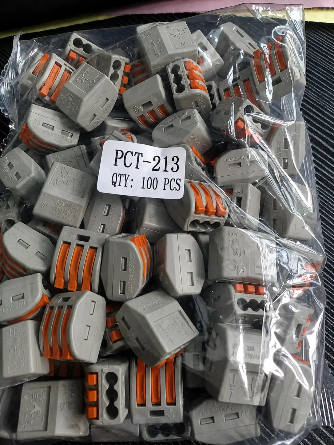
Keep mating parts and order identity under control
A small model difference can change the mating interface or PCB footprint. Product code, poles, pitch, orientation, accessories, quantity and packaging should remain traceable to the approved BOM.
Plug-in and PCB terminal block questions
Initial answers for PCB designers, equipment engineers, OEM manufacturers, distributors and project buyers.
What is the difference between a pluggable PCB terminal block and a fixed PCB terminal block?
A pluggable system uses a wire-side plug and a separate PCB-mounted header, allowing the wired connector to detach from the board. A fixed PCB terminal block is one component soldered to the board, and the conductor connects directly to that component.
What information is needed to select a PCB plug-in terminal block?
Provide the pitch, pole count, plug and header models, wire size, connection method, current, voltage, mating orientation, PCB footprint, soldering process, locking requirement, quantity and application.
Does the same pitch mean two PCB connectors are compatible?
No. Products with the same pitch can differ in contact geometry, housing profile, keying, locking, orientation, pin dimensions and ratings. Confirm the complete mating family and model codes.
Should I order both the plug and PCB header?
For a new pluggable connection, both mating halves are normally required unless one side is already installed or stocked. State the quantity required for each plug and header model so the quotation reflects the complete system.
What should a PCB designer confirm before releasing the board?
Use the selected header drawing to confirm pin layout, hole size, row spacing, orientation, component dimensions, tolerances, keep-out space, mating clearance and soldering process.
Can stranded wire be used with PCB plug-in terminal blocks?
Many models support stranded conductors, but the permitted conductor range, ferrule requirement, strip length and operating method are model-specific. Check the selected product instructions.
Are PCT, PTFIX and UKK products PCB plug-in connectors?
No. PCT is a compact wire-to-wire push-in product direction, PTFIX is used for compact potential distribution, and UKK is used for panel power distribution. They are included as related wiring products but use different interfaces.
How do I replace an existing pluggable terminal block?
Send the complete plug and header model numbers, photos, pitch, poles, dimensions, keying, orientation, wire data, PCB footprint and electrical requirement. A physical sample can help verify mating fit.
Can SENTOP supply samples and mixed pole counts?
Sample and mixed-model availability depends on the selected products and project requirement. Send the required plug/header pairs, pole counts, quantities and test purpose for review.
Send your plug, header, PCB drawing, product photo or BOM for review.
Request pluggable PCB terminal systems, PCT wire connectors, PTFIX or UKK distribution products, replacement matching, samples or organized bulk supply.
