
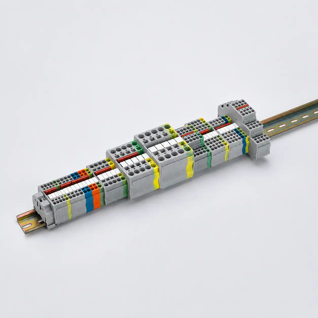
Terminal Block Accessories Guide
Choose Terminal Block Accessories for a Complete, Compatible DIN Rail Assembly
Match end clamps, end covers, partitions, bridges, markers, test accessories and DIN rails to the exact terminal series and terminal-strip drawing. This guide helps panel builders and buyers turn loose terminal positions into an assembly-ready BOM.
Answer First
Which accessories does a terminal strip need?
A typical DIN rail terminal strip needs a mounting rail, end clamps, the correct end covers for open terminal sides, markers for identification and bridges where common potentials are distributed. Partitions, test plugs, warning labels and other functional accessories are added only where the circuit and terminal design require them.
Accessories are series-specific components. Similar shape, pitch or color does not prove compatibility. Release each accessory against the exact terminal model and the approved strip layout.
Freeze the terminal family
Record manufacturer, series, exact terminal code, function, cross-section, levels and pitch.
Draw every rail position
Show terminal order, PE points, profile transitions, circuit groups, spare positions and rail breaks.
Assign accessory interfaces
Match end profile, bridge channel, marker slot, test opening, rail foot and safety separation.
Release codes and quantities
Keep accessory item codes, locations, counts, printing data and revisions in the same terminal-strip BOM.
Assembly Map
Understand where each accessory works in the finished terminal strip
The terminal strip is one coordinated mechanical and electrical system. Use the strip drawing to identify each accessory location before calculating quantity.

Interactive Planning Tool
Build a practical starter accessory BOM
Enter basic terminal-strip conditions. The result estimates planning quantities and creates a summary for the enquiry popup. Exact accessory codes still require the terminal series and drawing.
Accessory Types and Selection
Choose each accessory from its working interface
The useful question is not only “what is this accessory called?” but “what exact mechanical, electrical or identification interface must it match?”
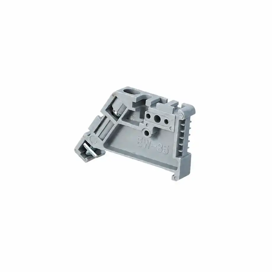
End Clamps and End Brackets
Secure a terminal group on the rail and help resist movement during wiring, transportation and service. Count them from physically separated groups, not simply from total terminal quantity.
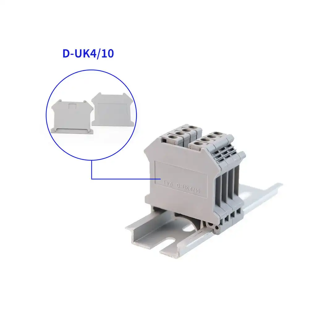
End Covers and Partition Plates
End covers close open housing profiles. Partitions create deliberate separation or visual boundaries. Their contour, thickness and installation side must match the terminal geometry and strip layout.
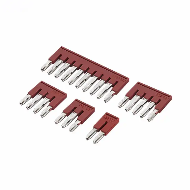
Fixed Bridges and Jumpers
Connect selected terminal positions to a common potential. Bridge design must agree with terminal pitch, insertion channel, pole count, circuit grouping and the intended current path.
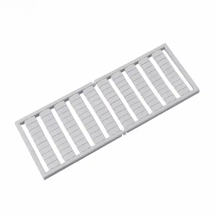
Marker Strips and Group Labels
Connect the physical assembly to the terminal plan, conductor labels and maintenance procedure. Marking should remain visible after wiring and must fit the terminal marker slot.
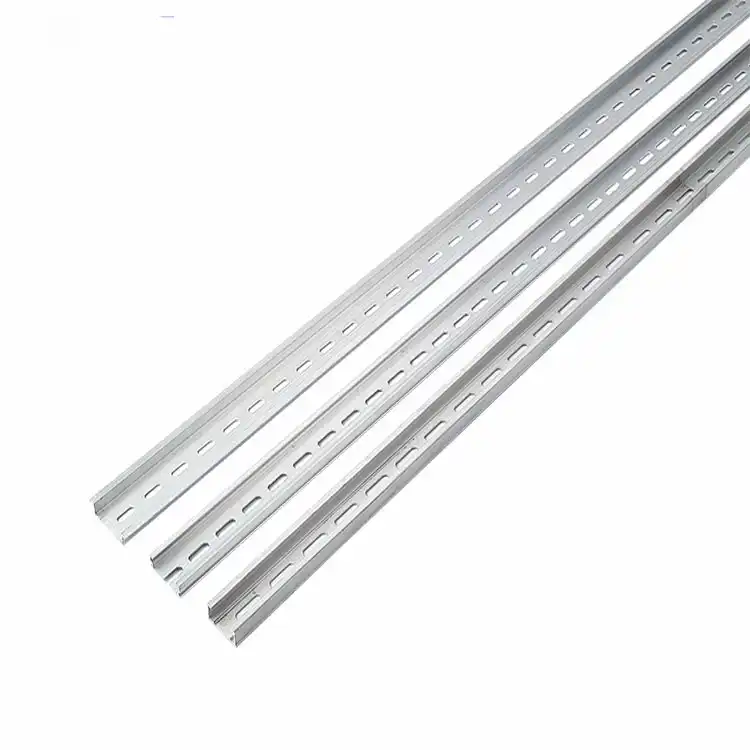
DIN Rails and Rail Supports
Provide the mounting interface for terminals and end clamps. The rail selection also affects PE terminal performance, mounting height, stiffness, surface treatment and cabinet layout.
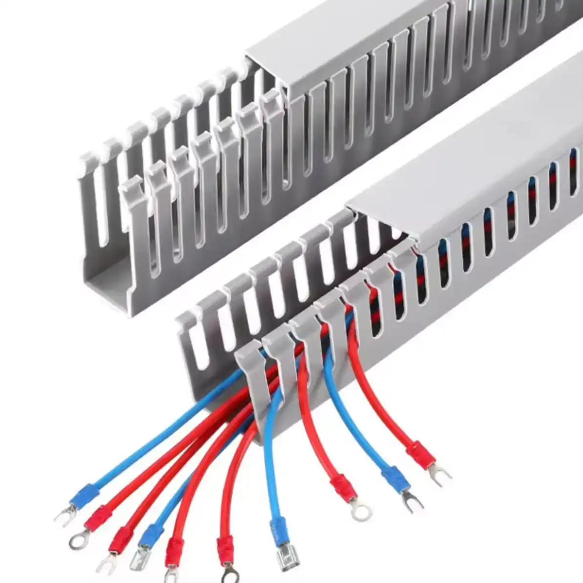
Wiring Ducts and Routing Space
Wiring duct is not fitted to the terminal itself, but it determines usable conductor entry, bend radius, inspection access and maintenance space around the terminal strip.
Compatibility Check
Similar dimensions do not mean interchangeable accessories
Terminal accessories depend on proprietary interfaces. Use the exact item code or written compatibility evidence before ordering replacements or mixed-family assemblies.
Quantity Planning
Calculate from positions, groups and exposed interfaces
Use these planning rules to organize the BOM. Replace every estimate with the final strip drawing and exact accessory item code before release.
| Accessory | Starting quantity logic | What changes the final count |
|---|---|---|
| End clamps | Begin with two for each separately restrained terminal group. | Rail breaks, support brackets, mixed devices, spare zones and project vibration requirements. |
| End covers | Count each exposed open terminal side or housing profile transition. | Terminal symmetry, left/right profile, multi-level shape, adjacent compatible housings and partition use. |
| Partition plates | One at each specified circuit, voltage or functional separation boundary. | Required spacing, neighboring accessories, terminal function, local rules and drawing conventions. |
| Terminal markers | Start from the number of positions that require identification. | Multi-level terminals, duplicate side marking, group labels, spare terminals and custom printing format. |
| Fixed bridges | One compatible bridge pattern for each documented common-potential group. | Group length, skipped poles, step-down transitions, multiple bridge channels and current distribution. |
| Test accessories | Count only the planned measurement or service points plus approved service spares. | Terminal function, test procedure, plug diameter, isolation method and maintenance kit policy. |
| DIN rail | Sum terminal widths, end clamps, covers, spacers and approved spare capacity. | Cut allowance, mounting holes, rail supports, device clearances, bend radius and cabinet layout. |
| Wiring duct | Calculate from routing length and required cross-section around the terminal strip. | Fill ratio, conductor exits, slot pitch, bend radius, cover access and future wiring allowance. |
Bridge, Marking and Service Design
Three accessory systems deserve a separate drawing check
These items can change the electrical function or the ability to commission and maintain the equipment. Treat them as design elements, not packing extras.
Continuous Commoning
Use a continuous bridge only where every included position belongs to the same potential and the bridge current path is approved.
Grouped or Skipped Poles
Document each included and excluded position. Do not improvise a skipped pattern from a bridge not intended for modification.
Terminal and Level IDs
Keep numbering unique and readable for every position and level, including PE, spare and disconnect terminals.
Group and Device Labels
Add labels where operators need fast orientation between terminal groups, field devices, voltages or functions.
Test and Disconnect Points
Define normal state, operating sequence, test plug, isolation boundary and restoration procedure before selecting accessories.
Approved Spare Kit
Keep only useful series-specific spares with the equipment: markers, bridges, covers, clamps and test items tied to released codes.
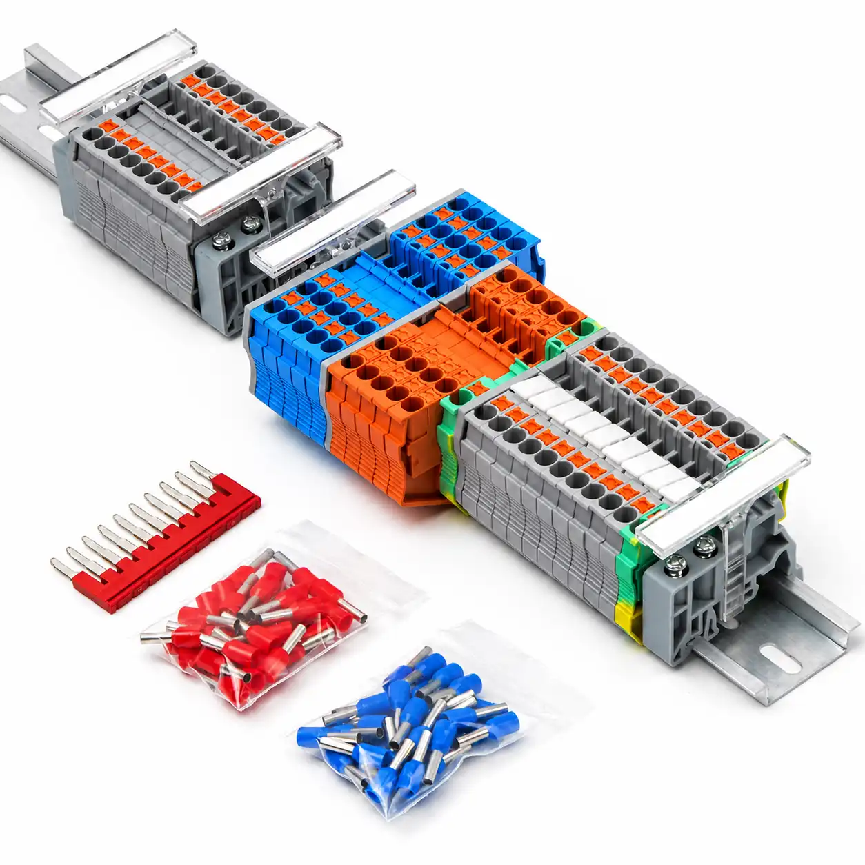
From Drawing to Released BOM
Approve the accessory system before repeat production
A first-article terminal strip reveals problems that a spreadsheet cannot: cover gaps, blocked tools, unreadable labels, loose groups, wrong bridge positions or insufficient wiring space.
Avoid Accessory Failures
Small mismatches create large assembly problems
Use these checks during design, purchasing, incoming inspection and first-article approval.
Standards and Evidence
Use the current standard with model-specific compatibility data
Standards organize the terminal-block review, while the manufacturer defines which accessories are compatible with each model. Confirm the applicable edition, exact product scope and destination-market requirements.
IEC 60947-7-1:2025
The current IEC terminal block standard covers screw-type and screwless-type clamping units for copper conductors and includes terminal-block characteristics and verification requirements. Use exact model data for the complete assembly.
View the IEC publication →IEC 60947-7-2
PE and PEN terminal functions require their own protective conductor review, including the connection between conductor and supporting rail. Do not treat a green-yellow housing as proof of compliance.
View the IEC publication →Accessory System Evidence
Keep series compatibility tables, drawings, item descriptions and installation instructions. Industry accessory systems typically organize bridges, end covers, partitions, markers and test components around a defined terminal family.
Review an industry reference →Prepare a Useful Enquiry
Send three groups of data for faster accessory matching
One terminal model, terminal-strip drawing or clear sample photo can prevent several rounds of compatibility questions.
Terminal and rail identity
Brand, series, exact terminal codes, photos, conductor range, pitch, levels, terminal quantity, rail profile and rail sections.
Electrical and marking plan
Potential groups, bridge positions, PE terminals, test points, terminal numbers, printed text, colors and drawing references.
Supply requirements
Accessory-only or assembled-strip scope, quantity, destination, standards, documents, packaging, labels and delivery schedule.
Terminal Block Accessories FAQ
Buyer and panel-builder questions
Use these answers to define an accessory direction. Final release still depends on exact terminal models, drawings and project rules.
Are terminal block accessories interchangeable between brands?
Do not assume so. Bridges, covers, markers, clamps and test accessories can use brand- and series-specific interfaces. Approve interchangeability only from documented compatibility or a controlled sample review.
How many end clamps does a terminal strip need?
A common starting point is two end clamps for each separately restrained terminal group. Rail breaks, mixed devices, supports and project vibration conditions can change the final arrangement.
When is an end cover required?
An end cover is generally used where the side of a terminal housing leaves an open profile that must be closed. The exact requirement and left/right location depend on the terminal model and neighboring components.
What is the difference between an end cover and a partition plate?
An end cover closes the exposed side profile of a terminal. A partition plate creates additional separation or a visible boundary at a selected point. Some product systems use different shapes and item codes for these functions.
Can a fixed bridge be cut to create skipped poles?
Only when the bridge system and instructions permit that modification. Otherwise use a designated skipped-pole, staggered or custom pattern. Record every bridged position on the terminal plan.
Does a bridge change the current rating?
The bridge becomes part of the current path, so its model-specific current data, contact arrangement and the distribution of load among positions must be reviewed. Do not apply the terminal's headline current automatically to every bridged configuration.
How should terminal markers be ordered?
Provide the exact terminal family, marker slot, pitch, marker format, text sequence, character limits, color and quantity. Include terminal numbers, multi-level positions and group labels in one approved marking file.
How do I calculate DIN rail length?
Add the widths of all terminals, end covers, partitions, spacers, end clamps and approved spare positions, then include installation and mounting clearances. Confirm the final cut length from the panel layout.
Can PE terminal blocks use any DIN rail?
No assumption should be made. Verify the PE terminal, rail profile, rail material and surface, mounting method and protective conductor data as one approved arrangement.
What information is needed to replace an unknown accessory?
Send the terminal and accessory markings, full strip photos, close views from both sides, rail profile, dimensions and the location in the assembly. A physical sample can help where the model cannot be identified.
Should spare accessories be supplied with the panel?
A controlled service kit can be useful for repeat equipment or remote sites. Include only released series-specific items and identify their item codes, purpose and storage quantity.
Can SENTOP supply a complete assembled terminal strip?
SENTOP can review the requested supply scope, including terminals, compatible accessories, marking, rail preparation, assembly, packaging and documentation. Send the terminal-strip drawing, quantity and destination for confirmation.
Continue Your Project
Move from guide to the relevant product path
Terminal Block Accessory Support
Send one accessory model or a complete terminal-strip BOM
SENTOP supports accessory matching, replacement review, terminal-strip BOMs, samples, OEM requirements and bulk supply for panel builders, equipment manufacturers, distributors and project buyers.
