

Reading terminal block markings sounds simple—until you’re assembling a panel that must pass both UL and IEC inspections. Current vs. voltage, Pollution Degree vs. Overvoltage Category, heat‑rise vs. power dissipation tests—the details matter, and they’re not identical across standards. This guide gives you a practical, field‑ready workflow to interpret terminal block markings in dual‑standard builds without wading through paywalled standards.
Key takeaways
- Don’t assume UL and IEC ratings match. Check both sets of markings and the datasheet.
- Voltage under UL 1059 ties to spacings; IEC 60947‑7‑1 relies on insulation coordination (PD/OvCat/impulse).
- Treat ambient temperature and grouping seriously; use the manufacturer’s derating curve for current.
- If a block lacks marked SCCR, UL 508A defaults to 10 kA when determining panel SCCR; coordinate upstream OCPD accordingly.
- Use green‑yellow only for PE, never for neutral; follow IEC color/symbol conventions.
Quick field‑read: terminal block markings at a glance
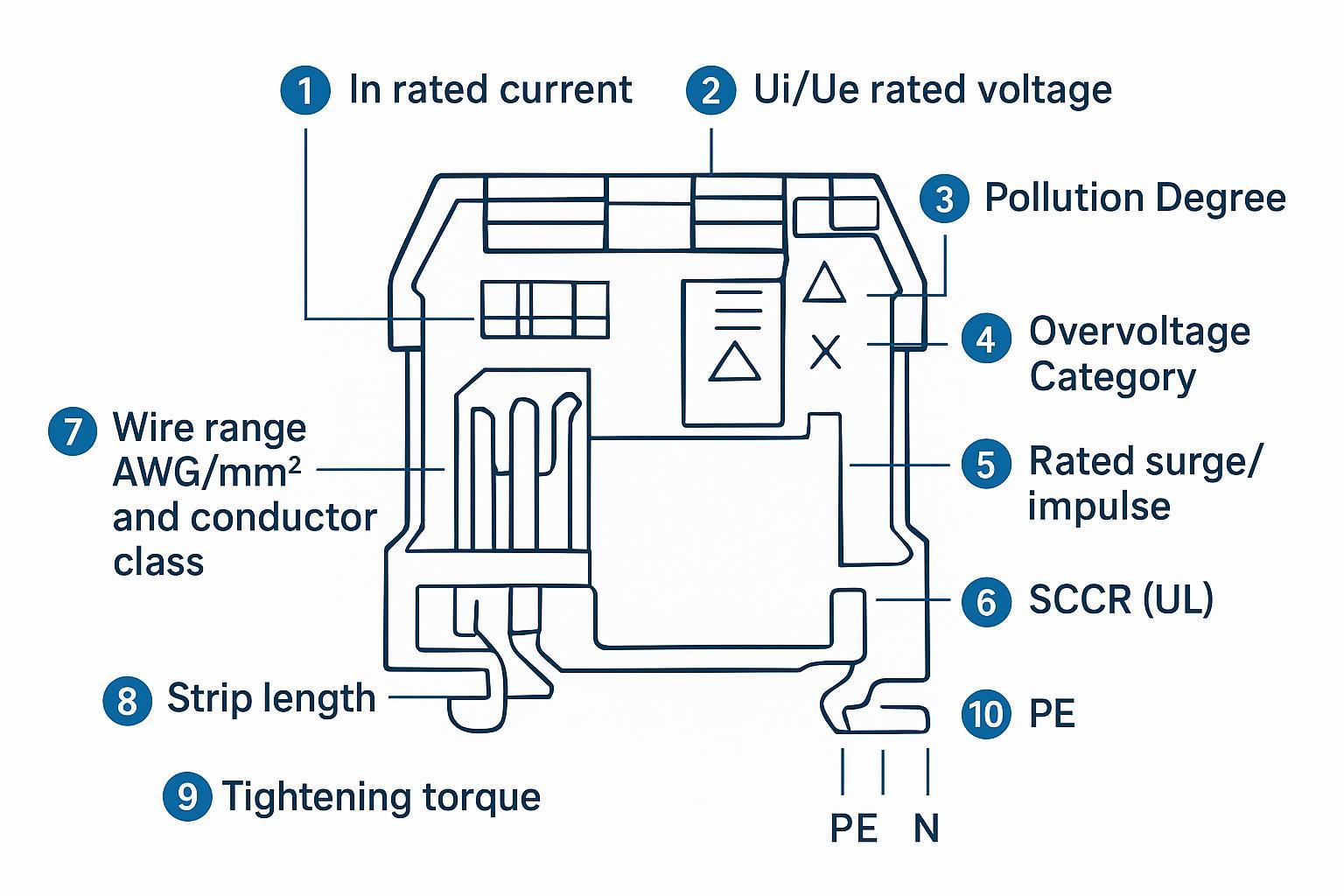
- In (rated current) and Ui/Ue (voltage): Often printed on the block body or shown prominently in the datasheet.
- Pollution Degree (PD) and Overvoltage Category (OvCat): Typically listed in datasheets and compliance pages; sometimes summarized as PD3/Cat III with a surge value.
- SCCR (UL): May be printed or only provided in UL files/manufacturer notes.
- Wire range (AWG/mm²), strip length, and tightening torque: Check the “Connection data” or installation instructions.
- PE/N symbols and colors: Green‑yellow for PE, blue and “N” for neutral per IEC conventions.
For a quick primer on UL spacing vs. IEC insulation coordination and why the numbers diverge, Eaton’s selection note summarizes both approaches in plain language; see the manufacturer overview in How to select a terminal block and spacings context from the Digi‑Key application note with UL 508A references.
Dual‑standard cross‑check workflow (5 steps)

- Identify all visible markings: In, Ui/Ue, PD, OvCat, surge, SCCR (if present), wire range, torque, strip length, PE/N.
- Pull the datasheet and installation instructions to confirm any missing values and the test basis (UL 1059 vs. IEC 60947‑7‑1).
- Verify environment fit: For IEC, confirm PD and OvCat align with the installation; for UL, confirm spacings/voltage class for the applied voltage.
- Apply thermal realism: Use the derating curve for your cabinet ambient and wiring density; adjust current accordingly.
- Document evidence: Record UL file/category, SCCR basis, and links to datasheet/UL resources in your build log.
Cross‑check matrix (field use)
| Marking | Where to read | IEC 60947‑7‑1 perspective | UL 1059 perspective | Pass/Fail quick rule | Evidence link |
|---|---|---|---|---|---|
| Ue/Ui (voltage) | Body/datasheet | Based on insulation coordination (PD, OvCat, impulse) | Based on clearances/creepage and dielectric withstand | Use the lower allowable voltage when in doubt; ensure creepage/clearance for IEC and UL spacings for UL | See Digi‑Key spacing note for UL 508A/1059; see Weidmüller IEC testing overview |
| In (current) | Body/datasheet | Power dissipation/temperature‑rise criteria | Heat‑rise per pole criteria | Apply manufacturer derating at actual ambient and wiring density | Phoenix electrical tests summary |
| Pollution Degree | Datasheet | Drives creepage along with material group | Not a marking driver; UL focuses on spacings classes | PD3 typical for industrial cabinets; confirm unless environment is controlled | Weidmüller IEC testing overview |
| OvCat + surge | Datasheet | Determines required impulse withstand/clearance | Managed via spacing/withstand tests | Cat III usually expected in panels; confirm surge value matches nominal system | Phoenix UT product page example |
| SCCR | Print/file | Not applicable (IEC) | Needed for UL 508A panel SCCR | If unmarked, treat as 10 kA per UL 508A SB; otherwise use marked value | UL SCCR guidance |
| Wire range (AWG/mm²) | Datasheet | Lists solid/stranded/ferrule classes | Lists AWG/Cu; field wiring notes | Match wire class and ferrule use exactly; don’t mix ranges | Eaton selection note |
| Strip length & torque | Datasheet/inst. | Installation data | Installation data | Use the specified strip/tightening torque to avoid hot joints | Rockwell/Phoenix datasheets |
| PE/N color & symbol | Body/datasheet | Green‑yellow reserved for PE (IEC 60445); “N” for neutral | UL accepts PE/N symbols; color expectations follow IEC/local code | Don’t use green‑yellow for anything except PE | Test report citing IEC 60445 |
External evidence sources cited in the table above: the Digi‑Key spacing application note for UL 1059/UL 508A requirements (2023), Weidmüller’s IEC electrical testing summary (2023–2026), Phoenix Contact’s electrical tests and product examples (2021–2026), UL’s SCCR determination guidance, and a test report referencing IEC color conventions.
Current and voltage ratings: why UL and IEC differ on the same block
Under UL 1059, the terminal block’s voltage rating is rooted in minimum clearances/creepage and dielectric withstand tests; common classes include 150 V, 300 V, and 600 V. Current is validated by heat‑rise per pole. By contrast, IEC 60947‑7‑1 follows IEC 60947‑1 insulation coordination: voltage capability is a function of Overvoltage Category, Pollution Degree, material group, and impulse withstand; current ties back to power dissipation and temperature‑rise limits. That’s why you’ll often see dual markings like “UL 600 V” and “IEC 800 V” on one part.
- Practical move: For dual‑market panels, adopt the stricter of the two for the specific installation. Cross‑verify spacings for UL panels using the UL 508A framework summarized in the Digi‑Key spacing note: see the Spacing Requirements for Power Distribution and Terminal Blocks in Control Panels (2023).
- Background reading: Eaton’s How to select a terminal block gives a quick comparison of UL 1059 and IEC 60947‑7‑1 and the implications of each methodology.
Pollution Degree and Overvoltage Category: getting environment right
Pollution Degree (PD) defines how contamination affects insulation. In most industrial cabinets, PD3 is assumed unless you can prove a controlled environment. Overvoltage Category (I–IV) sets expectations for transient levels: Cat III is typical for fixed installations inside control panels.
- Why it matters: PD and OvCat determine required creepage/clearance and rated impulse withstand under IEC, and they explain why an “IEC 800 V” marking might still require careful panel layout. Phoenix and Weidmüller provide accessible overviews of PD, OvCat, and impulse withstand in their technical resources. For a broader standards overview tailored to panel builders, see the internal guide to certification standards for terminal blocks worldwide on our site.
Temperature rise and derating: convert a label into a safe current
A marking like “In 41 A” is only valid at the test ambient and wiring conditions used by the manufacturer. Most manufacturers publish derating curves (current vs. ambient) to help you translate that number into real cabinets.
- Field rule of thumb: At cabinet ambients above 40 °C, reduce current per the datasheet’s derating curve. If your wiring density is higher than the test configuration, be conservative.
- Worked example: A terminal block family documented by Phoenix Contact limits temperature rise to ≤ 45 K and specifies that ambient plus self‑heating must remain below the upper limiting temperature. If your cabinet runs at 55 °C and the curve shows 80% of nominal at 55 °C, a 41 A nominal becomes ~33 A. Always cite the actual curve from the specific product PDF.
- Evidence: See Phoenix’s electrical tests for terminal blocks and product PDFs that state the 45 K criterion and upper‑limit temperature condition.
For material‑related thermal behavior and long‑term durability considerations, our internal article on how material selection influences terminal block durability provides additional context you can apply during selection and layout.
SCCR and coordination in UL 508A panels
The panel’s nameplate SCCR is limited by the lowest‑rated component. If a terminal block doesn’t have a marked SCCR, UL 508A Supplement SB instructs you to use a default of 10 kA for the panel SCCR calculation. You can often raise the overall SCCR by selecting a current‑limiting overcurrent protective device (OCPD) upstream so the let‑through energy stays below the weakest component capability.
- Starting point: UL’s Determining Short‑Circuit Current Rating (SCCR) for machinery and panels summarizes the method with examples and ties directly to the SB process.
- Watchlist: Standards update notices, like Intertek’s 2024 SUN for UL 1059, provide recency context for marking and evaluation practices that affect how manufacturers present SCCR.
If you’re planning selections holistically, our internal piece on systematic selection of terminal blocks for electrical panels can help you avoid downstream coordination surprises.
Mechanical data that actually matter: wire range, torque, strip length

Connection reliability lives here. Match the datasheet exactly: wire class (solid/stranded), ferruled vs. bare, AWG and mm² ranges, required strip length, and tightening torque. Incorrect strip length reduces contact area; incorrect torque leads to heating or conductor damage.
- Datasheet examples: Rockwell’s 1492 series technical data and Phoenix Contact product pages clearly show wire ranges, strip lengths, and tightening torques. Use those figures as the single source of truth for installation.
- Tip: If ferrules are used, verify whether the permissible ranges change; many datasheets list separate limits for ferruled conductors.
For a broader refresher on common specifications and how to trade off conductor size, insulation, and device selection, see our internal complete guide to common specifications of terminal blocks.
Troubleshooting: real problems, fast fixes
Mismatched UL/IEC voltage ratings. You’ve got 600 V under UL and 800 V under IEC. Which applies? For a North American UL 508A panel, use 600 V and confirm spacings within that class. For an IEC‑only export build, verify OvCat and PD, then design creepage/clearance accordingly.
Borderline wire range with ferrules. Your conductor is within mm² but outside the AWG range listed for ferruled wires. Don’t squeeze it in. Change the ferrule/wire size or select a block with the correct ferruled range; revise torque per the datasheet.
Hot spot during FAT. IR images show a terminal running > 30 K above ambient at 80% of nominal current. Suspect torque or strip length first. Re‑terminate to the stated strip length and retorque to specification; if temperature stays high, apply the derating curve or split the load across parallel poles where permitted.
Unmarked SCCR in a high‑fault location. Available fault current is 22 kA, but the terminal block isn’t marked. Treat it as 10 kA for SCCR, then add a current‑limiting fuse upstream and verify let‑through per the fuse’s charts to elevate the branch SCCR.
Color confusion on neutral bars. A technician labeled neutrals with green‑yellow tape. That fails IEC identification. Relabel neutrals in blue (and “N”), reserve green‑yellow exclusively for PE, and update your shop standard.
Mixed PD assumptions inside one cabinet. Some parts listed PD2, others PD3. Base your IEC creepage/clearance on PD3 unless the entire cabinet environment and ingress protection support PD2; otherwise, you risk under‑spacing.
Different current ratings under UL vs. IEC. Don’t average them. Apply the lower usable current after derating for your real ambient and wiring bundle; document the basis in the panel file.
Torque values missing on the print. If the block body lacks torque, it should be in the datasheet or installation instruction. Never guess; if unavailable, request the documentation from the manufacturer before energizing.
Further resources (neutral, non‑critical zone)
- UL spacing and SCCR context: see the 2023 Digi‑Key application note on UL 1059/UL 508A spacings and a concise UL resource on determining SCCR for machinery and panels.
- IEC testing perspective: Weidmüller’s electrical testing overview and Phoenix Contact’s electrical tests for terminal blocks.
- Standards context and materials: For a consolidated overview of UL and IEC certifications, see our internal guide to certification standards for terminal blocks worldwide, and for thermal/material implications, see our internal materials article.
- Disclosure: Onesto is our product. For a catalog of terminal blocks with UL 1059 and IEC 60947‑7‑1 options summarized by family and certification, see Onesto’s terminal block product page.
External references used in this article (selected):
- Digi‑Key, Spacing Requirements for Power Distribution and Terminal Blocks in Control Panels (2023): UL 1059 and UL 508A spacing summary PDF
- Eaton, How to select a terminal block (UL 1059 vs IEC 60947‑7‑1 overview): Manufacturer selection overview
- Weidmüller, Electrical testing of terminal blocks (IEC concepts): IEC testing summary
- Phoenix Contact, Electrical tests for terminal blocks: Temperature‑rise and derating overview
- UL, Determining Short‑Circuit Current Rating (SCCR) for Machinery and Panels: UL guidance
- Intertek, UL 1059 Standards Update Notice (Rev. 12‑11‑2024): Recency context for UL 1059
Internal resources (contextual reading):
- Standards overview: Guide to certification standards for terminal blocks worldwide
- Selection and specs: Systematic selection of terminal blocks for electrical panels and A complete guide to common specifications of terminal blocks
- Materials and thermal behavior: How material selection influences terminal block durability
- Product catalog (neutral mention with disclosure above): Onesto terminal blocks
Appendix: mini checklist (printable feel)
| Item | What to capture | Verified (Y/N) | Evidence location |
|---|---|---|---|
| Voltage (UL/IEC) | UL class vs IEC Ui/Ue; lower governs for installation | Datasheet/UL note | |
| Current & derating | Nominal In and usable current at cabinet ambient | Datasheet curve | |
| PD & OvCat | PD assumption (usually PD3) and category (usually Cat III) | Datasheet | |
| SCCR | Marked SCCR or 10 kA default per UL 508A SB | UL file/notes | |
| Wire range & class | AWG/mm²; solid/stranded/ferruled | Datasheet | |
| Strip length & torque | Values from install sheet; torque tool setting | Install sheet | |
| PE/N identification | Green‑yellow only for PE; neutrals in blue with “N” | Panel labels | |
| Documentation | UL file number, category code; internal build log link | Panel file |
A last word: terminal block markings are not just labels—they’re constraints. Read them, cross‑check them, and document them so your panel passes the first time. Then future you won’t be hunting for torque values at 2 a.m.
See also
Circuit Breaker Derating: How Ambient Temperature Affects Sizing
Step by Step Guide to Install a Molded Case Circuit Breaker
Rated value of molded case circuit breaker
A Practical Guide to Comparing IEC 60898-1 and IEC 60947-2 Standards
IEC and UL certification requirements for air circuit breakers

Discover more from SENTOP Electrical Co., Ltd
Subscribe to get the latest posts sent to your email.
