
12 Tinned Copper Crimp Terminal Sizes from 22 AWG to 4/0
Use these 12 practical size bands to build a shortlist, then confirm the exact terminal marking, conductor class, stud or contact size, insulation system and approved crimp tool before ordering.
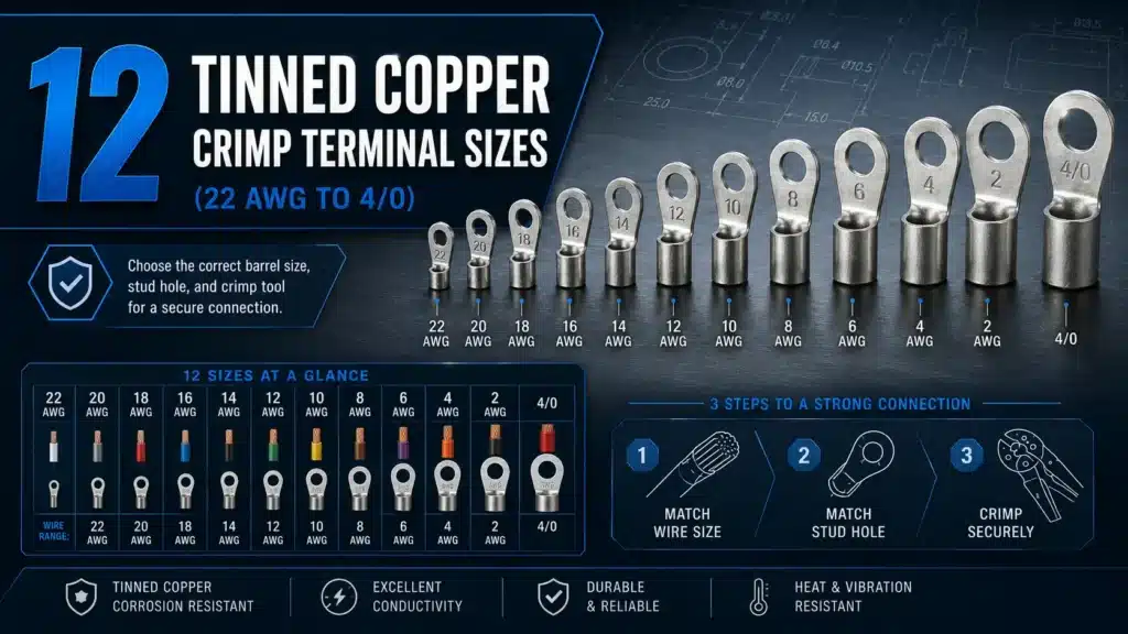
Start with wire size. Finish with the exact system.
A correct terminal is a matched set: conductor, barrel, contact end, tool, die and inspection method.
Record copper or aluminum, solid or stranded, strand class and the insulation outside diameter.
Ring, fork, pin and splice bodies solve different mechanical interfaces; a fitting barrel can still have the wrong tongue.
Tool force alone does not validate a crimp. Check the specified tool, die index, profile and number of compressions.
Verify ratings, conductor range, listing scope, material, plating, drawing revision and lot traceability.
What are the 12 practical tinned copper crimp terminal size bands?
The table below groups three common pre-insulated wire ranges with nine larger compression-lug gauges. It is a sourcing map, not a standards table. An approved part must still state the conductor range and be installed with the terminal maker’s specified tooling.
Small insulated terminals are commonly sold as combined AWG ranges, while larger cable lugs are normally ordered by a single conductor size plus a separate stud-hole option. This is why a useful 22 AWG-to-4/0 purchasing chart can have 12 rows even though the AWG series contains additional individual gauges.
| Band | Conductor range | Nominal area reference | Common terminal format | Stud-hole selection |
|---|---|---|---|---|
| 01 | 22–16 AWG | 0.326–1.31 mm² | Pre-insulated ring, fork, pin or splice | Independent dimension—match the equipment screw/stud |
| 02 | 16–14 AWG | 1.31–2.08 mm² | Pre-insulated ring, fork, blade or splice | Independent dimension—match the equipment screw/stud |
| 03 | 12–10 AWG | 3.31–5.26 mm² | Heavy insulated terminal or small uninsulated lug | Independent dimension—match the equipment screw/stud |
| 04 | 8 AWG | 8.37 mm² | Uninsulated compression ring lug | Select the exact hole diameter from the drawing |
| 05 | 6 AWG | 13.3 mm² | Compression ring lug or power splice | Select the exact hole diameter from the drawing |
| 06 | 4 AWG | 21.2 mm² | Compression ring lug or power splice | Select the exact hole diameter from the drawing |
| 07 | 2 AWG | 33.6 mm² | Standard- or long-barrel compression lug | Select hole diameter, palm width and spacing |
| 08 | 1 AWG | 42.4 mm² | Standard- or long-barrel compression lug | Select hole diameter, palm width and spacing |
| 09 | 1/0 AWG | 53.5 mm² | Power lug, one- or two-hole palm | Select hole diameter, count and center spacing |
| 10 | 2/0 AWG | 67.4 mm² | Power lug, one- or two-hole palm | Select hole diameter, count and center spacing |
| 11 | 3/0 AWG | 85.0 mm² | Power lug, one- or two-hole palm | Select hole diameter, count and center spacing |
| 12 | 4/0 AWG | 107.2 mm² | Heavy-duty power lug or splice | Select hole diameter, count and center spacing |
Reference: NIST Circular 31, Copper Wire Tables; product-range examples: TE Connectivity closed-barrel terminals and splices.
AWG-to-mm² values are nominal references, not automatic substitutions
AWG describes a conductor-size series; metric cable products are specified in nominal square millimetres. A calculated AWG area can help search a catalog, but it does not prove that a metric terminal fits an AWG conductor—or vice versa. Strand count, strand diameter, compaction and conductor class change the physical bundle that enters the barrel.
- 220.326 mm²
- 200.518 mm²
- 180.823 mm²
- 161.31 mm²
- 142.08 mm²
- 123.31 mm²
- 105.26 mm²
- 88.37 mm²
- 613.3 mm²
- 421.2 mm²
- 233.6 mm²
- 142.4 mm²
- 1/053.5 mm²
- 2/067.4 mm²
- 3/085.0 mm²
- 4/0107.2 mm²
IEC 60228:2023 specifies metric nominal cross-sectional areas and addresses solid, stranded and flexible conductors. The class still matters: never “drop one lug size” merely because a cable is fine-stranded. Use a connector specifically documented for that conductor construction.
What does tin plating actually change?
Tin plating is applied over a copper or copper-alloy terminal surface to inhibit corrosion and support a stable, maintainable interface in suitable applications. TE describes its seamless tubular copper power terminals as specially tin plated to inhibit corrosion; that is a defensible benefit. It is not evidence for a universal “40× service life” claim.
Performance depends on coating specification, base metal, porosity, storage, contaminants, sealing, mating material, temperature and the completed joint. A plating thickness such as 3–8 μm may be a supplier specification, but it is not a universal definition of a genuine tinned terminal. Put the required finish and test method on the drawing or purchase order.
- Verify the base material and plating specification, not color alone.
- Use sealed or heat-shrink systems where the application requires environmental sealing.
- For copper-to-aluminum interfaces, use a connector specifically rated for the materials and follow its compound/preparation instructions.

Choose the terminal form after the wire range
Four bodies can accept the same conductor size yet serve completely different connection points. Mechanical retention, service access and the equipment terminal determine the form.
Ring terminal
A closed ring fits over a stud and remains captured until the nut or screw is removed. Use it where positive retention matters and the equipment accepts a bolted tongue.
Specify: wire range + stud hole + palm geometryFork / spade
An open fork can be installed without fully removing the screw. Choose only where the terminal design and equipment instructions allow it, especially in vibration-prone assemblies.
Specify: wire range + fork width + screw sizePin terminal
A formed pin or blade presents a controlled contact shape to a compatible clamp or receptacle. Do not assume it is interchangeable with a wire ferrule or that two pins may share one clamp.
Specify: pin profile + length + receiving terminalButt splice
A butt splice joins conductors end to end. Match both conductor sides, insulation/sealing requirements and the correct crimp location on each barrel end.
Specify: both wire ranges + sealing + environmentColor helps—but markings and tooling control the crimp
Many pre-insulated terminal families use red, blue and yellow sleeves to identify wire-size/tool cavities. Treat that convention as a fast visual check inside one documented product system, not as a global standard.
Power compression lugs may use a completely different manufacturer color and die-index system. The same color can mean something else in another catalog. Read the conductor size and product marking, then follow the matching tool chart.
Model-code warning: RV, RNB, SNB and DT prefixes are catalog conventions, not guaranteed cross-brand equivalents. A familiar code does not confirm copper grade, tin finish, barrel wall, stud hole, listing or die.
Examples: TE’s Simple Guide to Crimping and Panduit copper compression lug data.
How do you make a repeatable crimp?
The process must control the wire, terminal, tool, die, setup and inspection together. A generic tool tonnage or hand-tug rule cannot validate every size from 22 AWG to 4/0.

Safety reference: OSHA 29 CFR 1910.333.
-
Confirm the complete combination
Check conductor material, AWG/mm², strand class, terminal part number, stud/contact size, approved tool, die/index and the required crimp count.
-
Strip to the product instruction
Remove the specified insulation length cleanly without nicking or cutting strands. Do not use a universal “barrel length plus 0.5 mm” rule.
-
Insert every strand fully
Keep the conductor clean and untinned unless the terminal instruction explicitly says otherwise. Use an inspection window when the design provides one.
-
Position the die on the crimp zone
Orient the terminal as instructed, keep the tongue out of the compression area and place each compression in the stated sequence.
-
Complete the specified tool cycle
Use a calibrated or maintained tool appropriate to the production plan. Do not add extra compressions or change die profile because the barrel “looks loose.”
-
Inspect and test to the quality plan
Check conductor position, strand damage, bellmouth, insulation support, crimp height or die embossing as applicable; perform tensile and electrical tests at the defined sampling level.
| Terminal family | Typical tooling approach | What must match | Do not assume |
|---|---|---|---|
| Pre-insulated terminals | Manufacturer-approved ratchet hand tool or production applicator | Wire range, sleeve/insulation range, nest/cavity and crimp profile | Any red/blue/yellow crimper makes the same crimp |
| Uninsulated closed-barrel terminals | Specified hand, pneumatic or powered tooling | Part series, conductor construction, die geometry and inspection dimension | A similar AWG marking makes dies interchangeable |
| Power compression lugs | Matched mechanical, battery or hydraulic tool and die set | Conductor type/size, die index, number and location of compressions | “12 ton” alone proves compatibility |
| Fine-strand/flexible cable | Connector and tooling explicitly approved for that conductor class | Strand class, actual product range, barrel design and tool matrix | Dropping or increasing one generic lug size is acceptable |
Process references: UL, Electrical Connections; Molex Quality Crimp Handbook; Panduit Tool Solutions.
How does the application change the specification?
Environment and equipment interface change the correct terminal even when the conductor gauge stays the same. Use these scenarios to identify the next questions, not to assign a default AWG.
Dense, serviceable wiring
Confirm whether the receiving device accepts a ring, fork, pin, ferrule or bare conductor. Check terminal-block conductor class, insertion dimensions, tightening instructions and panel certification requirements.
Key inputs: device terminal, wire class, space, service accessMoisture and corrosion control
Tin plating can support corrosion resistance, but sealing, insulation system, cable jacket, enclosure, mating material and maintenance plan remain part of the joint. Select products documented for the actual environment.
Key inputs: salt/moisture, sealing, temperature, vibrationFlexible cable and high consequence
Fine-strand conductors require a connector/tool combination approved for their construction. Specify palm geometry, creepage/clearance, insulation or booting, vibration, temperature and production validation.
Key inputs: strand class, pulse/continuous load, busbar, validationHeat, UV and dissimilar materials
Check outdoor and temperature ratings, conductor material, enclosure conditions and equipment instructions. A tinned CU-only lug does not become suitable for an aluminum conductor or busbar unless the product is rated for that interface.
Key inputs: CU/AL marking, wet/UV rating, enclosure, equipment dataStandards scope: IEC 61238-1-1:2018 and IEC 60352-2:2024.
Six mistakes that make a size chart dangerous
Most errors begin when one visible attribute—AWG, sleeve color, stud hole or tool tonnage—is treated as the whole specification.
Matching only the AWG number
The same AWG can be solid, conventional stranded, compact or highly flexible. A part that accepts one construction may not be approved for another.
Inferring the stud from wire size
Stud or screw diameter is a separate equipment-interface decision. Never enlarge a hole, add improvised bushings or accept excessive clearance to rescue the wrong tongue.
Buying a tool by tonnage alone
Different valid systems use different die profiles and forces. The connector maker’s tool/die matrix—not a generic “6 ton” or “12 ton” label—controls compatibility.
Using a universal strip length
Too short can prevent full barrel fill; too long leaves exposed conductor. Use the current product instruction and protect the strands during preparation.
Treating tin as material approval
Plating does not override a CU-only marking. For aluminum conductors or interfaces, select a connector specifically rated for the materials and conditions.
Relying on appearance or a hand tug
Visual checks are useful but incomplete. Production control may require crimp-height, force-monitoring, tensile and electrical verification defined for the terminal system.
What should a crimp-terminal RFQ include?
A supplier can match models much faster when the request describes the electrical, mechanical and production system—not just “tinned copper lug, 4 AWG.”
Complete conductor data
AWG or mm², copper/aluminum, solid/stranded, strand class or count, insulation material and outside diameter.
Terminal and contact geometry
Ring/fork/pin/blade/splice, stud or tab dimensions, tongue angle, palm width, hole spacing and envelope limits.
Application conditions
Voltage, current/duty, temperature, vibration, indoor/outdoor, moisture, chemicals, sealing and receiving equipment.
Material and finish
Base-metal requirement, tin-plating specification or approved finish, sleeve material, color and environmental expectation.
Ratings and certifications
Required UL/CSA/IEC/DIN scope, RoHS/REACH documents, exact model/file number and destination-market requirements.
Tooling and process
Available tool model, required die/index, compression count, strip length and inspection dimensions from current instructions.
Sample validation
Drawing approval, dimensional inspection, sample crimp build, agreed tensile/electrical tests and acceptance criteria.
Commercial and traceability data
Quantity by SKU, mixed BOM, packaging/label, lot traceability, destination country, schedule and repeat-order forecast.
UL verification starting point: UL Components and Product iQ information.
Need one supplier to match 22 AWG through 4/0 terminal requirements?
Send your wire schedule, terminal style, stud/contact dimensions, environment, required documents and order quantity. SENTOP can review model options, mixed-SKU supply, samples and OEM packaging.
Helpful attachments: cable datasheet · equipment drawing · terminal photo/sample · crimp-tool model · target quantity · destination country
Continue the terminal selection process
Use the product overview for supply options, the cable-lug category for larger conductors, or the sizing guide for a focused wire-to-stud workflow.
Tinned copper crimp terminal size FAQ
Short answers to the questions most likely to cause a wrong part number, tool or purchase order.
Are there exactly 12 standardized tinned copper crimp terminal sizes?
No. The 12 bands in this guide are a practical purchasing map that groups common pre-insulated sizes and larger compression-lug sizes. UL, IEC and manufacturer product families do not define one universal 12-size list. Always select the marked conductor range, terminal form, stud size and specified tool/die for the exact part.
Can I use an AWG-to-mm² conversion as the terminal size?
Use it only as a nominal search reference. A calculated conductor area does not prove barrel fit or product approval. Confirm the terminal’s marked AWG/mm² range, conductor material and strand class, insulation limits and manufacturer drawing.
Is the red, blue and yellow crimp-terminal color code universal?
No. Those colors are common in many pre-insulated terminal families, but ranges and tool-cavity conventions can vary. Large compression lugs may use manufacturer-specific die colors with completely different meanings. Use color as a secondary check only.
Can a tinned copper lug be used on an aluminum conductor or busbar?
Only when the exact connector is marked or documented for that conductor and interface. Tin plating does not convert a CU-only lug into an AL/CU connector. Follow the connector and equipment instructions for material compatibility, surface preparation and any required compound.
Do tinned and bare copper terminals always use the same crimp die?
No blanket rule is safe. Plating alone may not change a die, but barrel design, wall thickness, product series, conductor class and required crimp profile can. Use the tool and die listed for the exact terminal part number.
What current is a 4/0 tinned copper crimp lug rated for?
There is no universal rating for every 4/0 lug. Check the exact connector certification and datasheet, conductor insulation and ampacity rules, equipment terminal rating, ambient and installation conditions. The lowest applicable limit governs.
Standards and manufacturer guidance used in this guide
These links support the sizing caveats, standards boundaries, material explanation, tooling method and safety guidance.
- NIST Circular 31: Copper Wire Tables — American Wire Gauge dimensions and reference data.
- IEC 60228:2023 — nominal metric conductor areas and conductor constructions/classes.
- IEC 60352-2:2024 — solderless crimped connections within its stated small-conductor scope.
- IEC 61238-1-1:2018 — power-cable compression/mechanical connector test scope beginning at 2.5 mm² copper.
- UL Connector Certification Services — UL 486-series connector categories and certification context.
- UL 486A-486B standard page — current standard identity and scope information.
- TE Connectivity: The Simple Guide to Crimping — wire preparation, terminal/tool matching and crimp inspection.
- Molex Industrial Crimp Quality Handbook — conductor variability, tooling and process control.
- Panduit copper compression connector instructions — conductor class, strip length, die/index and crimp-count examples.
- ASTM B545-22 — electrodeposited tin-coating service considerations and application-dependent thickness.
- OSHA 29 CFR 1910.333 — de-energizing, lockout/tagout and verification requirements.
