
16mm² Copper Tube Lugs: M6, M8 & M10 Stud Hole Guide
Match two interfaces, not one label. “16 mm²” identifies a nominal conductor cross-section; M6, M8 or M10 identifies the equipment stud interface. A valid selection must independently match the barrel to the documented conductor and the palm to the documented stud, clearance hole and contact geometry.
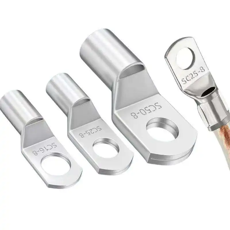
The correct lug is the intersection of two independent interfaces
Do not start with a hole size and assume the rest. Record the cable side and equipment side separately, then approve only the exact manufacturer part number, current drawing and tooling instructions that satisfy both.
What must enter the barrel?
- Nominal area: 16 mm²
- Copper grade or other documented conductor material
- Solid, stranded, flexible or other declared construction
- Round, compacted or sector shape
- Bare-conductor dimensions and applicable standard
- Insulation OD for stripping, entry and cable approach
Exact part + exact drawing + exact tool system
Approval exists at the complete-assembly level—not in the text “16 mm² M8 lug” by itself.
What must the palm meet?
- Nominal M6, M8 or M10 stud callout
- Actual stud and published lug-hole dimensions
- Palm width, length, thickness and reach
- Contact-surface and anti-rotation needs
- Washer, nut, cover and barrier envelope
- Equipment-maker connection instructions
This guide uses M6, M8 and M10 nominal stud interfaces. Manufacturer examples below show published clearance-hole diameters such as 6.4, 8.3, 8.4 or 10.5 mm. Those values are evidence for the named parts only; they do not create a universal hole table.
“16 mm² copper tube lug, M8” still leaves critical fields open
Use the phrase as a search starting point, not as a purchase specification. The receiving team must be able to compare the delivered item with controlled evidence.
| Term | It normally identifies | It does not establish | Evidence to request |
|---|---|---|---|
| 16 mm² | Nominal conductor cross-sectional area. | Barrel bore, conductor class, insulation range, current rating or completed-joint temperature performance. | Exact conductor datasheet plus lug conductor scope and barrel drawing. |
| Copper | A broad base-material family. | Exact material specification, temper, plating, surface condition or suitability for every copper or aluminium interface. | Part datasheet, material declaration and interface instructions. |
| Tube lug | A tubular compression-connector form. | One standard, one palm style, one inspection feature, one barrel geometry or one approval route. | Manufacturer family, part number, applicable standard and current drawing. |
| M6 / M8 / M10 | A nominal equipment-stud interface. | Literal hole diameter, palm width, palm length, edge distance, washer fit or terminal-cover clearance. | Equipment connection drawing and exact lug dimensions. |
| Tinned | A declared surface treatment when specified. | Coating thickness, process, corrosion performance or compatibility with every terminal surface. | Exact product declaration and project/environment requirement. |
| Certified / compliant | A claim that may relate to a named standard or program. | Acceptance of every catalog suffix, cable class, tool, end product or installation condition. | Certificate/listing scope, part identity, conditions and markings. |
A logo or standard number is not a substitute for scope. Preserve the exact order code, revision and referenced evidence in the approved supplier record.
M6, M8 and M10 are three different equipment interfaces
The conductor side may remain 16 mm² while the palm changes substantially. Choose the nominal interface shown by the equipment maker, then verify the complete palm envelope against the connection point.
M6
Confirm the equipment actually calls for an M6 connection and that the selected part's published hole clears the real stud without improvised modification.
- Check: hole diameter, palm width and contact area.
- Check: washer and nut seating within the palm.
- Check: barrel approach, bend radius and cover clearance.
- Reject: a larger palm that interferes with barriers or adjacent phases.
M8
Do not equate “M8” with an 8.0 mm hole. Current manufacturer examples in this guide publish 8.3 or 8.4 mm for named parts.
- Check: the actual drawing rather than a reseller label.
- Check: usable palm reach and edge distance.
- Check: flat seating against the equipment contact surface.
- Reject: forced fit, off-axis seating or unsupported washer contact.
M10
A larger nominal stud often comes with a different palm width and length. That may change terminal spacing, cover fit and cable approach even though the barrel remains 16 mm².
- Check: palm envelope against adjacent metalwork.
- Check: full contact, hardware stack and anti-rotation needs.
- Check: whether the equipment maker permits this lug construction.
- Reject: drilling or re-boring an M6/M8 palm to make it fit.
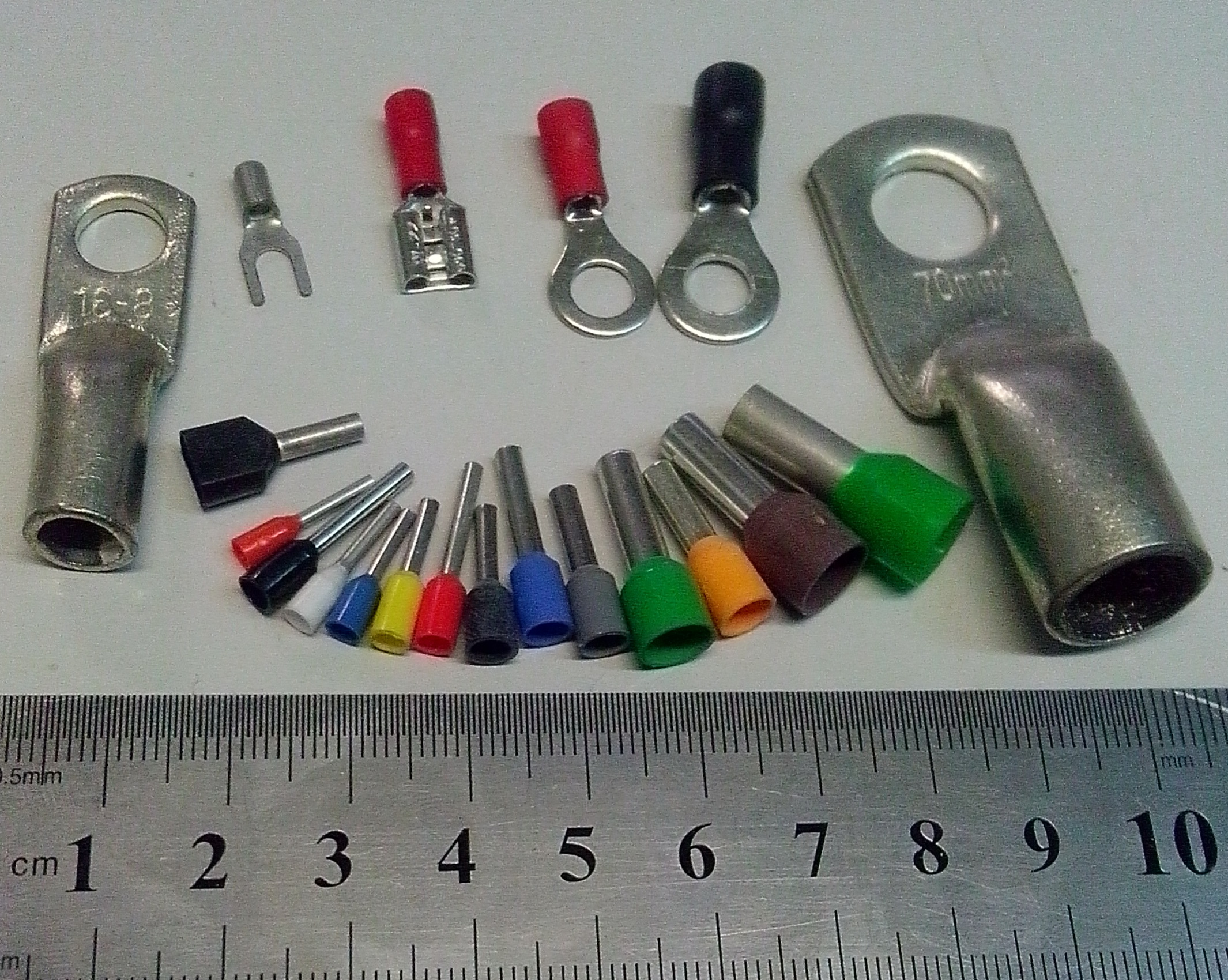

The nominal callout stays familiar; the actual geometry changes by part
The two current families below demonstrate why purchasers should control an exact manufacturer part and drawing. They are examples—not a cross-reference and not a universal dimensional standard.
| Part | Declared conductor scope | Nominal interface | Published hole ØD | Palm width B | Overall length L |
|---|---|---|---|---|---|
| A3-M6 | 16 mm²; Cembre labels the family for “flexible” and “low stranded” copper conductors | M6 | 6.4 mm | 11.5 mm | 29.5 mm |
| A3-M8 | Same named family scope; confirm the exact instruction and conductor | M8 | 8.4 mm | 15.0 mm | 33.5 mm |
| A3-M10 | Same named family scope; confirm the exact instruction and conductor | M10 | 10.5 mm | 18.0 mm | 37.5 mm |
Source: Cembre A-M family. The current page also states annealed electrolytic copper, tin plating, inspection hole, single-hole palm and a cULus claim for the family. Treat each as exact-family evidence and request the applicable certificate, markings and conditions.
| Part | Declared conductor scope | Nominal interface | Published hole d2 | Palm width b | Overall length l |
|---|---|---|---|---|---|
| 3R6 | EN 60228 Class 2 multistranded round and round-pressed sector conductors | M6 | 6.4 mm | 12 mm | 27 mm |
| 3R8 | Same normal declared scope; fine-stranded use is conditional on named ID tools | M8 | 8.3 mm | 15 mm | 29 mm |
| 3R10 | Same normal declared scope; confirm the exact connector/tool combination | M10 | 10.5 mm | 17 mm | 31 mm |
Source: Klauke tubular cable lugs, standard type. The family page states copper to EN 13600 with electroplated tin. Do not broaden its fine-stranded condition to every tool or every 3R application.
Cembre A3-M8 and Klauke 3R8 both describe 16 mm² / M8 products, but their published hole, width, length, conductor language, material declaration and tooling systems are not identical. A valid cross-reference compares the complete evidence set, not only “16 / M8 / tinned.”
A palm can clear the stud and still fail the assembly fit
Review the full drawing in the orientation used by the equipment. Terminal covers, barriers, adjacent lugs and cable bend space can make width, reach and barrel angle as decisive as the clearance hole.
Palm width and edge distance: the washer and nut need a supported seating area, while the palm must remain inside the equipment's phase-to-phase and phase-to-ground envelope.
Palm length and reach: the barrel should not collide with a barrier, cover, busbar step or neighboring termination. Verify the cable's permitted approach and bend radius using the cable data.
Palm thickness and contact surface: these affect the joint stack and hardware engagement. The equipment maker—not a generic lug article—controls the mounting and tightening method.
Barrel construction: inner/outer dimensions, entry chamfer, length, inspection feature and seam or tube construction affect conductor insertion and the qualified compression system.
- Measure the real interface: stud, available landing area, hardware stack, barriers and cover.
- Compare the controlled drawing: hole, width, length, thickness, barrel position and tolerances.
- Model the cable route: insulation OD, accessories, bend radius and strain control.
- Reject field modification: do not drill or re-bore the palm. A proposed change needs formal connector/equipment-maker approval and project requalification; otherwise choose a correct part.
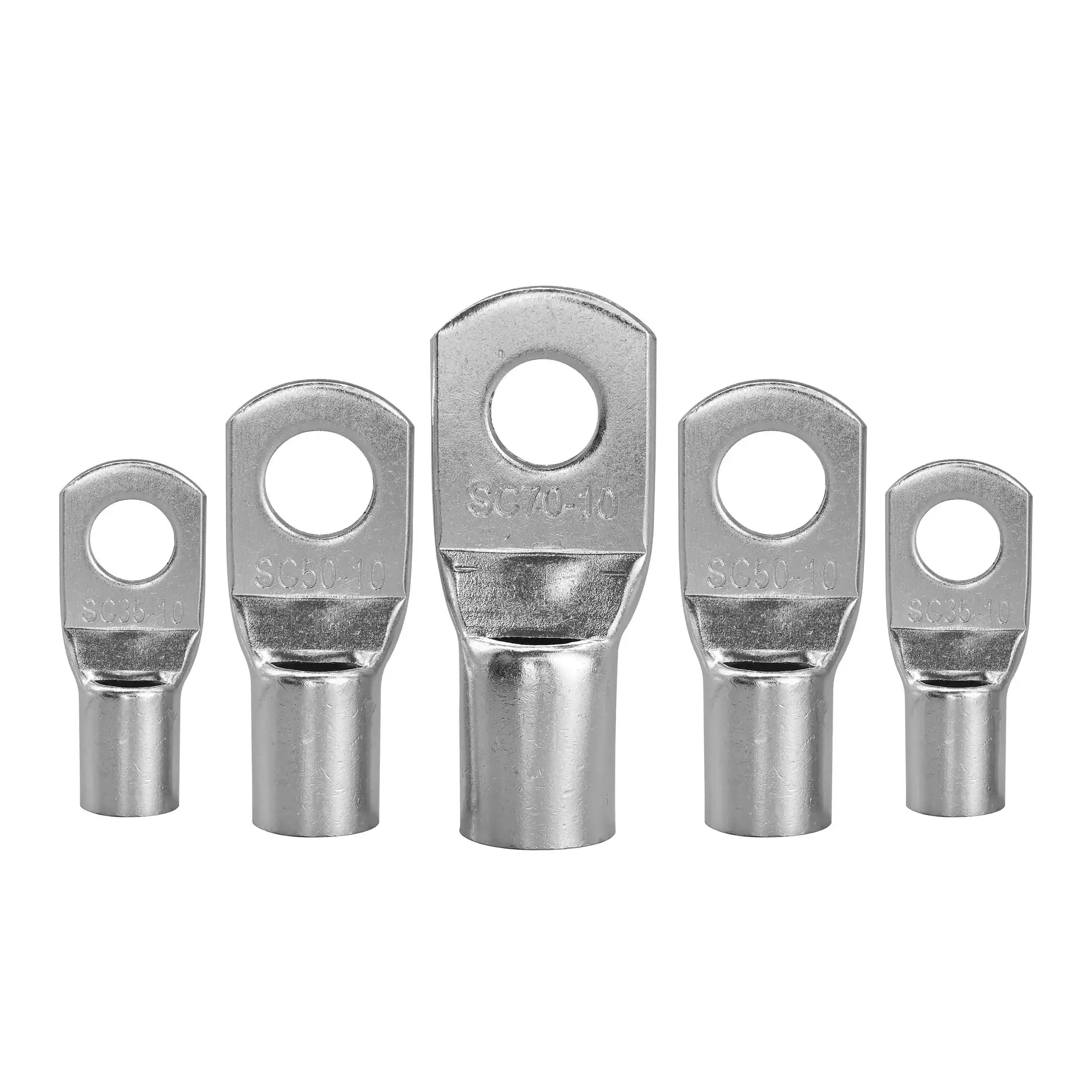
No standard number turns “16 mm²” into a universal lug rating
Each source answers a different question. Preserve those scopes instead of combining them into an unsupported current, temperature, tool or installation claim.
IEC 60228:2023
Defines nominal conductor areas and construction/resistance requirements. It does not rate a lug, bolted interface or completed circuit.
DIN 46235:1983-07
The current public record identifies compression cable lugs, cover-plate type, for copper conductors. The designation does not supply universal ampacity or installation data.
IEC 61238-1-1:2018
Covers stated type tests for compression and mechanical power-cable connectors within its scope. It is not an ampacity lookup table.
ANSI/UL 486A-486B
Defines scope and conditions for named connector/conductor combinations. A standard reference does not prove every conductor class or catalog suffix is accepted.
ANSI/UL 1976
Crimping tools are evaluated for identified connecting-device ratings and uses. Tool acceptance remains linked to the specified connector system.
Project and equipment data
Cable ampacity, enclosure temperature, grouping, equipment rating, hardware and installation rules complete the decision. Record all of them separately.
If a certificate, listing or test report is required, request the exact part identity, conductor scope, tool system and conditions—not just a standards logo.
The same nominal area can arrive in different conductor constructions
Strand count, strand diameter, compaction and shape change how copper occupies a barrel and responds to compression. Use the manufacturer’s declared conductor scope rather than an informal “flexible fits everything” rule.

Begin with the cable datasheet: manufacturer, complete order code, nominal area, conductor material, declared class/construction, strand arrangement, shape and applicable standard. If the lug supplier uses its own terms such as “flexible,” keep that wording and obtain the conversion evidence; do not silently map it to an IEC class.
Separate the bare-conductor diameter from the insulation outside diameter. The first affects barrel fit and strand consolidation. The second affects strip preparation, sealing accessories, cable entry, bend radius and physical approach.
Fine-stranded conductors may require a dedicated connector or a specifically qualified tool/profile. The current Klauke page, for example, states normal Class 2 scope and makes fine-stranded use conditional on named ID tools. That condition cannot be generalized to other tools, products or brands.
- Do not “size up” by guess: a loose barrel is not corrected by an improvised extra crimp.
- Do not trim strands: every strand belongs to the designed conductor section.
- Do not borrow preparation data: strip length and brush/cleaning instructions are connector-system values.
- Do not mix evidence: a conductor certificate, lug certificate and tool report must describe a compatible combination.
Pass six gates before a 16 mm² lug enters the approved BOM
This is a procurement and engineering workflow, not an energized-work procedure. A failed gate is a stop condition, not a reason to improvise.
Capture the equipment interface
Record the equipment maker, terminal identifier, nominal stud, actual geometry, contact surface, hardware, cover/barrier envelope and permitted cable approach. Keep the controlling drawing revision.
STOP IF THE EQUIPMENT INTERFACE IS UNKNOWNIdentify the cable completely
Record the exact cable order code, 16 mm² nominal area, material, construction/class, shape, bare-conductor data, insulation OD and applicable standard. Resolve conflicting datasheets before selection.
STOP IF ONLY “16 MM² CABLE” IS KNOWNChoose a compatible lug family
Compare the declared conductor scope, material/plating, barrel construction, environmental and equipment-interface requirements, approvals and project standard. Do not begin with a reseller photograph.
STOP IF FAMILY SCOPE IS INFERREDSelect the exact palm variant
Choose M6, M8 or M10 from the equipment requirement, then compare the part drawing for hole diameter, palm width/length/thickness, reach, contact area and tolerances.
STOP IF A FIELD MODIFICATION IS PROPOSEDQualify the connector/tool system
Obtain the named tool, die/profile, tool setting, strip/preparation data, crimp locations/count, calibration/service requirements and acceptance inspection for the exact part and conductor.
STOP IF THE TOOL IS “CLOSE ENOUGH”Lock evidence into purchasing
Put the manufacturer part number, drawing revision, conductor scope, approved tooling reference, certificates, markings, packaging identity and change-notification requirement into the PO and receiving plan.
STOP IF EQUIVALENTS ARE UNCONTROLLEDThere is no generic “16 mm² die” or universal crimp count
Connector, conductor, tool, die/profile and instructions form one qualified system. Perform conductor preparation and compression only in a deenergized work process under the applicable safety procedure and exact manufacturer instructions.
The current Cembre instruction sheet demonstrates the correct evidence pattern: choose the proper connector, named tool/die and stated number of crimps from its system table. The same document supplies part-specific preparation data and warns that crimping is for deenergized conductors.
That evidence does not authorize applying Cembre values to another brand, tool, lug family or conductor construction. Likewise, a general tool standard does not establish that a tool/die combination is approved for every connector within its mechanical capacity.
- Identity: connector part number and cable construction match the instruction.
- Tool: exact tool model, service state and calibration/inspection status are acceptable.
- Die/profile: exact die set, index or intelligent-die condition is documented.
- Preparation: stripping, cleaning, strand control and insertion follow the named procedure.
- Compression: location, sequence and count follow the exact system—not a photograph.
- Inspection: markings, profile and any dimensional or pull/test criteria come from controlled documents.

Inspect what was delivered against the approved evidence set
Receiving inspection should detect wrong interfaces, wrong families and uncontrolled substitutions before parts reach the panel floor.
| Finding | Why it matters | Evidence to compare | Disposition |
|---|---|---|---|
| Correct “16 mm²” marking, wrong M interface | The barrel may suit the cable while the palm cannot fit the equipment connection. | PO line, part marking, package label and drawing hole/palm dimensions. | Quarantine the lot; do not drill, re-bore or force the palm. |
| Right nominal interface, unfamiliar palm geometry | A wider, longer or thicker palm can collide with barriers, covers or adjacent parts. | Approved drawing revision and equipment envelope. | Hold for engineering comparison and formal approval. |
| Supplier changed suffix or family | Conductor scope, material, plating, approvals or tooling can change with the suffix. | Approved manufacturer part number, change notice and certificate scope. | Treat as a substitution; do not accept by visual similarity. |
| Marking or packaging is incomplete | Traceability to the exact part, lot and controlled evidence may be lost. | Specified markings, packaging identity, certificate and lot record. | Quarantine until supplier provides verifiable traceability. |
| Tooling sheet does not name the received part | A mechanically possible crimp is not automatically a qualified connection. | Current connector/tool compatibility table and instruction revision. | Stop release; obtain exact manufacturer confirmation. |
| Surface or geometry is visibly damaged | Contact, insertion or compression behavior may be affected. | Supplier acceptance criteria, drawing and damage limits. | Segregate and disposition through the quality process. |

Record supplier, manufacturer, exact part number, nominal conductor scope, nominal stud interface, drawing revision, lot/package identity, certificate/listing reference where required, visual/dimensional inspection result, quantity accepted and any deviation approval. Photograph packaging and markings when project traceability calls for it.
Send a buildable 16 mm² lug RFQ—not a three-word description
Attach the equipment and cable evidence. SENTOP can then review the barrel, palm, documentation and supply requirements against one controlled request.
Eight answers to prevent the most common selection errors
Is an M6 lug interchangeable with an M8 or M10 lug?
No. The nominal stud interface, published hole diameter and wider palm geometry can differ. Select the exact interface required by the equipment and verify the complete part drawing; do not drill, re-bore or force a different palm.
Does 16 mm² tell me the lug current rating?
No. It is a nominal conductor cross-sectional area. The acceptable current and temperature depend on the exact connector/conductor system, equipment terminals, cable installation, enclosure, ambient conditions and governing design rules.
Is an M8 lug hole exactly 8.0 mm?
Not necessarily. M8 is a nominal stud callout. The named examples on this page publish 8.3 mm or 8.4 mm holes, while other parts may differ. Use the current manufacturer drawing for the exact part.
Can I drill an M6 palm to fit an M8 stud?
Do not modify the palm as a field workaround. Drilling can change contact area, edge distance, plating and qualification. A proposed modification requires formal connector- and equipment-maker approval plus project requalification; otherwise select the correct M8 part.
Do flexible conductors need a different 16 mm² lug?
They may. “Flexible” is not a universal compatibility statement. Obtain the cable construction/class and the lug manufacturer's declared scope. Fine-stranded use can require a dedicated connector or named tool/profile combination.
Does a copper lug suit every copper or aluminium terminal?
No. Base material alone does not establish interface compatibility. Confirm lug material and plating, equipment terminal material/finish, environmental conditions, joint hardware and both manufacturers' connection instructions.
Which standard should I request for a 16 mm² tube lug?
Request the standard and approval route required by the project and market, then verify exact scope. IEC 60228 concerns conductors; DIN 46235 describes a product form; IEC 61238-1-1 concerns stated connector type tests; UL 486A-486B and UL 1976 have their own connector and tool scopes.
What should I inspect when 16 mm² lugs arrive?
Check supplier and manufacturer identity, exact part number, package and lot traceability, markings, nominal conductor and stud-interface scope, drawing dimensions, surface/geometry condition, required documents and tooling compatibility. Quarantine any uncontrolled substitution or discrepancy.
Use the current source for the question it actually answers
- IEC 60228:2023, Edition 4: conductor nominal areas, construction and resistance requirements. IEC Webstore record.
- DIN 46235:1983-07: cable lugs for compression connections, cover-plate type, for copper conductors; public record currently marked current. DIN Media record.
- IEC 61238-1-1:2018: type tests for compression and mechanical connectors for power cables within the stated scope. IEC Webstore record.
- ANSI/UL 486A-486B, Fourth Edition (14 March 2025): connector/conductor scope and conditions. UL Standards record.
- ANSI/UL 1976, First Edition (24 June 2024): crimping tools evaluated for identified connecting-device uses. UL Standards record.
- Cembre A-M family: exact A3-M6, A3-M8 and A3-M10 published dimensions and family declarations. Cembre family page and manufacturer installation sheet.
- Klauke standard-type tubular copper lugs: exact 3R6, 3R8 and 3R10 dimensions, material and conductor/tool conditions. Klauke family page.
Source status and public records checked 25 August 2026. Always obtain the current manufacturer drawing, instruction and certificate/listing scope for the exact order code before release.
Need SENTOP to compare a 16 mm² cable with an M6, M8 or M10 interface?
Send the cable datasheet, equipment termination drawing, market/standard requirements, intended environment and documentation needs. The review can then focus on an exact, traceable connector and tool system.