A three phase distribution box controls and guards electricity in three-phase power systems. This device makes sure power goes to big machines safely and quickly. Many factories and businesses use these boxes to run things like motors, air compressors, and heaters. Big buildings with many floors also need them for steady power. Some houses that use a lot of power may have a three phase distribution box to help both normal and high-power appliances.
Key Takeaways
- A three phase distribution box helps control and share electricity. It sends power to big machines and buildings. This keeps the power steady and safe.
- These boxes use breakers and fuses to protect circuits. They stop problems like overloads, short circuits, and shocks before they start.
- Balancing the power load on all three phases is important. It helps machines work well and saves energy. This also stops damage and saves money on repairs.
- Picking the right box means you must check power needs, voltage, and safety ratings. You should always get a licensed electrician to install it.
- Portable and strong three phase boxes are good for temporary jobs. They work well at events and construction sites. They give safe and easy power anywhere.
Three Phase Distribution Box Overview

Definition and Purpose
A three phase distribution box is like a main station for electricity in places that use three-phase power. It sends power from the main source to different circuits. Each machine or area gets the right amount of electricity. The box keeps circuits safe by using things like circuit breakers and fuses.
A three phase distribution box helps keep people safe. It hides wires and lets you control many circuits from one spot. Electricians can change these boxes to fit what factories, big buildings, or even temporary places like construction sites need.
The main jobs of a three phase distribution box are:
- Sending power to many circuits for better control.
- Keeping circuits safe from short circuits and too much power.
- Making things safer by hiding wires and putting controls together.
- Helping save energy and making circuits work better.
- Letting people change the box for special needs.
- Having tools to measure, control, and signal.
- Making sure power is safe and works well in different places.
Single vs. Three Phase
Single phase and three phase distribution boxes are different in many ways. The table below shows the main differences:
| Aspect | Single-Phase Distribution Box | Three-Phase Distribution Box |
|---|---|---|
| Number of Conductors | One AC wave (single conductor) | Three AC waves offset by 120 degrees (three conductors + neutral) |
| Power Output Capacity | Lower capacity, good for small homes | About 180% more power, good for big factories |
| Efficiency | Not as efficient, can have power problems | More efficient, lighter wires, better power |
| Reliability | More shaking and less steady | Less shaking, more steady and reliable |
| Typical Applications | Home devices, small lights, low power things | Factory machines, HVAC, tall buildings, data centers, farms |
| Voltage Levels | Usually 120/240V | Usually 120/208V or 277/480V, can be set for higher volts |
| Maintenance & Cost | Cheaper at first, but costs more to fix later | Costs more at first, but cheaper to keep running |
| Power Delivery | Power goes up and down, not always steady | Power stays steady because of the three phases |
| Wiring Complexity | Easier wiring, fewer parts | More complex wiring, but uses less metal for each kW |
| Suitability | Best for homes or small shops | Needed for big buildings, factories, and important places |
Three phase distribution boxes work better and are more steady, especially for big jobs. They can handle a lot of power and keep it balanced. This makes them great for factories, offices, and places that need strong, steady electricity. Single phase boxes are fine for homes and small shops, but they can’t do as much as a three phase box in tough places.
Key Functions
Power Distribution
A three phase distribution box helps send electricity to many places. It connects to the main power and splits it into smaller circuits. Each circuit can power a different room or machine.
- These boxes, sometimes called spider boxes, let you connect many things to one power source.
- They help send power to lights, sound systems, food trucks, and radios.
- Each circuit has overcurrent protection to keep things safe.
- Distribution panels control power from generators to event areas using circuit breakers.
- Weatherproof connectors and outdoor cables keep things safe outside.
- Good planning stops overloads and voltage drops, so every device gets steady power.
A three phase distribution box works for both permanent and temporary setups. Event planners, factories, and building sites use these boxes to keep things running well.
Tip: Always check voltage and current before adding new equipment. The right box keeps power safe and steady.
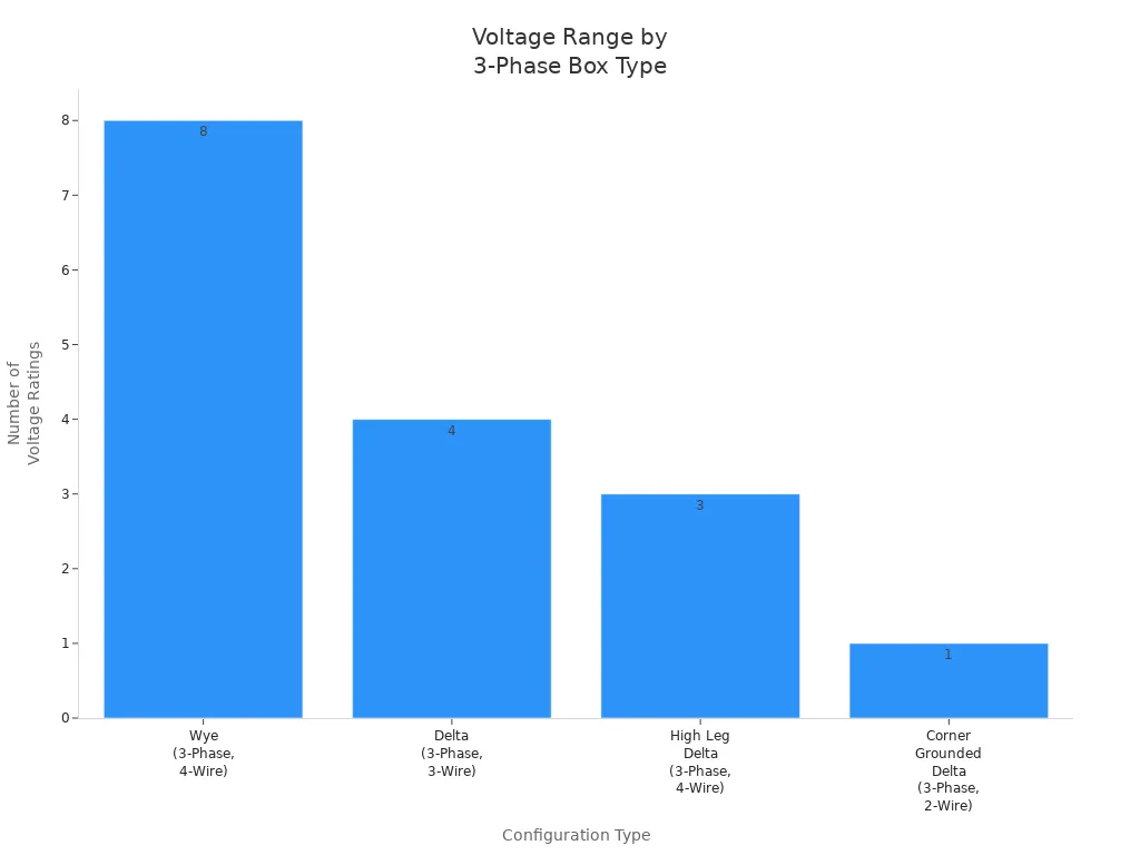
The tables below show common voltage ratings for three phase distribution boxes in factories:
| System Description | Line-to-Neutral Voltage (V) | Line-to-Line Voltage (V) | Typical Usage |
|---|---|---|---|
| 3-Phase, 4-Wire Wye | 120V, 277V, 347V | 208V, 480V, 600V | Commercial lighting, HVAC, industrial equipment |
| 3-Phase, 3-Wire Delta | N/A | 240V, 400V, 480V, 600V | Industrial motor loads, utility power distribution |
| 3-Phase, 4-Wire Delta (High Leg) | 120V, 208V | 240V | Older manufacturing facilities with mixed loads |
| 3-Phase, 2-Wire Corner Grounded Delta | N/A | 480V | Cost-saving wiring method, less common today |
| Configuration Type | Typical Voltage Ratings (Volts) | Wiring Configuration | Notes |
|---|---|---|---|
| Wye (3-Phase, 4-Wire) | 208V, 240V, 277V, 347V, 400V, 415V, 480V, 600V | 3 Hot wires + Neutral + Ground | Common in industrial and commercial panels |
| Delta (3-Phase, 3-Wire) | 240V, 400V, 480V, 600V | 3 Hot wires + Ground | Used for utility power distribution and large motors |
| High Leg Delta (3-Phase, 4-Wire) | 120V, 208V, 240V | 3 Hot wires + Neutral + Ground | Older manufacturing facilities, includes a ‘high leg’ |
| Corner Grounded Delta (3-Phase, 2-Wire) | 480V | 2 Hot wires + Ground | Used to reduce wiring costs, less common today |
Circuit Protection
A three phase distribution box keeps people and equipment safe from electrical problems. It uses different protection devices to stop trouble before it happens. These devices watch for too much power, short circuits, and other issues.
| Protection Mechanism | Function / Protection Provided |
|---|---|
| Thermal Overload Relays | Protect motors from overheating and phase loss |
| Current Monitoring Relays | Detect under- and over-current conditions |
| Voltage Monitoring Relays | Monitor voltage problems |
| Power Monitoring Relays | Watch power factor and total power (kW) |
| Thermistor Monitoring Relays | Protect equipment from getting too hot |
| Surge Protectors and Filters | Block surges and electrical noise |
| Load Switches | Allow local motor isolation and manual disconnect |
| Circuit Breakers (MCCBs, MPCBs, MCPs) | Stop power during overcurrent, short-circuit, or thermal events |
| Fused and Non-fused Disconnect Switches | Provide isolation and manual switching |
| Fuse Blocks | Hold fuses for circuit protection |
| Electronic Circuit Protection Modules | Protect secondary circuits from short circuit or overload |
Circuit breakers shut off power if there is too much current or a short circuit. Residual current circuit breakers (RCCBs) find current problems and stop shocks. Isolators let workers turn off power safely for repairs. Grounding bus bars give extra current a safe path, stopping shocks and fires. Surge protectors guard against sudden power spikes.
Note: Check and fix protection devices often to keep them working. Loose or broken wires can cause problems, so always check connections.
Load Balancing
Load balancing helps the electrical system stay safe and work well. A three phase distribution box spreads power evenly across all three phases. This stops one phase from getting too much power.
- Electricians plug devices into outlets on different phase pairs (L1/L2, L2/L3, L3/L1) to share the load.
- Some boxes use groups of outlets, repeating phase assignments to make balancing easier.
- This lets devices be plugged in close to where they are used, which cuts down on cable mess.
- Balanced loads make the system more reliable and help save energy.
- Bad load balancing can cause voltage drops, overheating, and tripped breakers.
- Motors and other machines may sound strange or break faster if loads are not balanced.
- Lights may flicker, costs can go up, and safety problems can happen if loads are not even.
- Keeping loads balanced protects equipment and helps the system last longer.
⚡ Pro Tip: Always plan where to put high-power devices to keep loads even. This helps avoid expensive repairs and keeps things running.
Three Phase Distribution Box Components
Busbars
Busbars are the main metal strips inside the box. They carry a lot of electricity to different circuits. These bars connect the power coming in to all the breakers and fuses.
- Busbars give one main path for strong currents and high voltage. This helps electricity move fast and easy.
- They can handle big problems, like too much current, and keep things safe.
- Labels on busbars help workers find problems quickly.
- Sensors can check heat and shaking, so workers know if something is wrong.
- Workers can check busbars from far away, so they do not touch live parts.
- Some busbars are made to be changed or upgraded easily.
- Newer busbars have safety features, like stopping too much current.
Copper and aluminum are the most used materials for busbars. The table below shows how they are different:
| Property | Copper Busbar | Aluminum Busbar |
|---|---|---|
| Electrical Conductivity | High (~58 MS/m) | Moderate (~37 MS/m) |
| Weight | Heavy | Light |
| Cost | Expensive | Cheaper |
| Mechanical Strength | Strong | Softer |
| Corrosion Resistance | Good | Average, needs treatment |
| Current Capacity | High | Needs larger size for same current |
Breakers and Fuses
Breakers and fuses stop too much current or short circuits. They turn off the power if something goes wrong. This keeps people and machines safe. Three phase distribution boxes use different kinds of breakers:
| Breaker Type | Description | Typical Application |
|---|---|---|
| 3P (Three-pole) | Three terminals, for three-phase loads | Pure three-phase equipment |
| 3PN (Three-pole + Neutral) | Four terminals, handles mixed loads | Mixed three-phase and single-phase loads |
| 4P (Four-pole) | Four terminals, interrupts neutral too | Systems needing neutral interruption |
Breakers can trip in different ways. Type C breakers are good for most jobs. Type D breakers work better for motors and machines that need more power to start.
Enclosure and Safety
The enclosure is the outside box that keeps everything safe. It protects the parts from dust, water, and getting broken. In risky places, special enclosures stop sparks or fire from getting out. These boxes are made from strong metals like stainless steel or cast aluminum. Gaskets seal the box to keep out gas and dust. Some enclosures keep the air inside safe or stop sparks from starting. If a box has ATEX or UL marks, it meets tough safety rules. Good cooling stops the box from getting too hot. Checking seals and gaskets often keeps the box safe for a long time.
Safety Tip: Always look for damage on the box before you work. Taking care of the box helps stop accidents.
Applications and Benefits
Industrial and Commercial Use
Many businesses and factories use three phase distribution boxes for safe power. These boxes help in many ways:
- Construction and mining sites use them for big machines. This makes work safer and faster.
- Disaster teams use them when there are power problems. They give steady power during emergencies.
- Event planners use them at concerts and sports games. They help send power to lights and sound.
A three phase distribution box helps things run well in tough places. It powers big machines, lights, and setups that are not permanent.
Portable and Specialized Types
Some three phase distribution boxes are made to be moved around. These special boxes are good for short-term jobs. The table below shows what makes them different:
| Feature Category | Details |
|---|---|
| Standards Compliance | EN 60439-4, IEC 60529 |
| Protection Rating | Waterproof and shockproof, up to IP67 |
| Material | Polycarbonate resin (PC), light, strong, and smooth |
| Design | Stackable modular design, space-saving, daisy chaining |
| Portability | Compact size, easy-to-carry handle |
| Operating Temperature | -20℃ to +75℃ |
| Safety Features | Circuit breakers (MCB, RCD, RCCB, RCBO) for overload protection |
| Assembly | Quick assembly, safe connections, reusable components |
| Customization | CNC perforation, pre-wiring, OEM/ODM services |
| Applications | Construction, events, industrial, military, marine, railway, airports |
Portable boxes can be changed to fit different needs. Some have twist-lock or camlock connectors. Many have covers to keep out rain and dust. They are safe to use outside and have strong safety parts. These boxes follow rules like NEC, OSHA, and UL.
Note: Portable three phase distribution boxes make it safer and easier to set up power for short times.
Advantages
A three phase distribution box has many good points over other ways to share power:
- It works better and wastes less power.
- It spreads power evenly, so machines last longer.
- It gives enough power for big machines and elevators.
- It keeps power steady and stops problems like flickering lights.
- It makes things safer by lowering fire and shock risks.
- It helps motors last longer by stopping them from getting too hot.
- It can be used in many places, like offices and charging stations.
- It works with both Delta and WYE setups for more choices.
These good points make three phase distribution boxes the best pick for today’s factories and big buildings.
Selection and Installation
Capacity and Voltage
Picking the right three phase distribution box starts with knowing how much power is needed. Electricians add up the wattage of all machines and devices. They check what voltage each piece of equipment needs. Most factories use 208V, 400V, or 480V systems. The box must handle the biggest current expected. Choosing a box with extra space helps stop overloads later.
Tip: Always pick a distribution box that can handle more current than you need now. This lets you add more equipment later and keeps things safe.
A table can help you look at your choices:
| Factor | What to Check |
|---|---|
| Total Load | Add up all equipment wattages |
| Voltage Rating | Match with site supply (e.g., 400V) |
| Number of Circuits | Count all needed circuits |
| Expansion Room | Allow for future equipment |
Compliance and Safety
Safety and following the rules are important for every setup. Electricians must follow local codes like NEC or IEC standards. The three phase distribution box should have safety marks like UL or CE. These marks show the box passed safety checks. The outside box must have the right IP rating for where it will be used. In wet or dusty places, a higher IP rating keeps the inside parts safe.
Note: Only use boxes with clear labels and safety marks. This helps inspectors and keeps workers safe.
Installation Tips
Good installation makes sure the system works and stays safe. Electricians put the box on a strong wall or frame. They use the right wire size for each circuit. All wires must be tight to stop overheating. Grounding the box helps stop electric shocks. Workers should never work on the box when it is turned on.
- Plan where everything goes before starting.
- Label all circuits so fixing problems is easy.
- Test the system before turning on the main power.
⚡ Always hire a trained electrician to install the box. This lowers risks and makes sure the system follows all rules.
A three phase distribution box helps manage power safely and easily.
- It spreads out power, keeps machines safe, and works with Delta and Wye setups.
- Factories use these boxes for motors, HVAC, and data centers. Big houses get steady power and quick charging from them.
- Checking and installing the box the right way makes it last longer and break less often.
If things are tricky, ask an expert for help. Knowing how power is shared keeps everything safe and working well.
Choose ONESTOP distribution box: With over 20 years of manufacturing experience, international certification assurance, and excellent quality, we help you comprehensively improve circuit safety protection.


FAQ
What is the main difference between a three phase and a single phase distribution box?
A three phase distribution box can handle more power. It is used for bigger machines and equipment. It has three wires for electricity. A single phase box only has one wire. Factories and tall buildings use three phase boxes for steady power.
Can a three phase distribution box be used outdoors?
Yes, some three phase distribution boxes are made for outside use. These boxes have covers that keep out rain and dust. They also protect against bumps and hits. Always look at the IP rating to make sure it is safe for outdoors.
How often should a three phase distribution box be inspected?
Electricians should check the box at least once every year. Regular checks help find loose wires or broken parts. They also help spot overheating early. Finding problems soon keeps everyone safe.
What safety features do three phase distribution boxes include?
Most boxes have circuit breakers and fuses inside. They also have grounding bars for extra safety. Some boxes have surge protectors and heat sensors too. These parts help keep people and machines safe from electrical problems.
Who should install a three phase distribution box?
Only a licensed electrician should put in or fix a three phase distribution box. This makes sure the box is safe and works the right way.
The following information may be of interest to you
Single vs Three Phase MCCB: Key Differences
Comparing Single Phase Voltage and Three Phase Voltage
Choosing Between Single-Phase and Three-Phase Solar Inverters
Single Phase vs Three Phase Electricity: Which is Best for You?
Single Phase Distribution Box Definition and Main Parts