
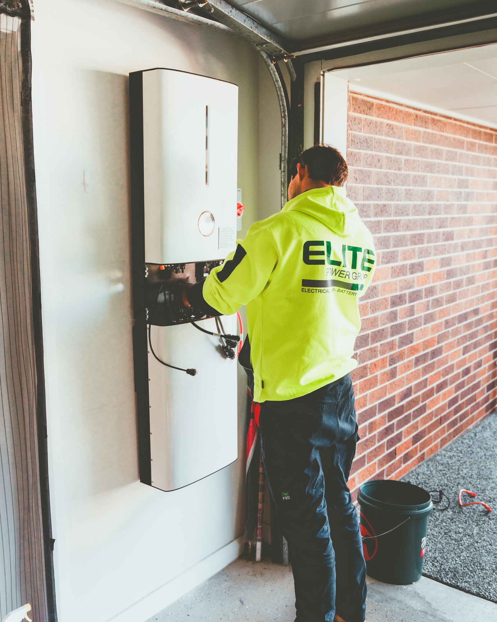
Single-Phase vs Three-Phase Solar Inverters: How to Choose
Choose from the approved AC connection outward—not from roof area or a generic kW cutoff. A single-phase inverter is the natural starting point for an approved single-phase point of interconnection (POI). A native three-phase inverter is the natural starting point when the approved POI and export strategy require three-phase output. The exact voltage, grid profile, export rules, DC design, and backup architecture still decide whether a model fits.
Start at the grid connection, not the roof
Pass these four gates before comparing price, efficiency, MPPT count, monitoring, or warranty. If one gate fails, a familiar inverter can still be wrong for the project.
What is the approved phase and full voltage system?
Record phase, line-to-line and line-to-neutral values where relevant, frequency, neutral/wire arrangement, and the exact POI. “240 V” or “400 V” alone is incomplete.
What may the system install and export?
Confirm utility or distribution network operator (DNO) approval, per-phase limits, imbalance rules, metering, fixed or dynamic export control, and required grid profile.
Does the inverter match both AC and PV DC?
Check output topology, kW/kVA, current, voltage range, power factor, listing, DC voltage/current, MPPT inputs, temperature derating, communications, and firmware region.
Is the goal grid-tied energy or outage support?
Backup needs more than a phase label. Define protected loads and phases, battery power and energy, intentional isolation, controls, neutral/grounding strategy, and generator interaction.
Single-phase or three-phase? The POI is the first gate
“Single phase” does not mean one conductor, and “three phase” does not mean automatically better. The inverter must use the exact listed AC arrangement for the site.
| Decision factor | Single-phase solar inverter | Three-phase solar inverter |
|---|---|---|
| Best starting point | An approved single-phase or split-phase POI whose voltage, export, and equipment limits fit the exact product. | An approved three-phase POI that calls for native three-phase injection across the stated grid configuration. |
| AC output | Produces one AC waveform and connects in the exact listed line-to-neutral, line-to-line, or split-phase arrangement. Do not infer conductor count from the label. | Produces a designed three-phase set for a stated voltage, frequency, sequence, and conductor arrangement. |
| Phase-balance effect | On a three-phase site, an approved L-N or L-L connection can create unequal per-phase current or export. The result depends on topology and utility rules. | Normally distributes its own intended output across three phases. It does not redistribute unrelated building loads or guarantee equal net flow. |
| Typical context | Common on homes and single-phase sites, but there is no universal roof-size or kW limit that defines the class. | Common on commercial, industrial, and three-phase sites, but project size alone does not make it the correct choice. |
| PV DC design | Phase does not define module count, string architecture, DC/AC ratio, MPPT count, shading behavior, optimizer use, or annual energy yield. Compare exact DC limits separately. | |
| Export control | Installed/nameplate capacity and permitted export are different. A non-export or limited-export setting needs an approved power control system, meter or CT placement, fail-safe behavior, and commissioning evidence. | |
| Battery and backup | Neither phase option guarantees outage operation. The complete listed system must support the required phases, loads, battery, isolation/transfer, controls, grounding, and operating sequence. | |
| Main risk | Assuming it can connect to any three-phase site or that one phase label describes its exact terminal arrangement. | Assuming it fits any “three-phase” voltage, fixes all load imbalance, or always yields more energy. |
Selection principle: use the approved interconnection design and the exact model data. Examples are not universal rules for every country, utility, voltage, inverter family, or firmware profile.
Phase is one link in the complete energy path
The PV array provides DC power. The inverter must accept that DC within its voltage, current, and maximum power point tracking (MPPT) limits, then produce AC that matches the approved POI. Utility controls and facility loads sit beyond the inverter.
Do not use one label to answer four questions. AC phase does not identify the PV string design, permitted grid export, annual yield, or outage capability. Each needs its own evidence.
This diagram is not a wiring, protection, grounding, metering, or commissioning plan. The approved one-line diagram and exact product instructions control the project.
A voltage number does not identify the connection
Record the complete service designation from authorized project documents. North American examples include 120/240 V split phase, 208Y/120 V three phase, and 480Y/277 V three phase. IEC-influenced markets commonly use designations such as 230/400 V. These are examples, not interchangeable product settings.
A single-phase inverter may connect line-to-neutral, line-to-line, or across a listed split-phase arrangement. A three-phase inverter must match the stated line voltage, frequency, phase sequence where relevant, neutral/wire arrangement, grounding system, and regional grid profile.
For a deeper explanation of line-to-line and line-to-neutral values, see SENTOP’s single-phase vs three-phase voltage reference.
S = V × IUse the RMS voltage across the inverter’s AC output terminals. Real power is P = V × I × PF.
S = √3 × VLL × ILReal power is P = √3 × VLL × IL × PF. Do not use this shortcut for an unknown or materially unbalanced system.
same S + same VLLOnly under those same conditions does balanced three phase use less current per line. Compare actual maximum output current.

These equations help compare apparent power and line current. They do not size conductors, breakers, buses, disconnects, grounding, or fault duty. The final design must use the exact maximum continuous output current, environmental derating, product instructions, adopted code, and approved calculations.
Compare the data sheet as an AC-and-DC system
Nominal kW is only one row. An inverter can be large enough on paper and still fail the grid, DC-input, environmental, or approval gate.
| Data-sheet field | What to verify | Why the buyer needs it |
|---|---|---|
| AC topology and grid | Single phase, split phase, or three phase; exact voltage range; frequency; conductor/neutral arrangement; country or utility grid profile. | This is the compatibility gate. Do not infer it from family name, cabinet shape, or maximum kW. |
| Rated and maximum AC output | Real power in W/kW, apparent power in VA/kVA, maximum continuous output current, and the conditions attached to each value. | Supports interconnection, panel, conductor, protection, and export review by the qualified project team. |
| Power factor and grid support | True power-factor range, reactive-power capability, volt-var/frequency functions, ride-through, and required regional settings. | Reactive-power duties and grid profiles can change available real-power output and approval requirements. |
| PV DC limits | Maximum DC voltage, startup and MPPT windows, input and short-circuit current limits, approved modules, and temperature assumptions. | Prevents cold-voltage overrun, poor startup, excessive current, or an array the inverter cannot accept. |
| MPPT and inputs | Independent trackers, input pairs, string rules, optimizer or module-electronics compatibility, and allocation by orientation or shade group. | Phase count does not reveal tracker count or how separately performing sub-arrays should be grouped. |
| Thermal and location limits | Ambient range, enclosure rating, cooling, mounting orientation, altitude, corrosion exposure, and product-specific derating curves. | Nameplate output may reduce in hot or constrained locations. An enclosure label does not prove every outdoor or corrosive application. |
| Export and communications | Compatible meter/CT, power control system (PCS), response and fail-safe behavior, monitoring, network needs, firmware ownership, and data retention. | Limited-export or non-export operation is a controlled system function, not a simple nameplate reduction. |
| Listing and evidence | Exact model/suffix, market, current certificate or listing, supported accessories, grid-code evidence, warranty, and change-control status. | Certification applies to the evaluated scope. It does not approve the entire site installation or every model in a family. |
Three phase does not create more sunlight
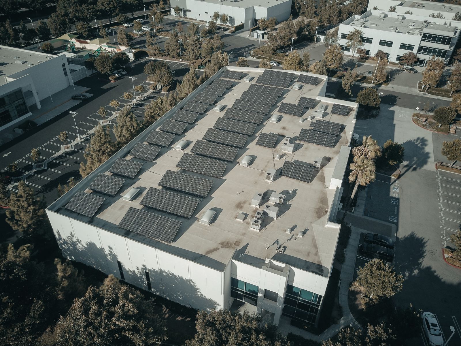
Annual production starts with irradiance, roof or ground geometry, module orientation, shading, temperature, soiling, availability, and the PV design. The inverter then converts available DC power within its voltage, current, thermal, grid, and export limits.
Shading or mismatch on one module can reduce the power available from a series string. The size of that loss depends on bypass diodes, string layout, MPPT allocation, module electronics, and operating conditions. This is an inverter-architecture and array-design question—not a phase rule.
Clipping, curtailment, or export limiting can also reduce delivered AC energy. A planned DC/AC ratio can still be sound, but it must come from site modelling and exact equipment limits rather than a universal oversizing percentage.
- Phase: how the inverter connects and exports AC.
- MPPT architecture: how different PV sub-arrays are tracked.
- DC/AC ratio: the relationship between installed PV DC capacity and inverter AC capability.
- Yield: the modeled energy result after resource, losses, limits, and availability.
Plan for per-phase flow, export control, and failure states
A native three-phase inverter normally injects a balanced three-phase output in its approved operating mode. The service can still be unbalanced because the building loads are not automatically redistributed.
Model more than normal operation
Check normal output, unequal site loads, reverse flow, voltage rise, curtailment, and what happens if one unit trips in a multi-inverter arrangement. A single-phase proposal on a three-phase site may connect L-N or L-L.
Do not assume phase netting
Revenue-meter treatment of import and export, per-phase reverse flow, and billing depends on the utility tariff and meter configuration. Confirm it rather than assuming all phases net in the owner’s favor.
Define the measured boundary
Document meter or CT location and direction, controller authority, communications, response time, loss-of-signal behavior, permitted fallback state, commissioning test, and retained evidence.
Inverter nameplate capacity, installed generation capacity, and permitted export capacity are different. Limiting export at the POI does not automatically reduce inverter, conductor, protective-device, bus, or fault-duty requirements, and it does not remove the interconnection process.
A phase label is not a backup promise
A traditional grid-following inverter uses an existing grid reference and is expected to cease normal grid export after loss of that reference. Grid-forming capability can be a required part of an islanded system, but it is not sufficient by itself.
The complete approved architecture must coordinate intentional islanding or transfer equipment, grid disconnection, controls, a compatible battery or explicitly supported PV-only mode, protected loads, neutral and grounding behavior, load shedding, black start where required, generator interaction, and return-to-grid logic.
A three-phase grid-tied inverter is not automatically a three-phase backup source. A single-phase protected-load panel on a three-phase facility can also be suitable only when its voltage, transfer, grounding, load, and approval conditions are resolved.

Use an eight-step review before the purchase order
The sequence prevents a team from optimizing price or nominal efficiency before it knows whether the inverter can legally and electrically connect.
Confirm the POI
Record phase, complete voltage designation, frequency, conductor and neutral arrangement, grounding system, service role, source or transformer, and available capacity.
Confirm permission
Identify the utility or DNO, authority having jurisdiction (AHJ), adopted grid rules, permitted topology, export limit, imbalance rule, meter/control needs, and submission evidence.
Match the AC output
Compare exact connection, voltage range, current, kW/kVA, true power factor and reactive capability, grid profile, listing, fault contribution, and required accessories.
Model every phase
Review normal output, unequal loads, voltage rise, reverse flow, one-unit trip, curtailed operation, revenue-meter behavior, and planned future loads.
Validate the PV DC side
Check temperature-corrected open-circuit voltage, MPPT window, input and short-circuit current, module compatibility, string grouping, shade, and planned DC/AC ratio.
Define export control
Document the measurement point, meter or CT direction, controller, communications, response, failure state, commissioning test, and records needed for acceptance.
Design backup separately
Resolve supported phases and loads, storage power/energy, grid forming, isolation or transfer, neutral and grounding transitions, black start, generator interaction, and load shedding.
Approve and hand over
Retain the exact one-line, model/suffix, settings, certificates, utility/AHJ acceptance, commissioning results, monitoring ownership, operator instructions, and escalation path.
PV modules can produce DC whenever illuminated, while the inverter installation may also have utility, battery, generator, control, and stored-energy sources. Opening equipment, testing, changing settings, landing conductors, and commissioning belong to qualified personnel under the applicable safe-work, product, utility, and site procedures.
Four sites can need four different answers
These examples show how the decision changes. They are not model recommendations or substitutes for the local interconnection design.
120/240 V split-phase POI
A listed split-phase or compatible single-phase inverter is the natural starting point when the utility approves that topology and export capacity. The team still checks panel/bus constraints, DC inputs, rapid-shutdown and protection architecture, monitoring, and whether a future battery or EV load changes the plan.
208Y/120 V three-phase service
A native 208 V three-phase inverter may be the cleanest candidate when the approved POI requires balanced multi-phase output. Multiple single-phase units are not automatically equivalent; phase allocation, worst-case trip behavior, metering, shutdown, common controls, and utility permission must be documented.
480Y/277 V distribution
The project needs an exact model designed for the relevant 480 V three-phase grid family. The review includes current, kVA, reactive capability, fault contribution, POI protection, export control, temperature, enclosure, communications, certification, and process-load expansion—not just a “480 V” label.
PV, storage, generator, and selected loads
Start with the outage architecture: protected phases and loads, power and energy, isolation or transfer, source priority, generator limits, grounding/neutral behavior, load shedding, and return-to-grid logic. Choose inverter phase only after the operating modes are clear.
The inverter is one item in the solar electrical system
Once the inverter topology is approved, associated isolation, protection, distribution, metering, labels, and accessories must match the same project conditions. SENTOP supports component and model matching around the panel and BOM; it does not replace the utility study, licensed electrical design, or inverter manufacturer’s engineering.
Use the solar and energy systems application page for the wider component path. Send the one-line and exact inverter current, voltage, conductor, fault, environment, certification, and quantity inputs before asking for a compatible part.
Match the actual DC circuit
A DC isolator switch needs the correct DC voltage, current, poles, utilization, enclosure, operating method, and applicable project evidence.
Coordinate both sides
Select surge protective devices from the earthing, system voltage, SPD type, prospective surge, location, conductor routing, and coordination plan.
Use the project calculation
Breaker, disconnect, bus, and conductor selection follows maximum output current, continuous-load treatment, fault duty, temperature, grouping, terminal ratings, and the adopted rules. See the protection selection guide.
A product certificate does not approve the whole site
Record the exact standard, edition, model or suffix, geography, scope, conditions, required accessories, and active certificate. Different documents answer different questions.
IEEE 1547 and IEEE 1547.1
IEEE 1547 addresses distributed-energy-resource interconnection and interoperability performance; IEEE 1547.1 addresses conformance testing. They do not replace the local installation code, utility tariff, interconnection agreement, or site engineering.
UL 1741 and UL 9540 context
Inverter certification applies to the evaluated equipment scope. It does not approve a complete installation. An energy-storage project must also resolve the applicable system-level certification, installation, and fire-code pathway.
IEC scopes and national adoption
PV product safety, grid connection, anti-islanding, and electrical installation publications have different scopes. Use the exact edition adopted by the country, DNO, and AHJ; one market’s certificate or grid profile is not automatically portable.
IEEE 1547 performance evidence, an inverter product listing, an ESS system certificate, utility approval, installation-code compliance, and commissioned settings are separate parts of the evidence chain.
Stop these assumptions before quotation
Each mistake collapses several independent design decisions into one label or headline number.
Choosing from roof area
The approved AC POI—not the module count—sets the first phase and voltage gate.
Using a universal kW cutoff
No global threshold makes three phase correct. Utility and service conditions differ.
Reading only “240 V” or “400 V”
Phase, line relationships, frequency, neutral, grounding, and grid profile remain unknown.
Assuming three phase yields more
Solar resource, array design, limits, availability, and export shape annual production.
Confusing phase with MPPT
Trackers, inputs, strings, optimizers, and shading response are model-specific DC choices.
Treating non-export as “no review”
Control, metering, fail-safe behavior, ratings, and acceptance evidence still matter.
Reading “backup ready” as whole-site backup
Supported phases, loads, storage, isolation, controls, and mode limits must be explicit.
Copying a generic wiring diagram
Terminal maps, settings, protection, and conductor requirements belong to the exact approved model.
Send project evidence, not only “10 kW three phase”
A supplier can match supporting panel components more accurately when the AC system, inverter, PV DC design, environment, approval path, and operating modes arrive together.
Single-phase vs three-phase solar inverter FAQ
Does a three-phase solar inverter produce more solar energy?
No. Phase count does not increase sunlight. Annual yield depends on the solar resource, array orientation, shade and temperature, PV DC and MPPT design, inverter limits, availability, clipping or curtailment, and export constraints. Three phase may be the correct interconnection for a site, but it does not guarantee more production.
Can a single-phase inverter connect to a three-phase service?
Sometimes, but only through a documented design approved by the utility or DNO and AHJ. The team must verify the exact L-N or L-L connection, voltage and grid profile, per-phase current and export, worst-case imbalance, metering, protection, shutdown, controls, and any backup behavior.
Is a three-phase inverter automatically better for a large PV array?
No. There is no universal kW or roof-area threshold. Start with the approved POI, complete AC service, export rules, and project architecture. Then compare exact AC current and kW/kVA ratings, PV DC limits, environment, listing, lifecycle needs, and utility approval.
Can three single-phase inverters replace one three-phase inverter?
They can in some approved systems, but the arrangement is not automatically equivalent. Verify product listing, phase allocation, common controls, metering and export behavior, one-unit trip or curtailment, shutdown, monitoring, fault response, utility permission, and storage or backup compatibility.
Does a three-phase inverter balance the whole facility?
No. A native three-phase inverter normally distributes its own intended output across three phases. It does not move existing building loads between phases. Net service current can remain unequal, so the project must review measured loads, per-phase voltage and current, meter behavior, and future changes.
Does inverter phase determine battery compatibility?
No. Compatibility depends on the exact inverter and battery platform, DC- or AC-coupled architecture, controls, grid-forming and isolation functions, protected phases and loads, neutral and grounding behavior, regional approval, firmware, and intended operating modes.
Will a three-phase solar inverter back up every phase during an outage?
Not automatically. A three-phase grid-tied inverter is not necessarily a three-phase backup source. Outage operation requires a complete approved system with supported phases and loads, storage or an explicitly supported PV-only mode, grid isolation or transfer, controls, grounding, power and energy limits, and a commissioned sequence.
How should I choose the AC inverter size?
Use the approved POI and export capacity, phase and voltage configuration, project objectives, exact kW/kVA and maximum output current, grid-support duties, PV DC design, thermal conditions, future expansion, product evidence, and the manufacturer data sheet. Phase is a compatibility gate, not the sizing formula.
Sources and scope checks
Use the current adopted edition, utility rules, exact product documentation, and approved project design. These references explain principles and evidence paths; they do not approve a particular site.
- U.S. Department of Energy — Solar Integration: Inverters and Grid Services Basics. DC-to-AC role, grid-following, grid-forming, and grid-support context.
- U.S. Department of Energy — 2025 DER Interconnection Roadmap. Distinguishes nameplate capacity and export capacity in interconnection planning.
- IEEE 1547. Distributed-energy-resource interconnection and interoperability performance scope.
- IEEE 1547.1-2020. Conformance test procedures for equipment interconnecting DER with electric power systems.
- UL Solutions — PV Inverter and BESS Converter Certification. Product-evaluation and grid-code certification context.
- UL Solutions — Energy Storage System Testing and Certification. System-level ESS certification context, including UL 9540.
- IEC 60364-7-712:2025. Requirements for low-voltage solar photovoltaic power-supply installations.
- IEC TS 62786-2:2026. Requirements for generating plants connected to a distribution network, including PV systems.
- Schneider Electric — Three-Phase kVA Formula. Supports the balanced three-phase apparent-power relationship used as a comparison aid.
- California Public Utilities Commission — Rule 21. One jurisdiction-specific example showing that non-export facilities remain within an interconnection framework.
- U.S. Department of Energy — Solar Photovoltaic System Design Basics. PV architecture, inverter role, strings, and module-level conversion context.
- OSHA 29 CFR 1910.333. U.S. workplace electrical safe-work boundary; it is not an inverter-sizing or interconnection standard.
