
No natural current zero crossing
AC current crosses zero every cycle. DC does not. NREL notes that this absence makes the arc harder to extinguish when a breaker opens.[5]
PV protection and purchasing guide
Solar PV circuit breakers must be chosen for one exact circuit. The DC array side and inverter AC side have different source behavior, fault duties and product requirements.
Map the PV system before choosing a breaker. On the DC side, verify PV/DC voltage, current, breaking capacity, pole diagram, polarity, terminals and environment. On the AC side, size protection from the inverter output and connected distribution system. Never use an AC-only breaker on PV DC because the ampere rating looks similar.

A circuit breaker carries normal current and opens automatically under defined overcurrent conditions. It may also provide manual switching, but only within the functions and ratings shown for the exact product. It does not automatically provide every required isolation, residual-current, surge or DC arc-fault function.
IEC 62548-1 covers PV array design topics such as DC wiring, protection devices, switching and earthing. Its scope is a useful reminder: start with the array and circuit design, then choose the device.[1] Do not reverse that order by buying a “solar breaker” first and trying to make the design fit later.
PV modules can produce hazardous DC voltage whenever they receive light. Opening the utility breaker does not prove that the array side is dead. Design, installation, testing and replacement require qualified personnel, the approved safe-work procedure, the local code and the exact module, inverter and protective-device instructions.
Protection follows energy flow and possible fault paths. Not every project has every block, but each block needs its own function and rating decision.
Some systems connect strings directly to an inverter and have no external combiner. Others use module-level power electronics. A PV-plus-battery system adds a third source type. Battery circuits need their own protection study because their fault energy can differ greatly from a PV string.
Keep the single-line diagram and protection schedule current. For each location, record the source, AC or DC voltage, maximum voltage, normal current, possible fault current, conductor, required function, proposed device, pole diagram, enclosure and approval target.
IEC 60947-2 covers industrial circuit breakers up to 1,500 V DC. IEC 60947-3 covers switches, disconnectors and switch-disconnectors up to 1,500 V DC.[2][3] The separate standards reflect separate jobs.
| Device | Primary job | What it does not prove by itself |
|---|---|---|
| Circuit breaker | Automatic overcurrent interruption and manual operation within its ratings | PV DC suitability, correct pole wiring, isolation, surge, residual-current or arc-fault protection |
| PV switch-disconnector / DC isolator | Defined switching and isolation for operation or maintenance | Automatic overcurrent protection unless the product documentation states that function |
| PV fuse and holder | One-time overcurrent protection in a defined PV circuit | Resettable switching, maintenance isolation or validation of the complete combiner |
| RCD / ground-fault function | Detection of defined residual or ground-fault conditions | General PV DC overcurrent interruption or every inverter grounding requirement |
| Surge protective device | Limits selected transient overvoltage events when correctly coordinated | Overload, short-circuit or maintenance isolation |
| DC arc-fault device or function | Detects and may interrupt defined PV DC arc conditions | General overcurrent protection or a substitute for sound wiring and connectors |
IEC 63027 treats PV DC arc detection and optional interruption as a distinct equipment category.[8] This is why one breaker label cannot answer the full protection plan.
For product planning, compare the required role with SENTOP’s miniature circuit breakers, molded case circuit breakers, DC isolator switches and surge protective devices. Final suitability is confirmed by exact model data and project requirements.
A familiar housing and ampere number do not make an AC breaker suitable for PV DC. The source and interruption conditions are different.
AC current crosses zero every cycle. DC does not. NREL notes that this absence makes the arc harder to extinguish when a breaker opens.[5]
Opening an upstream AC breaker does not stop illuminated modules from producing DC voltage. Isolation and safe-work controls must cover every source.
The design uses corrected module open-circuit voltage, not Vmp or a nominal inverter label. The required method comes from the local rule and module data.
Healthy parallel strings may feed a faulted string. Module limits, conductor rating, topology and local rules decide whether string overcurrent protection is needed.
The correction must use the project’s minimum design temperature, module coefficient and required code or standard method. Then confirm that the breaker’s DC voltage rating applies with the exact number of poles, polarity and connection diagram being proposed.
Rated current is only one input. Keep these seven checks tied to the same catalog number and wiring diagram.
Use the calculated maximum circuit voltage at the required temperature condition. Confirm the device rating at that voltage and with the proposed pole arrangement.
Apply the jurisdiction’s PV current and continuous-duty rules. Coordinate the breaker with conductor capacity, module or inverter limits, terminals and expected enclosure temperature.
Check prospective fault duty at the device location and system voltage. Do not transfer an AC kA value or a DC value tested under another voltage or pole connection.
Multiple poles may be required in series. The order, barriers, conductor path and polarity can be product-specific. Use only the exact manufacturer diagram.
Confirm whether the product is a circuit breaker, switch-disconnector or supplementary protector. Verify its PV/DC application and isolation function where required.
Match conductor material, size, strand or ferrule rules, lug, torque, busbar, terminal shields, orientation and required accessories.
Review ambient temperature, altitude, enclosure, UV, humidity, pollution, cable entry and required certification. Approval applies to the exact model and scope.
UL’s current marking guide says PV circuit breakers carry PV markings, voltage and wire information. It also says a multi-pole PV breaker is intended for separate circuits on each pole unless a diagram or wording states the correct combined connection.[9] Other markets use different rules, so confirm the destination requirement.
The inverter is the boundary between two electrical systems. Keep their protection schedules separate even when both devices are called circuit breakers.
| Selection topic | PV DC side | Inverter AC side |
|---|---|---|
| Source behavior | Modules generate with light; string and parallel topology shape voltage and current | Inverter output follows its controls, limits and grid connection |
| Main interruption concern | Sustained DC arc and exact pole or polarity arrangement | AC fault level, waveform, panel and grid coordination |
| Critical electrical data | Maximum corrected PV voltage, DC current, DC breaking capacity and reverse-current paths | AC voltage, frequency, inverter output current and available fault current |
| Typical mistake | Using an AC-only breaker or inventing a series-pole connection | Sizing only from array watts and ignoring inverter output, panel or backfeed rules |
| Related devices | PV fuse, DC isolator, combiner, SPD and arc-fault equipment as required | AC disconnect, RCD/RCBO and distribution protection as required |
Do not assume a PV DC breaker is the right inverter-output breaker. Do not assume the AC output breaker is proof of safe DC isolation. Each device needs its own source data, fault calculation, conductor coordination, instructions and approval scope.
No universal rule says every string needs the same breaker. The decision depends on array topology, the number of parallel strings, possible reverse current, the module’s maximum-series-fuse information, conductor rating, inverter instructions and local code.
The design record should explain why protection is present or absent. A string-count shortcut copied from another project is not enough.
A PV combiner or distribution assembly can include breakers, fuses, switch-disconnectors, busbars, terminals, SPDs, monitoring, cable glands, labels and an enclosure. A certified component does not automatically validate the finished box.
IEC 61439-8:2026 now addresses the design and verification of low-voltage assemblies for PV installations, including enclosed DC assemblies up to 1,500 V and indoor or outdoor use.[4] For procurement, ask what exact configuration was verified and under which service conditions.
A PV DC isolator may provide the maintenance isolation point while a breaker or fuse provides overcurrent protection. The roles, ratings and pole paths must stay clear in the drawing and labels.

Review device loss, busbars, terminals, spacing, enclosure temperature and solar heat gain.
Verify the finished current paths, short-circuit withstand and protective-device coordination.
Match ingress, UV, humidity, altitude, pollution, drainage and cable entry to the site.
Keep conductor type, lug, torque, ferrule, busbar and terminal shield instructions together.
Show sources, voltage, polarity, disconnect points, lockout needs and live-in-daylight warnings.
Reassess any change to breaker, terminal, busbar, enclosure, spacing or conductor routing.
This process creates an auditable path from system design to an exact approved part number.
Separate strings, combiner outputs, DC isolation, inverter inputs, inverter AC outputs, distribution and battery circuits.
Record the country, code edition, authority, utility rules, customer specification and module or inverter instructions.
Determine maximum voltage, relevant current, reverse-current paths, fault duty, earthing, conductor capacity and environment.
State where overcurrent protection, isolation, surge, residual-current or arc-fault functions are required.
Check markings, standards, pole diagram, terminals, accessories, enclosure and final assembly evidence.
Retain calculations, data sheets, drawings, torque records, labels, safe tests, settings and as-built handover documents.
Commissioning checks that the installed system matches the approved design. It is not permission to create a live fault. Qualified personnel should follow the project procedure and the exact equipment manuals.
Do not solve repeated tripping by fitting a higher-rated breaker. Find the cause first. The problem may be a real fault, conductor or terminal heating, wrong pole wiring, enclosure temperature, inverter issue, surge damage or a breaker that never matched the design.
A supplier needs enough information to match one exact device and explain its limits. Include:
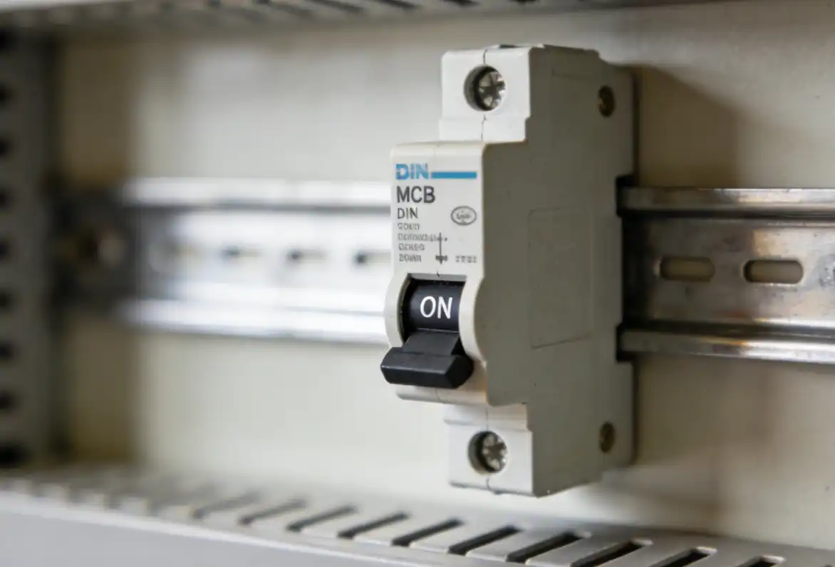
Only if the exact manufacturer documentation gives a suitable PV/DC rating for the actual voltage, current, breaking duty and pole connection. An AC ampere rating or similar housing is not proof of DC suitability.
No universal rule applies. The decision depends on parallel-string reverse current, module maximum-series-fuse information, conductor limits, inverter instructions, array topology and local electrical rules.
A PV circuit breaker opens automatically for defined overcurrent conditions. A DC isolator or switch-disconnector is selected mainly for switching and maintenance isolation. One device may have both functions only when its documentation proves both.
A manufacturer may require poles in series to reach a documented DC interruption voltage or fit a system arrangement. The number, order, barriers and polarity are part of the tested configuration. Follow the exact device diagram.
Calculate the maximum PV circuit voltage from the module and string data at the required minimum temperature. Then choose a PV/DC device whose rating covers that voltage under the approved pole arrangement.
Sometimes, but not automatically. Check the product standard, marking and manufacturer data for suitability for isolation, switching duty, lockability and the required installation conditions.
It is evidence that the product has a defined photovoltaic application under the stated certification system. You must still match voltage, current, poles, wiring, breaking capacity, terminals, environment and local requirements.
Use qualified personnel and the approved safety process. Review the trip event, device identity, pole wiring, conductor and terminal condition, heat or burn signs, enclosure ingress, inverter alarms and system changes before any reset or replacement.
Safety notice: This guide supports technical discussion and procurement. It is not a wiring design, code interpretation, protection study or authorization to work on energized PV equipment.
Use the local electrical code, authority having jurisdiction, utility rules, approved single-line, manufacturer instructions and qualified PV electrical personnel. Never improvise DC pole connections, bypass protection, open live equipment or treat the article’s conceptual examples as project settings.
After qualified personnel define the circuit, send SENTOP the single-line, maximum voltage and current, fault duty, pole diagram, conductor and enclosure data, destination standard, quantity and document needs. We can help organize model matching, sample review, OEM requirements and bulk supply.
