
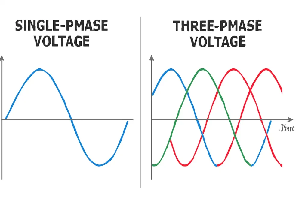
You can see a big difference between single phase voltage and three-phase voltage when you check how much power they give. Single phase voltage uses one alternating current. Three-phase voltage uses three currents together for more power. For example, a single-phase circuit at 120 volts and 20 amps gives 2,400 watts. A three-phase circuit with the same voltage and current gives about 4,157 watts. This almost double power shows why it is important to know about single phase voltage and three-phase voltage. Picking the right one helps you get the power you need at home, at work, or for big machines.
Key Takeaways
- Single phase voltage uses one alternating current. It works best for homes and small businesses. These places do not need a lot of power.
- Three phase voltage uses three alternating currents. It gives more power and smoother, steady energy. This is good for big machines and large buildings.
- Three phase systems have more complex wiring. They give higher efficiency and less energy loss. Motors work better with three phase systems.
- You should choose the right system for your needs. Think about power needs, cost, and equipment. Single phase is cheaper and easier to use. Three phase is better for heavy loads and saves money over time.
- You can connect single-phase devices to a three-phase system. Always ask a licensed electrician for safe installation and upgrades.
Key Differences
Single Phase Voltage and Three-Phase Voltage
There are some big differences between single phase voltage and three-phase voltage. These differences change how much power you get. They also change how you set up the wires and how the voltage moves.
- Voltage Values:
Single phase voltage is usually 120 volts or 240 volts. Three phase voltage can be 208 volts, 240 volts, or even 415 volts in some places. The higher voltage in three phase voltage helps send more power to large machines or buildings. - Wiring:
Single phase voltage uses two wires. One wire is live and one is neutral. This setup is easy and good for homes and small shops. Three phase voltage uses three live wires. Sometimes it also has a neutral wire, like in a Wye setup. The extra wires help three phase voltage carry more power and stay steady, even if the load changes. - Waveform:
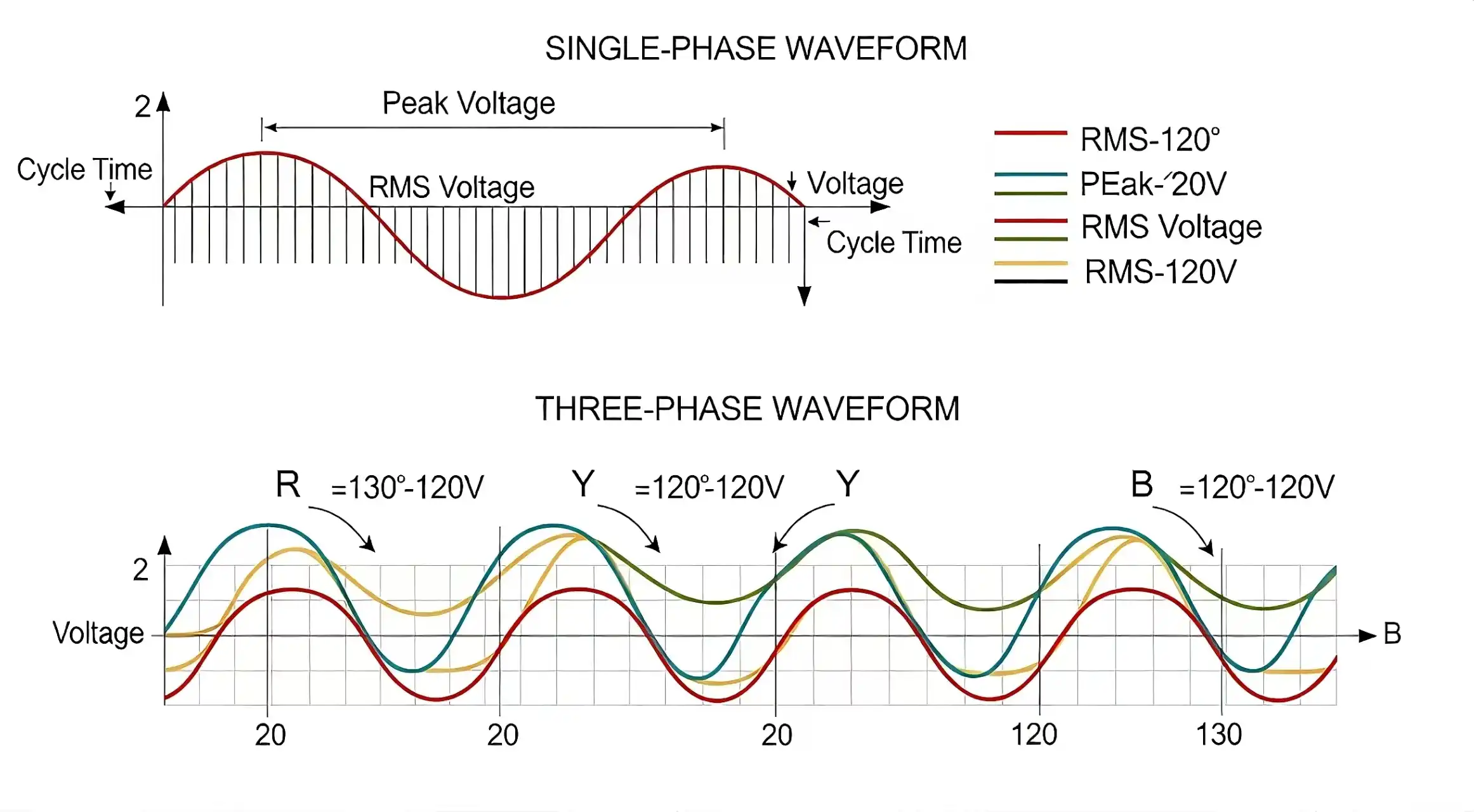
Single phase voltage has one wave that goes up and down. Three phase voltage has three waves. Each wave starts at a different time, 120 degrees apart. This keeps the power flow in three phase voltage smooth and steady. You get less flicker and more steady power for big equipment.
Tip:
To measure power in single phase voltage, you only need one wattmeter. For three phase voltage, you often need two wattmeters, especially in three-wire systems. This gives you a correct reading of the total power.
Main Distinctions
The main differences between single phase voltage and three-phase voltage are in how they give power, their wiring, and what they are used for. The table below shows these differences in a simple way:
| System Type | Typical Nominal Voltage(s) | Wiring Configuration | Waveform Details | Common Uses |
|---|---|---|---|---|
| Single Phase | 120 V or 240 V | Two wires (live and neutral) | One AC waveform | Homes, small businesses |
| Three Phase (Wye) | 208 V (line), 120 V (phase) | Three live wires + neutral | Three AC waveforms, 120° apart | Power distribution, mixed loads |
| Three Phase (Delta) | 240 V | Three live wires (no neutral) | Three AC waveforms, 120° apart | Factories, large motors |
Both single phase voltage and three-phase voltage can have small changes in voltage, usually between ±5% and ±10%. In three phase voltage, the Wye setup uses a neutral wire to keep voltage steady when the loads are not even. The Delta setup does not use a neutral wire, but it can still work if one part fails. This makes three phase voltage better for big machines.
When you pick between single phase voltage and three-phase voltage, think about how much power you need. Also think about how hard the wiring will be and what machines you want to use. Three phase voltage gives more power and smoother delivery, so factories and big buildings use it. Single phase voltage is best for homes and small shops where you do not need as much power.
What is Single Phase Voltage?
Definition
Most people use single phase voltage at home or in small offices. It is the main way to get electricity for lights and small machines. Single phase systems have two wires. One wire is called phase or live, and the other is neutral. In North America, the voltage is usually 120 volts or 240 volts. In many other places, it is 230 volts. The voltage moves in a smooth wave that goes up and down. This happens many times every second. In North America, it happens 60 times each second. In most other places, it happens 50 times each second.
| Region/Area | Typical Voltage Level(s) | Frequency (Hz) |
|---|---|---|
| United States, Canada | 120 V, 240 V | 60 |
| Europe, Africa, Asia | 230 V | 50 |
| United Kingdom | 230 V | 50 |
| Brazil | 127 V, 220 V | 60 |
| Japan | 100 V, 200 V | 50 or 60 |
How It Works
Single phase voltage sends one wave of alternating current. This wave goes from positive to negative values. It makes energy flow smoothly. When you plug in your devices, you use this system. The single AC waveform rises and falls in a steady way. This makes single-phase power simple for homes. The wiring is not hard to set up. This keeps costs low and makes it easy to install. You can count on single-phase power to give steady voltage for small things.
Common Uses
Almost every home and small business uses single-phase power. It runs your fridge, washing machine, air conditioner, and lights. It also works for computers, printers, and other office tools. Single phase voltage is best for places that do not need lots of power at once. In homes and small shops, single-phase systems are simple and work well. Studies show single-phase power helps balance loads and lower losses in local networks. Smart meters and new data tools help your single phase systems work well, even when many people use power at the same time.
💡 Tip: If you want to run big machines or heavy tools, you might need more than single phase voltage. For most daily needs, single-phase power gives you all the voltage you need.
What is Three Phase Voltage?
Definition
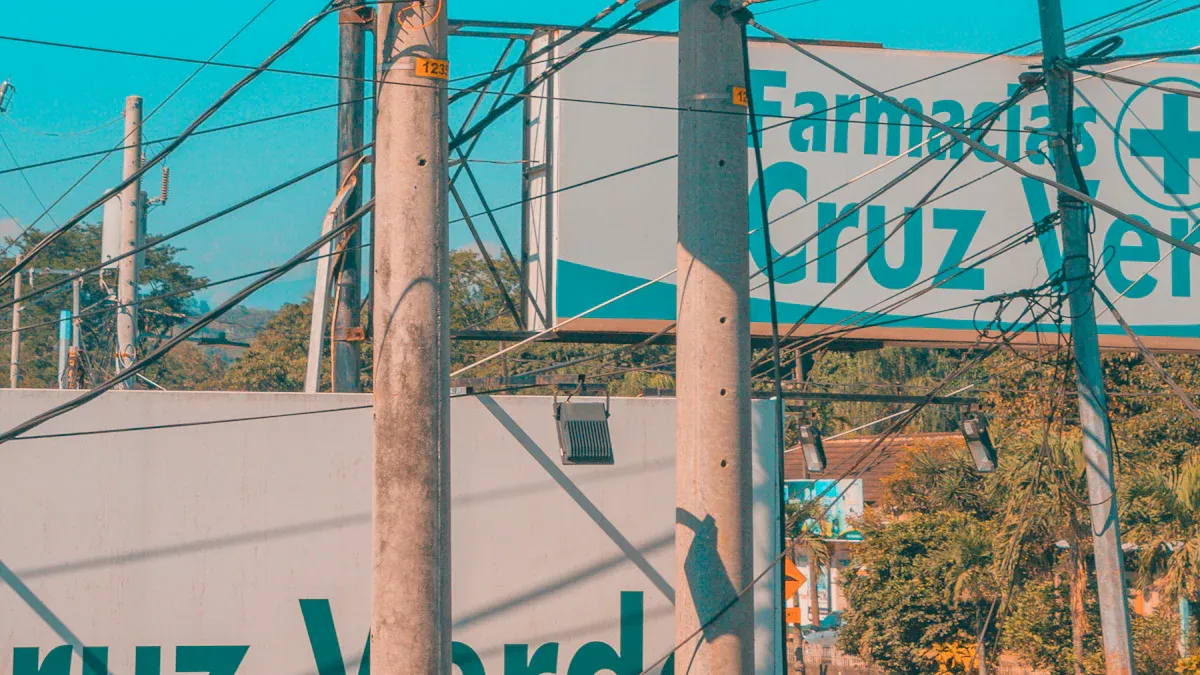
You can find three phase voltage in big factories and tall buildings. It is used where a lot of power is needed. This system has three wires. Each wire carries its own alternating current. Sometimes, there is a fourth wire called neutral. The voltage in three phase voltage is higher than in single phase voltage. In factories, Delta setups use 480V or 600V. Wye setups use 208/120V or 480/277V. These setups help send more power and make wiring easier.
| Parameter | Delta Configuration | Wye Configuration |
|---|---|---|
| Neutral Wire Presence | Absent | Present |
| Grounding Complexity | More complex | Simpler |
| Voltage Type | Phase-to-Phase only | Phase-to-Neutral available |
| Typical Voltage Levels | 480V, 600V | 208/120V, 480/277V |
| Efficiency at High Load | High | Moderate |
| Common Applications | Industrial motors, welding | Residential and commercial power distribution |
How It Works
Three phase voltage uses three AC waves. Each wave starts at a different time, 120 degrees apart. This means the voltage peaks at different times for each wire. There is always one wave at its highest point. This gives a steady flow of power. Three-phase power never drops to zero like single phase. This makes it very stable and reliable. Tests show three-phase power can give up to 73% more power than single phase voltage. It also loses less energy, about 25-30% less. You can use smaller wires for the same power. This saves money and space.
- The 120-degree difference keeps power steady and motors run smooth.
- Tools like multimeters and oscilloscopes check the voltage and show the waves.
- These tools prove three-phase power gives steady energy with fewer drops.
- The voltage between two phases is about 1.73 times higher than from phase to neutral. This lets you move more power with fewer wires.
🛠️ Tip: Think of three phase voltage like a three-cylinder engine. Each cylinder fires at a different time, so the engine runs smoothly. In the same way, three-phase power keeps your machines running without stops or surges.
Common Uses
You see three phase voltage in places that need lots of power. Factories use it for big motors, pumps, and heavy machines. Large offices and hospitals use it for elevators, air conditioning, and lights. Data centers use three-phase power to keep servers working well. Utility companies use three phase systems to send electricity far away. Three-phase systems can power both single-phase and three-phase devices. This makes them useful for many jobs. The world’s power grid uses lots of wires and big transformers to send three phase voltage to cities and industries. This helps keep power steady and efficient for everyone.
Single-Phase vs. Three-Phase
Pros and Cons
When you look at single-phase power and three-phase power, you can see they work differently for different jobs. Each one has things it does well and things it does not do as well. The table below shows the main points so you can compare them:
| Aspect | Single-Phase Power | Three-Phase Power |
|---|---|---|
| Voltage | Starts at 230V, frequency ~50 Hz | Voltage stays steady due to three phases offset by 120° |
| Power Capacity | Best for units up to 5 HP | Can run heavy industrial motors without extra starters |
| Power Delivery | Voltage rises and falls, not constant | Voltage never drops to zero, smooth power delivery |
| Motor Operation | Small motors may need starters | No extra starters needed for heavy motors |
| Installation Complexity | Simple wiring | Needs three wires plus neutral, more complex |
| Cost | Lower installation cost | Higher cost due to more wires and higher voltage |
Single-phase power is good for homes and small stores. It is cheaper to put in and uses easy wiring. Three-phase power is better for factories and big buildings with large machines. It costs more at first but gives steadier voltage and more power.
💡 Note: If you only want to use lights, TVs, or small tools, single-phase power is enough. If you need to run big motors or heavy machines, three-phase power is the better pick.
Power Delivery
How each system sends power changes how your devices work. In single-phase power, the voltage goes up and down like a wave. Sometimes, the power drops to zero. Motors or pumps may start slowly or shake more. You might need extra parts to help motors start.
Three-phase power sends three waves of voltage, each starting at a different time. The voltage never drops to zero. This keeps the power smooth and steady. Motors start fast and run without shaking. You can use three-phase power for big machines, elevators, and air conditioners. Data centers and hospitals use it to keep important things running all the time.
- Single-phase power is good for small jobs, but three-phase power is better for big jobs.
- Three-phase power has less voltage drop and fewer power cuts.
- You can use smaller wires with three-phase power, which saves space and money in big buildings.
Efficiency
Efficiency means how well a system uses the energy you give it. Single-phase power loses more energy because all the current goes through one wire. This can make more heat and waste energy. Motors on single-phase power often need more energy to start and run.
Three-phase power spreads the load over three wires. This makes less heat and wastes less energy. Motors run cooler and last longer. You save money on repairs and energy bills. Big factories and data centers use three-phase power for this reason.
Here is a quick look at how efficiency and cost compare:
| Aspect | Single-Phase Power System | Three-Phase Power System |
|---|---|---|
| Voltage Levels | Typically 120V or 230V | Typically 208V to 480V |
| Efficiency | Lower efficiency, higher losses | Higher efficiency, less energy lost |
| Load Balancing | No load balancing | Balanced load, less risk of overload |
| Motor Performance | Less smooth operation | Smooth startup, less vibration |
| Cost | Lower installation and equipment cost | Higher initial cost, better for high power needs |
- Factories use three-phase power for machines that work well.
- Big air systems and elevators need three-phase power to work smoothly.
- Data centers pick three-phase power to handle lots of work and avoid stops.
🛠️ Tip: Even though three-phase power costs more to set up, you save money later because it works better and needs fewer repairs.
When you choose between single-phase and three-phase, think about what you need. If you want simple and cheap power for your home, single-phase power is best. If you need steady voltage and lots of power for big machines, three-phase power is the best choice.
Applications of Three-Phase Power
Industrial Use
Factories almost always use three-phase power. This system gives enough power for big machines and motors. Heavy pumps and equipment start easily and run without stopping. Three-phase power helps machines stay cool and not overheat. It also cuts down on energy loss. You can use it for large conveyor belts and welding machines. Big compressors also work well with steady power. Because the power is steady, machines break less often. This means less time fixing things and more time working. You can use smaller wires, which makes setting up cheaper.
Commercial Use
Three-phase power is used in big buildings and busy places. You find it in hospitals, malls, and office towers. Data centers also use it for their computers. These places need lots of power for lights and elevators. Air conditioning and computers also need steady power. Three-phase power keeps everything running at once. It helps stop energy loss and keeps voltage from changing too much. This makes equipment last longer and stay cool. Balanced power means you do not get overloads or blackouts. Many buildings use three-phase power for important systems. HVAC, lighting, and data centers all need steady power. You can count on three-phase power to work every day.
- Three-phase power gives lots of power for big places.
- It keeps voltage steady and saves energy.
- All your equipment gets balanced power.
Residential Use
Most homes use single-phase power. But some big houses or apartments need more. If you have a large air conditioner or pool pump, you might need three-phase power. Elevators in buildings also use this system. Three-phase power gives more power for big appliances. It also makes them run smoother. You can still use single-phase devices with three-phase power. Just connect them to one phase. This way, you get extra power for bigger machines. Three-phase power works for both small and large needs.
💡 Tip: Three-phase power is not only for factories. You can use it at home or in offices if you need more power or want to run heavy machines.
Choosing the Right System
Assessing Needs
You should start by looking at what kind of power you need. Make a list of all the devices and machines you want to use. Think about how much power each one needs. If you plan to use only lights, TVs, and small tools, a single-phase power supply will work well. For bigger machines or many devices running at once, you may need more power from a three-phase system.
Field surveys help you make smart choices. Here is a simple way to check your needs:
- Gather details about your wiring, voltage, and the type of equipment you use.
- Use special tools to measure voltage, current, and other power details.
- Look at the data with software to spot trends and check if your system meets standards.
- Find out when and where power problems happen.
- Use this information to decide if you need to upgrade your system.
Statistical models can also help. They use past power use and weather to guess how much power you will need. This helps you avoid overloads and keeps your system running well.
Cost Factors
You need to think about both the first cost and the long-term cost. A single-phase power supply costs less to install. The wiring is simple, and you do not need many parts. Three-phase systems cost more at first because they need extra wires and special equipment. Over time, three-phase systems can save money if you use a lot of power. They waste less energy and help machines last longer.
| System Type | Initial Cost | Long-Term Savings | Best For |
|---|---|---|---|
| Single-Phase | Low | Moderate | Homes, small shops |
| Three-Phase | High | High | Factories, big offices |
💡 Tip: If you plan to add more machines later, think about the cost to upgrade now. It may save you money in the future.
Reliability
You want your power to be steady and safe. Single-phase power supplies work well for small loads. They are easy to fix and keep running. Three-phase systems give more reliable power for big jobs. They keep voltage steady and help machines run without stops. If you have important equipment, three-phase power can prevent downtime.
If you think about upgrading, check your current wiring and power needs. Sometimes, you can switch from single-phase to three-phase by adding wires and changing your main panel. Always ask a licensed electrician before making changes.
⚡ Note: Choosing the right system helps you avoid power problems and keeps your equipment safe.
Glossary
Key Terms
Here are some key words you saw in this blog. These terms help you understand single phase voltage and three-phase voltage better.
- Alternating Current (AC)
You see this type of electricity in most homes and buildings. The current changes direction many times each second. This helps send power over long distances. - Voltage
Voltage tells you how strong the electric force is. You can think of it like water pressure in a hose. Higher voltage means more power can move through the wires. - Phase
A phase is one part of an electric cycle. In single phase, you get one wave. In three-phase, you get three waves that start at different times. - Neutral Wire
This wire carries current back to the source. It helps keep the voltage steady and safe. You find it in both single phase and three-phase systems. - Live Wire (Hot Wire)
This wire brings electricity to your devices. You must be careful with it because it can shock you. - Wye (Star) Connection
You see this setup in three-phase systems. It uses three live wires and a neutral wire. This helps balance the load and keeps voltage steady. - Delta Connection
This is another way to set up three-phase power. It uses three live wires but no neutral wire. Factories use this for big machines. - Load
A load is anything that uses electricity, like a light, motor, or computer. - Waveform
This shows how voltage or current changes over time. In single phase, you see one wave. In three-phase, you see three waves.
💡 Tip:
If you ever feel unsure about these terms, you can look back at this glossary. Knowing these words helps you talk with electricians and make smart choices about your power needs.
- Frequency (Hz)
Frequency tells you how many times the current changes direction each second. In the U.S., you see 60 Hz. In many other places, you see 50 Hz. - Power Capacity
This tells you how much work your system can do. Three-phase systems give you more power for big jobs. - Efficiency
Efficiency shows how well your system uses energy. Higher efficiency means less waste and lower bills.
You have learned the big differences between single phase voltage and three-phase voltage. The table below shows how they are not the same in voltage, wiring, and how they give power:
| Feature | Single-Phase Voltage | Three-Phase Voltage |
|---|---|---|
| Voltage | Up to 230V | Up to 415V |
| Wire Setup | 2 wires | 3 or 4 wires |
| Power Delivery | Fluctuates | Steady and continuous |
| Efficiency | Lower | Higher |
Knowing this helps you pick the best system for what you need. If you want to make big changes, ask an expert for help. You can read more in books about electricity or look at good websites.
FAQ
What is the main reason to choose three-phase power over single-phase?
You get more power and smoother delivery with three-phase. This helps big machines run better. Three-phase also saves energy and keeps voltage steady. Factories and large buildings often use it for these reasons.
Can you use single-phase devices on a three-phase system?
Yes, you can connect single-phase devices to a three-phase system. You use one phase and the neutral wire. This lets you run regular home appliances in places with three-phase power.
Is three-phase power safer than single-phase power?
Both systems can be safe if you follow the right steps. Three-phase power uses higher voltage, so you must be extra careful. Always ask a licensed electrician for help with wiring or repairs.
Why do homes usually have single-phase power?
Most homes use single-phase power because it meets daily needs. Lights, TVs, and small appliances do not need much power. Single-phase wiring costs less and is easy to install.
How do you know if your building uses single-phase or three-phase power?
You can check your main electrical panel. If you see two wires (live and neutral), you have single-phase. If you see three or four wires, you likely have three-phase.
You can also ask your utility company.
The following information may be of interest to you
Single vs Three Phase MCCB: Key Differences
What You Need to Know About Three-Phase Solar Inverters
What Makes D-type MCBs Different from Other Circuit Breakers
Single Phase vs Three Phase Electricity: Which is Best for You?

Discover more from SENTOP Electrical Co., Ltd
Subscribe to get the latest posts sent to your email.
