
One supply, several circuits
The internal distribution path feeds multiple outgoing ways, each protected by the fuse arrangement specified for that circuit.
A fused distribution box divides one incoming supply into multiple outgoing circuits and uses fuse links for specified overcurrent protection. The name is descriptive—not a universal certification category—so the complete assembly, fuse system, voltage, fault duty, switching functions, and documentation must be verified together.
Background: example DIN-rail fuse box with a contactor and time switch for outdoor lighting in a German shop. Photo: Pittigrilli / Wikimedia Commons, CC0 1.0. The source was already cropped; it is further center-cropped and darkened in CSS for text legibility. This regional example does not establish product ratings, SCCR, selectivity, compatibility, certification, or a safe working state.
Use the product name to begin the conversation. Use the nameplate, certificates, single-line, data sheets, and complete assembly verification to approve it.
The internal distribution path feeds multiple outgoing ways, each protected by the fuse arrangement specified for that circuit.
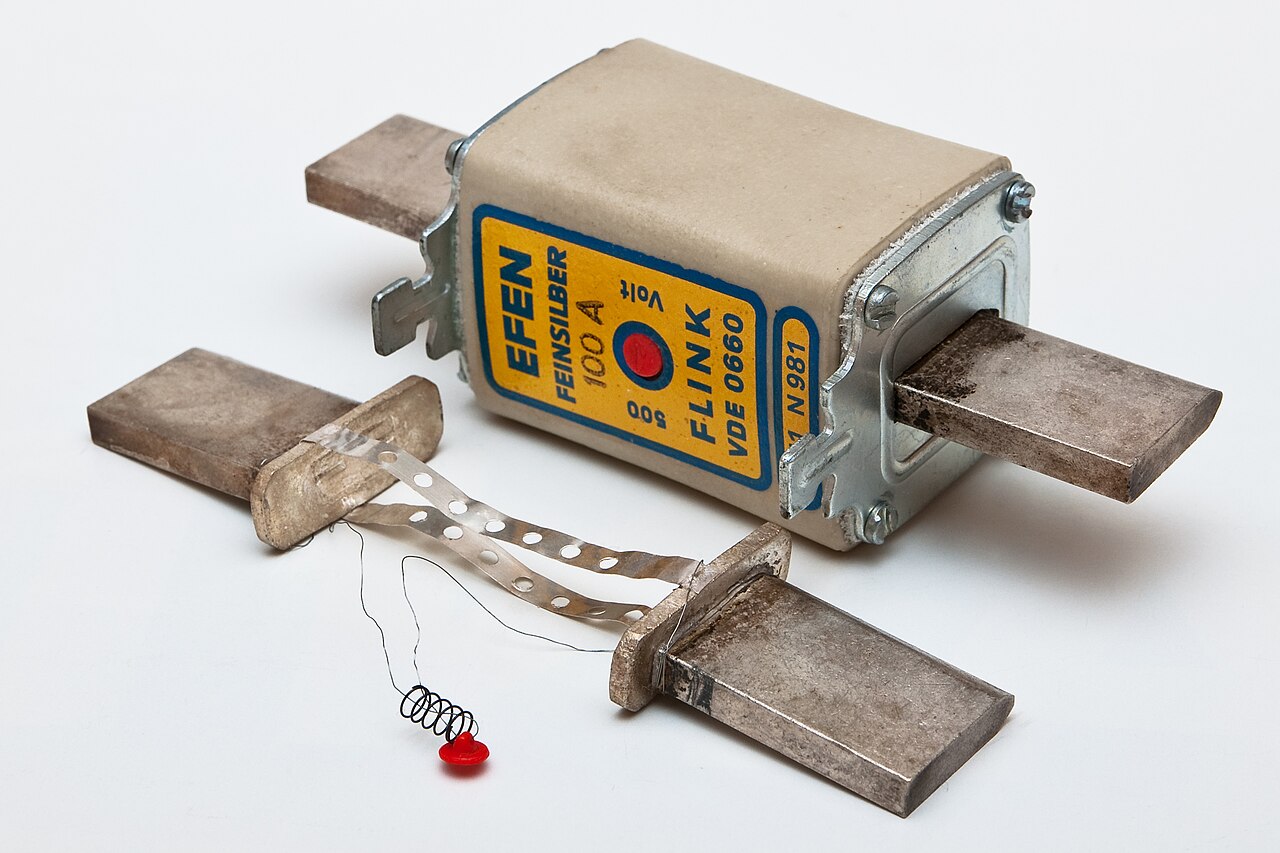
When the fuse reaches its documented time-current operating condition, its current-responsive element opens. It is non-resettable.
“Fuse box,” “fused board,” and “fused panel” do not prove a standard, main disconnect, service role, or fault rating.
Confirm fuse link, holder or switch, bus, terminals, enclosure, conductors, source, protection study, and destination-market evidence.
A fused distribution box or fused distribution board is a descriptive term for a multiway assembly. It does not create one worldwide product category. A North American fused panelboard, an IEC power switchgear and controlgear assembly, and an IEC distribution board for operation by ordinary persons can have different scopes, ratings, verification routes, and user-access rules.
“Fuse box” or “fuseboard” is informal search language. It may refer to a legacy residential enclosure, a modern consumer unit, a compact control assembly, or an industrial feeder panel. For procurement, replace the informal name with the actual product category and destination standard.
For a broader component map, see the upgraded guide to single-phase distribution box parts. Compare system architectures in single-phase vs three-phase DB boxes.

This shows the system-level relationship only. The approved single-line diagram, assembly documentation, protection study, conductor schedule, neutral/PE design, and local rules control the real installation.
The actual source defines AC/DC duty, voltage, frequency, earthing, conductor arrangement, and maximum and minimum prospective fault current.
Approved lugs receive the supply. A documented switch, disconnector, fusible switch, or upstream device provides required operating functions.
The internal path supplies multiple outgoing ways within the assembly’s current, temperature-rise, connection, and short-circuit limits.
Each selected fuse carries normal current and responds according to its documented time-current characteristic under abnormal overcurrent.
Terminals connect the protected circuit to its conductor and load. Labels, schedules, and approved spare references support safe lifecycle control.
Neutral switching, fusing, isolation, bonding, and terminal arrangement depend on the supply and earthing system, project design, product approval, and local rules.
PE or equipment-grounding conductors follow their dedicated protective path. Never switch or interrupt a PE or PEN conductor as an ordinary pole; follow the actual earthing system and locally adopted rules.
A photo can show where components sit. It cannot prove current, temperature rise, fault duty, conductor acceptance, switching capability, or assembly compliance.
Provides mounting, access restriction, cable entry, working space, and a stated environmental boundary.
Verify IP code or NEMA/UL Type on its native market basis—do not assume a direct equivalence.Accept the assigned supply conductors or bus connection.
Verify Cu/Al marking, conductor size and class, quantity per opening, temperature condition, torque, and bend space.Provides only the switching, disconnecting, isolation, or protective functions declared for the exact product.
Verify poles, neutral sequence, utilization duty, lockability, source scope, and service role.Makes the incoming path available to multiple outgoing ways.
Verify rated current, simultaneous loading, temperature rise, phase/neutral layout, short-circuit basis, and assembly verification.Holds the fuse link and may add a separately documented operating function.
Verify exact physical system, voltage, current, AC/DC duty, short-circuit data, rejection features, and permitted operation.Provides the overcurrent function assigned by its product data and coordination study.
Verify category or class, current, voltage, rated breaking or interrupting capacity, time-current curve, and replacement identity.Connect each protected way to its named load or downstream distribution point.
Verify conductor material/range, preparation, strip length, torque or actuation, routing, labels, and spare ways.Provide the supply-system-specific current return and protective-conductor interfaces where required.
Verify actual earthing system, neutral rating, bonding location, all-source isolation, and PE/PEN restrictions.Add separate functions only when the assembly and project approve them.
Verify function, ratings, coordination, internal connection, device family, documentation, and destination-market acceptance.
During normal service, current passes through the fuse element within the conditions declared for the selected product and installation. When abnormal current reaches the fuse’s operating region, energy in the element causes it to open. The operating time depends on current magnitude and duration, fuse construction, ambient and mounting conditions, circuit impedance, voltage, load inrush, and the exact category or class.
A temporary motor, transformer, capacitor, converter, or electronic-load inrush may be acceptable only when its profile is coordinated with the fuse curve. A sustained overload can operate the fuse after a delay. A high prospective short circuit can be interrupted only within the exact fuse voltage and breaking-capacity conditions and the complete assembly’s documented fault-rating basis.
Some fuse systems are current-limiting within stated regions and conditions. Do not turn that into a universal claim. The selected link, holder or switch, upstream/downstream devices, available fault current, system voltage, and complete assembly determine the real result.
For a dedicated comparison, use the guide to circuit breakers vs fuses. If the protected interface is a terminal block rather than a distribution assembly, see feed-through vs fuse terminal blocks.
Do not translate an IEC utilization category into a North American fuse class. Each system has its own dimensions, rejection features, time-current behavior, standards, and combination requirements. The full part number and the approved holder or switch matter as much as the headline current.
| Designation | What it means in context | What buyers must not assume |
|---|---|---|
| IEC gG | A full-range general-application fuse category within the applicable IEC fuse system. | It is not a universal holder format, voltage, current, or substitute for a named UL class. |
| IEC aM | A partial-range motor-circuit fuse category used with separately coordinated overload protection. | The fuse alone does not provide every required motor overload function. |
| IEC gPV | A fuse category for PV source circuits under its applicable product data and IEC 60269-6 route. | It is not a generic DC or battery fuse and not a semiconductor high-speed fuse. |
| Semiconductor fuse | An application-specific high-speed protection route under IEC 60269-4 or the applicable certified product data. | “Fast” does not make it suitable for every converter or semiconductor device; energy coordination remains product-specific. |
| UL fuse class | Class CC, J, R, T, L, and other UL 248 classes have defined physical and performance requirements. | Equal amperes or physical fit do not make different classes, speeds, or rejection systems interchangeable. |
Wording discipline: “Time-delay,” “fast-acting,” and “high-speed” describe characteristics in a product context. They are not universal replacements for the correct standard, category, class, link, holder, voltage, curve, and coordination evidence.
For PV and battery projects, use the dedicated DC overcurrent protection guide and verify the required DC isolator function separately.
State the country and exact equipment category before asking whether a product is “IEC” or “UL.” A component certificate is not a completed-board approval.
IEC 61439-1 is used with the relevant Part 2 onward. Industrial power switchgear and controlgear assemblies commonly use IEC 61439-2. Only equipment within IEC 61439-3’s narrower scope should be called a distribution board intended for operation by ordinary persons.
IEC 60269 parts distinguish general, authorized-person/industrial, household/similar, semiconductor, and PV fuse routes. IEC 60947-3 covers switches, disconnectors, switch-disconnectors, and fuse-combination units.
The complete panelboard has its own markings, current and voltage ratings, SCCR, approved devices, enclosure, service-equipment conditions, and installation limitations. UL 248 covers fuse families; UL 4248 covers fuseholders.
UL 98 covers applicable enclosed or dead-front switches, including suitable fusible switches. UL 508A covers factory-wired industrial control panels. Neither term automatically describes a UL 67 multiway panelboard.
A complete system may combine them. Each function still needs its own rating, coordination, and approved assembly interface.
Operates according to the exact link’s current, time, voltage, and fault conditions.
Does not automatically provide switching, isolation, residual-current, or surge protection.A breaker may add switching, indication, accessories, or adjustable protection depending on the exact model.
Compare the MCB or MCCB at actual voltage and fault duty.An RCCB is an RCD without integral overcurrent protection. Its RCD type and sensitivity must suit the load and rules.
Provide coordinated overcurrent protection; see RCCB options.A marked RCBO combines both functions, but its curve, current, poles, breaking capacity, RCD type, and board fit still require approval.
It is not an SPD or a universal replacement for every protection function.An SPD diverts surge current and limits specified transient overvoltages within its coordinated installation.
It is not circuit overcurrent or personnel-shock protection; select the SPD system separately.Switching, load breaking, disconnection, isolation, all-pole operation, and neutral sequence are separate declared properties.
A fuseholder or removed link cannot be assumed to provide these functions.
Industrial machinery and motor-control feeders may use fuse systems coordinated with motor starters and separate overload protection. Commercial or tenant sub-distribution may use a listed or verified fused assembly where access, metering, neutral arrangement, labels, and the local installation rules support it.
Process plants and critical feeder groups may value selective protection, but selectivity must be documented for the exact upstream/downstream devices, voltage, available fault-current range, and source modes. There is no universal current ratio that proves it.
PV, battery, telecom, controls, and data infrastructure can use fused AC or DC distribution only when the fuse family, voltage, polarity, source fault behavior, holder or switch, enclosure, and complete system route match. Temporary or site power adds environmental, mechanical, inspection, earthing, and qualified-oversight requirements.
Three-phase projects can use the upgraded three-phase distribution box guide. To determine physical way count and expansion constraints, use the separate guide to choosing the right distribution board size.
Convert “I need a 100 A fuse box” into a verifiable system specification. This workflow supports engineering and procurement; it is not an installation procedure.
State country, adopted rules, required listing/certification, and exact category: IEC PSC assembly, IEC DBO, UL panelboard, UL industrial control panel, or another accepted route.
Output: named standard basis—not “IEC/UL compliant.”Record AC/DC, voltage, frequency, phases/poles, earthing, neutral, normal/alternate source modes, loads, duty, inrush, conductors, and growth.
Output: approved one-line and branch schedule.Maximum fault current tests interruption and withstand. Minimum fault current tests whether protection operates adequately in weak-source or remote-end conditions.
Output: fault-study values by source mode and location.Specify standard, category/class, current, voltage, breaking/interrupting rating, time-current behavior, format, rejection features, and approved holder or switch.
Output: full part references and curves.Check incoming lugs, busbars, fuse bases, switches, terminals, conductors, temperature conditions, simultaneous loading, ventilation, and connections.
Output: documented lowest applicable limit or exact combination rating.Keep fuse interrupting data separate from holder/switch and assembly ratings. Verify series/conditional ratings and selectivity only for the exact combination and voltage.
Output: SCCR/IEC fault basis plus coordination evidence.Specify switching duty, all-source isolation, neutral treatment, lockability, access, labels, LOTO points, stored energy, backfeed controls, and responsible qualified roles.
Output: operating and safe-work boundary.Request certificates, drawings, test/verification records, manuals, approved spares, circuit labels, inspection plan, change notices, and training or handover records.
Output: auditable approval package.Never use a fuse or a non-load-break fuseholder to open a loaded circuit. Before work inside an enclosure, qualified personnel must identify every source, de-energize where required, isolate and lock/tag the energy sources under the site procedure, address stored energy, and verify absence of voltage—including induced voltage and backfeed—with suitable, correctly rated test equipment.
Treat the equipment as energized until the required verification is complete. A selector in OFF, an open fuse, a tripped upstream device, a dark indicator, or a remote stop command is not by itself proof of an electrically safe work condition.
After a fuse operates, investigate the cause and the condition of the fuseholder, switch, conductors, connections, protected equipment, and assembly as the product and site procedures require. Install only the documented replacement. Never bridge, bypass, up-rate, or repeatedly replace a fuse to keep equipment running.
For procurement-side maintenance planning, the control-cabinet component framework helps define labels, terminals, and service interfaces before production.

Send enough information to approve the fuse system and the complete assembly together. Unknown fields should be marked “confirm before approval,” not inferred from a marketing label.
Destination country, adopted rules, required certification/listing, exact equipment category, quantity, OEM branding, packing, and delivery location.
Application role, all sources and modes, AC/DC, voltage, frequency, phases/poles, earthing system, neutral, and all-source isolation needs.
Incoming design current, every outgoing circuit, duty, demand/diversity, inrush, conductors, protected equipment, spare ways, and growth plan.
Maximum and minimum prospective fault current by source mode, study point, voltage, protection objective, and required clearing/withstand basis.
Exact class/category, current, voltage, AC/DC duty, breaking/interrupting rating, curve requirement, physical system, rejection feature, and spare reference.
Compatible holder, carrier, base, or fuse-combination device; switching/isolation duty; lockability; indication; terminal data; and replacement procedure.
Bus and terminal ratings, simultaneous loading, temperature-rise basis, SCCR or IEC short-circuit data, conditional combinations, enclosure, cable entry, and mounting.
Coordination tables/study, certificates, drawings, schedules, curves, routine/design verification, test records, labels, manuals, training, spares, and change control.
Environment field: State ambient, altitude, ventilation, corrosion, condensation, pollution, mechanical conditions, material, and either the required IEC IP code or North American NEMA/UL enclosure Type. Do not treat those systems as a casual one-to-one conversion.
These pages own the adjacent decisions; this article stays focused on the fused distribution assembly.
Review enclosure and distribution product options before requesting a project-specific match.
Explore distribution boxes →Separate overload, short circuit, residual-current, surge, and isolation functions.
Use the selection guide →See how phase balance, poles, voltage, and applications change the specification.
Read the three-phase guide →Request exact-model and exact-assembly evidence for the destination market.
View standards support →These answers support specification and purchasing. They do not replace the project protection study, locally adopted rules, manufacturer instructions, or qualified-person safe-work procedures.
A fused distribution box is a complete low-voltage distribution assembly in which one incoming supply is divided into multiple outgoing circuits and fuse links provide the specified overcurrent protection. The name alone does not establish a main disconnect, isolation function, service-equipment suitability, fuse system, or assembly short-circuit rating.
Not necessarily. “Fuse box” and “fuseboard” are informal terms that can describe legacy residential equipment, a consumer unit, a compact industrial assembly, or another enclosure. Approve the exact product category, standards, components, ratings, drawings, and application rather than relying on the informal name.
No. A fuseholder mounts and connects a fuse link; it is not automatically permitted to break load current or provide verified isolation. Use a documented switch, disconnector, fuse-switch-disconnector, or fusible switch when the project requires that function, and follow its utilization category, markings, and instructions.
Equal amperes are not enough. The replacement must be the exact approved type or documented equivalent, including standard, class or category, voltage, AC/DC duty, breaking or interrupting rating, time-current characteristic, physical and rejection system, and holder or switch compatibility. Qualified personnel must investigate the cause and determine that re-energization is safe.
The fuse interrupting rating or IEC rated breaking capacity describes the fuse link under its specified conditions. The fuseholder, fusible switch, busbars, terminals, internal wiring, and complete panel have their own applicable SCCR, conditional short-circuit rating, or IEC assembly short-circuit data. A high-rated fuse does not automatically give every connected part the same rating.
Not by itself. A fuse provides the overcurrent function assigned by its product standard and coordination study. Residual-current protection, personnel-shock protection, surge protection, load switching, verified isolation, and all-pole disconnection are separate functions that require suitable devices and a coordinated system design.
They belong to different product routes and applications. IEC gG is a full-range general-application category; aM is a partial-range motor-circuit category used with separate overload protection; gPV is for PV source circuits; and UL fuse classes have their own dimensions, rejection features, and performance requirements. Do not translate one label into another or choose by physical fit alone.
Send the destination market and equipment category; one-line diagram; AC/DC voltage, frequency, phases, poles, earthing and neutral arrangement; load schedule and inrush; maximum and minimum fault current; exact fuse requirements; holder or switch function; assembly current and fault-rating basis; bus, terminals and conductors; environment and enclosure requirement; coordination evidence; drawings, certifications, test records, labels, spares, quantity, and destination.
Standards are summarized, not reproduced. Confirm the adopted edition, local amendments, exact product certificate, and manufacturer conditions for the project.
Send the one-line, branch schedule, source and earthing data, maximum and minimum fault current, fuse family, enclosure environment, destination standards, and required documents. SENTOP can support component and assembly matching; final design and approval remain with the responsible project professionals and authorities.
No universal fuse multiplier, breaking capacity, coordination ratio, enclosure rating, or maintenance interval is implied.
