Choosing the right distribution board size is important for your electrical system’s safety and efficiency. The correct distribution board size allows circuits to handle power without overheating or overloading. It also accommodates safety devices like circuit breakers and surge protectors, which protect your system from electrical dangers. A properly sized distribution board avoids crowding and leaves space for future needs, saving you money on upgrades later. By assessing your power needs, you ensure a strong and effective setup for both now and the future.
Tip: Safety comes first when selecting a distribution board size. A board that’s too small can harm your electrical system.
Key Takeaways
-
Add up the wattage of all your devices. This helps make sure your board can handle the power safely.
-
Count how many circuits you need for your appliances. Each circuit should cover certain areas or devices without overloading.
-
Pick a board with extra space for future needs. This makes it easier to upgrade as new technology comes out.
-
Follow safety rules like NEC and IEC to keep your panel safe. Regular checks help stop overloads and short circuits.
-
Ask a licensed electrician for help with panel size and setup. Their knowledge keeps things safe and wired correctly.
Key Factors to Find Your Panel Size

Calculating load requirements
Knowing your electrical load is the first step to pick your panel size. Add up the total power needed for your home or building. This means checking the wattage of all devices and appliances. For example, refrigerators, air conditioners, and lights add to the total load.
Rules like the National Electric Code (NEC) help with these calculations. Article 220 of the NEC explains how to figure out total demand load. Important things to check include connected watts, demand factors, and power factor. Demand factors adjust expected power use to handle peak loads safely.
You can use an Electrical Load Calculation table to make this easier. The table shows total power needs and helps find the amps your panel must support. Correctly calculating load stops circuits from overloading and ensures your distribution board fits your needs.
Tip: High-power devices like ovens and HVAC systems need more current. Always include them when sizing your panel.
Determining the number of circuits needed
The number of circuits depends on the appliances and devices you use. Each circuit powers specific areas or equipment, like kitchen outlets or lights. To choose your panel size, figure out how many circuits you need.
List all appliances and where they are located. For example, homes with many rooms may need separate circuits for lights, outlets, and big appliances like washers. Each circuit must handle the current without tripping breakers.
If unsure, check the amperage of your devices. High-amperage items, like electric water heaters, often need their own circuits. Knowing the number of circuits ensures your panel fits your needs without being overcrowded.
Note: Overcrowded panels can overheat and cause safety problems. Leave space for extra circuits when planning your distribution board.
Planning for future electrical expansions
Think about future needs when picking your panel size. As technology changes, you might add new devices or upgrade old ones. For example, solar panels or electric car chargers increase power demand.
Choose a distribution board with extra capacity to prepare for growth. Bigger panels let you add circuits without replacing the whole system. This saves money and keeps your setup working as your needs grow.
Check the amperage of future devices. High-capacity panels handle more current, making them good for long-term use. Planning ahead avoids expensive upgrades and ensures your panel supports future needs.
Tip: Ask a licensed electrician to check your future needs. They can suggest a panel that balances current use and room for growth.
Types of Electrical Panels and Their Applications
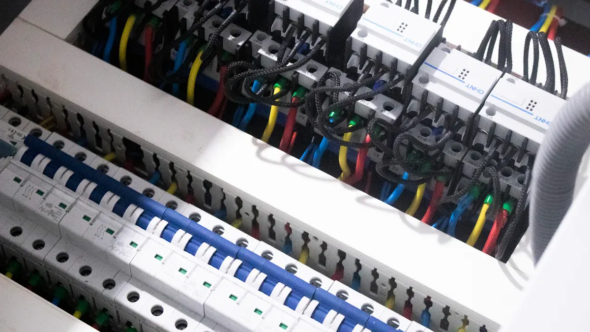
Residential distribution boards
A residential distribution board is the main control for home electricity. It sends power to circuits, ensuring each area gets enough electricity. These boards usually handle 120/240V single-phase power and support up to 400 amps.
You’ll see these boards in houses, apartments, and small buildings. They are light and made for indoor use, perfect as an indoor distribution board. Plug-on breakers are common, making setup and repairs simple. If upgrading your home’s electrical system, picking the right main panel keeps it safe and efficient.
Tip: Pick a board with space for future circuits.
Industrial distribution boards
An industrial distribution board is designed for factories, warehouses, and big buildings. It handles higher voltages and often uses three-phase power for heavy machines.
These boards can support up to 5,000 amps, much more than home boards. They use plug-on and bolt-on breakers, offering flexibility. Built with strong, UL-rated materials, they last in tough conditions. Modular designs make them easy to expand, great for growing businesses.
If your building needs a switch cabinet for complex systems, an industrial distribution board is reliable and powerful.
Note: Only professionals should install industrial panels to ensure safety.
Key differences in capacity and design
Knowing the differences between residential and industrial panels helps you choose wisely. The table below shows key features:
|
Feature |
Residential Load Centers |
Industrial Panelboards |
|---|---|---|
|
Voltage & Phase Configurations |
120/240V single-phase power |
Higher voltages and three-phase power |
|
Electrical Load Capacities |
Up to 400 amps |
Up to 5,000 amps |
|
Plug-on breakers only |
Plug-on and bolt-on breakers |
|
|
Durability & Components |
Lightweight design |
Heavier, UL-rated materials |
|
Expandability |
Fixed capacity |
Modular and expandable designs |
|
Cost |
More cost-effective |
Higher initial investment |
When choosing a main panel, think about voltage, load, and expandability. Residential boards are cheaper and good for homes. Industrial panels are stronger and handle more power for bigger needs.
Tip: Ask an electrician to help pick the right panel for you.
Ensuring Safety and Compliance in Panel Size Selection
Overload and short circuit protection
Keeping your electrical system safe means avoiding overloads and short circuits. Overloads happen when circuits use more power than they should. Short circuits occur when electricity flows the wrong way, causing sparks or fires. Both can be dangerous if not fixed.
To stay safe and prevent these problems:
-
Check your distribution board often to ensure wires are in good shape.
-
Plan circuits wisely to spread out power use evenly.
-
Use strong insulation to lower the chance of electrical issues.
-
Learn and share basic electrical safety tips with others.
These steps help reduce risks and keep your panel working well. For example, a 200-amp panel is popular for homes. It handles big appliances and leaves room for future needs.
Tip: Use circuit breakers that match your panel size and power needs.
Adhering to NEC, IEC, and regional codes
Following electrical codes is key to staying safe and avoiding problems. These rules guide panel size, setup, and care. The National Electrical Code (NEC) and International Electrotechnical Commission (IEC) are trusted standards.
Important rules include:
-
OSHA Rules: Keep the panel area clear and easy to access.
-
NEC Guidelines: Leave at least 3 feet (0.9 meters) of space in front of the panel and 30 inches (76 centimeters) of width.
-
Safety Checks: Follow these rules to make sure your panel is safe to use.
Sticking to these codes makes upgrades easier later. For instance, if you upgrade your panel, following NEC and IEC rules avoids delays and issues.
Note: Always hire a licensed electrician to confirm your panel meets all codes.
Importance of proper wiring and MCB sizing
Good wiring and the right miniature circuit breaker (MCB) size are vital for safety. Wrong wiring or an MCB that’s too small can cause overheating or fires.
Picking the correct MCB size stops overloads and protects your system. It also prevents unnecessary power cuts during faults. This makes it easier to find and fix problems quickly.
For example, if you have a 200-amp panel, use MCBs that fit the circuits. This ensures your system runs safely and efficiently.
Tip: Use quality wires and ask an expert to choose the right MCB size.
Practical Tips to Choose the Right Distribution Board
Customization options for specific needs
Start by knowing your unique needs for the distribution board. Customizing lets you adjust the size and features to fit. For example, during home upgrades, you may need extra circuits for new devices.
Check the equipment carefully when customizing. Look at the shell type—plastic or metal—and decide if it should be hidden or visible. Make sure the wiring is correct. The phase line, zero line, and ground must be set properly. These changes improve safety and how well it works.
Tip: Use an electric pen to test insulation and check all parts. This ensures your panel is set up safely and works well.
Balancing cost-effectiveness with quality
Choose a panel that balances cost and quality. A better-quality panel costs more but lasts longer and is safer. Check the space where the panel will go. Make sure the air switch frame has enough room and isn’t blocked.
Follow this checklist:
-
Pick the distribution board size based on your space and circuit needs.
-
Check the board’s design to ensure it’s strong and durable.
-
Test insulation to avoid electrical problems.
A good panel lowers repair costs and lasts longer. Cheaper panels exist, but focus on quality for better results.
Note: A strong panel saves money and keeps your electrical system safe.
Consulting a professional to find your panel size
If you’re unsure about the size, ask a licensed electrician. They can check your current and future power needs to match the right distribution board size. They also ensure it follows safety rules like NEC and IEC.
Electricians can suggest panels with extra space for future needs, like solar panels or car chargers. Their advice ensures your panel works well and stays safe.
Tip: Always hire certified electricians for installations. This avoids mistakes and ensures proper wiring.
Picking the right size for your distribution board keeps your electrical system safe and working well. The correct panel size stops overloads, allows for future upgrades, and meets safety rules. Good distribution boards lower risks and boost performance. For example:
|
Fact |
Meaning |
|---|---|
|
Shows why strong distribution systems are key for steady power. |
Top-quality panels have many advantages:
-
They follow safety rules, reducing the chance of electrical fires.
-
They support more devices, making upgrades easier.
-
They save energy, cutting down on electricity costs.
-
They last longer, so you replace them less often.
Buying a strong, safe panel protects your home and ensures it works well for years. Always ask an expert to help you pick the right one.
FAQ
1. How can I figure out my total electrical load?
Add up the wattage of all your devices and appliances. Use a Load Calculation table to change the wattage into amps. This helps ensure your distribution board can handle the power safely.
Tip: Don’t forget to include big devices like HVAC systems.
2. Can I set up a distribution board by myself?
No, always hire a licensed electrician for the job. They make sure the wiring is correct and follows safety rules like NEC and IEC. Doing it yourself can cause safety problems and break codes.
Note: A professional setup avoids mistakes and keeps things safe.
3. What size distribution board works best for a house?
Most houses use a 200-amp panel. It handles big appliances and leaves space for future needs. If your home uses more power, ask an electrician for advice on the right size.
Tip: Pick a panel with extra room for future devices.
4. How can I check if my panel follows safety rules?
Make sure your panel meets NEC and IEC standards. Check the wiring, breaker sizes, and spacing. A licensed electrician can inspect it to confirm it’s safe and follows the rules.
Alert: Panels that don’t meet codes can cause electrical fires.
5. How are residential and industrial boards different?
Residential boards handle up to 400 amps and use single-phase power. Industrial boards manage up to 5,000 amps and use three-phase power for heavy machines. Industrial boards are stronger and can expand more easily.
Note: Pick the type based on your building’s power needs.
The following information may be of interest to you
How a Distribution Board Works and Why It Matters
How to determine the size of the solar combiner box
How to choose the appropriate size of circuit breaker
The difference between single-phase and three-phase DB boxes