
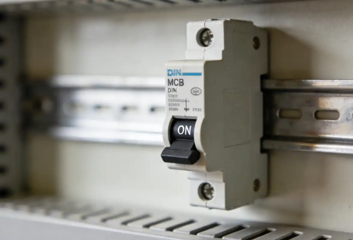
How to Test a Circuit Breaker With a Multimeter
A multimeter can provide a useful clue. It cannot certify a breaker. Learn which results matter, why continuity and voltage are different tests, and when exposed-panel work must stop.
A multimeter checks a condition—not the whole breaker
On an isolated electromechanical breaker in its prescribed test state, a qualified person can use continuity or resistance mode to see whether the contact path appears open or closed. Under a separate, approved live-work procedure, a voltage reading may help locate the boundary between a source problem, a breaker problem, and a downstream problem.
A beep can show that the meter's small internal current found a path. A voltage display can show the electrical potential between two approved points at that moment. Neither result proves that the breaker will carry rated load, trip on time, operate every pole together, detect an arc or ground fault, or interrupt its marked short-circuit current.
This guide is deliberately conceptual. It does not provide universal probe locations because panel construction, source arrangement, voltage, grounding, and breaker design change the safe test points.

Decide who should act before choosing the meter mode
Owning a multimeter does not make someone qualified for exposed electrical work. A qualified person is trained for the specific equipment and hazard. That includes recognizing live parts, determining nominal voltage, choosing protection, and using test equipment safely.
In a U.S. workplace, OSHA requires an energy-control process and verification at the parts to which workers will be exposed. These rules do not create a homeowner test procedure, but the principle is universal: a handle, status light, remote receptacle, or non-contact indicator is not proof that panel parts are safe to touch.

Observe without opening the panel
Record the affected loads, visible label, trip indication, odor, sound, recent weather, and what was running. Unplug accessible loads only when this can be done safely.
Do not remove the deadfront, touch the breaker to judge heat, or place probes inside the panel.Choose the correct diagnostic path
Identify every source, use the site procedure, isolate and secure energy where required, verify at each point of exposure, and follow the exact panel, breaker, and meter instructions.
Voltage diagnosis and de-energized continuity are different work states. Never mix their meter modes.Test the protection system
Trip curves, electronic trip units, sensors, stored-energy mechanisms, insulation, and critical switchgear may require OEM software, DLRO, injection equipment, or authorized field service.
A handheld DMM is not a substitute for a controlled breaker-performance test.Ask one precise question at a time
“Test the breaker” is too broad. Contact state, source voltage, trip timing, insulation, fault interruption, and panel compatibility are separate questions. This table keeps a narrow result from becoming a broad—and unsafe—conclusion.
| Question | What a DMM may indicate | What it cannot prove | Right test level |
|---|---|---|---|
| Is an isolated contact path open or closed? | Continuity or resistance behavior in a known de-energized, isolated test state. | Trip calibration, loaded contact heating, common operation of every pole, fault interruption, or overall serviceability. | Qualified person using the exact breaker and site procedure. |
| Is expected supply voltage available? | Voltage at an approved point during a controlled live diagnosis. | That the breaker is healthy; source, neutral, feeder, termination, or load faults may create the same symptom. | Qualified person under the electrical-safety program. |
| Will the breaker trip at the correct current and time? | Nothing conclusive. | Thermal, magnetic, or electronic trip performance and coordination. | OEM test kit or controlled primary/secondary injection as specified. |
| Is insulation healthy? | An ordinary DMM does not establish insulation health. | Dielectric condition, insulation resistance at the specified test voltage, or safe isolation of connected electronics. | Approved insulation tester, isolation plan, and product procedure. |
| Is a GFCI, AFCI, RCD, or RCBO function healthy? | A meter may support related circuit diagnosis. | The protective function described by the device standard and instructions. | Use the exact marked test function and OEM procedure; escalate abnormal results. |
| Can the breaker interrupt the available fault current? | Nothing. Never create a fault to find out. | Interrupting rating or end-equipment short-circuit suitability. | Verify markings, certification, available-fault-current study, and assembly data. |
Continuity is not capacity. A beep means only that the isolated path conducted the meter's small test current under that setup. It does not show that the path can carry normal current without excessive heat.
De-energized continuity and live voltage are not interchangeable
The safest mistake to avoid is changing the dial without changing the work state. Continuity mode applies a small internal signal. Voltage mode measures a live electrical condition. Each needs a different plan.
Contact-state check
The component must be isolated from every source and from circuit paths that could distort the reading. A qualified person verifies absence of voltage at the actual exposure points before resistance or continuity mode is used.
- Use the exact OEM test state and approved test points.
- Confirm the meter, leads, and continuity function first.
- Interpret ON, OFF, and tripped behavior in the context of that breaker design.
- Exclude parallel loads, auxiliaries, shared wiring, and alternate sources.
Source and fault-boundary check
A qualified person may use voltage readings to distinguish an unavailable source from a breaker, termination, neutral, control, or downstream problem. Exposed energized work requires the approved risk controls.
- Know the nominal voltage, source topology, and grounding system.
- Use the correct function, jacks, meter category, leads, probes, and protection.
- Choose test points from the actual drawings and equipment instructions.
- Treat every result as one piece of evidence, not a verdict.
What common patterns may suggest—and what remains unknown
These patterns are for a qualified, isolated test condition. “OL” often means open or over-range in the selected mode. It does not automatically mean the breaker failed.
| Qualified test pattern | Limited interpretation | Still rule out | Decision |
|---|---|---|---|
| Open in OFF/tripped; closed in ON | The basic isolated contact-state behavior appears consistent with the handle state. | Trip accuracy, contact heating, multi-pole common operation, downstream fault, and panel compatibility. | Do not call the breaker “good” from this result alone. |
| Remains open in its prescribed ON test state | An internal contact or operating-mechanism problem is possible. | Meter and lead fault, wrong test state, auxiliary paths, and incomplete isolation. | Keep out of service until the result is confirmed and the OEM action is known. |
| Unexpected continuity in OFF/tripped | A parallel path, setup issue, or device fault is possible. | Backfeed, connected loads, shared conductors, electronics, and whether every pole is isolated. | Stop and resolve the topology; do not assume the breaker welded closed. |
| Source condition is abnormal | The problem may be upstream or source-related. | Service, feeder, source transfer, fuse, neutral, phase loss, PV, generator, battery, or UPS paths. | Expand the diagnosis beyond the breaker. |
| Source appears normal; load stays dead | The breaker or termination may need more diagnosis, but the fault can be downstream. | GFCI/RCD, open conductor, neutral, control device, receptacle, connection, or failed load. | Locate the fault boundary before replacing parts. |
The meter and every accessory form one safety system
Choose the category and voltage rating for the actual measurement location. A distribution point may demand a different measurement category from a protected electronic circuit. The weakest meter, lead, probe, adapter, fuse, or setup controls the system.
- Inspect insulation, shrouds, finger guards, connectors, probe tips, case, display, and battery condition.
- Confirm the function, range, jacks, lead arrangement, internal fuse, and manufacturer instructions.
- Use a documented method to prove the tester. Many programs use a live-dead-live sequence.
- Remove damaged, unmarked, mismatched, or wrongly rated accessories from service.
A zero display from an unproven instrument may mean zero voltage—or a failed meter, damaged lead, wrong jack, wrong function, or poor connection. The applicable procedure determines how the tester is proven before and after the measurement.
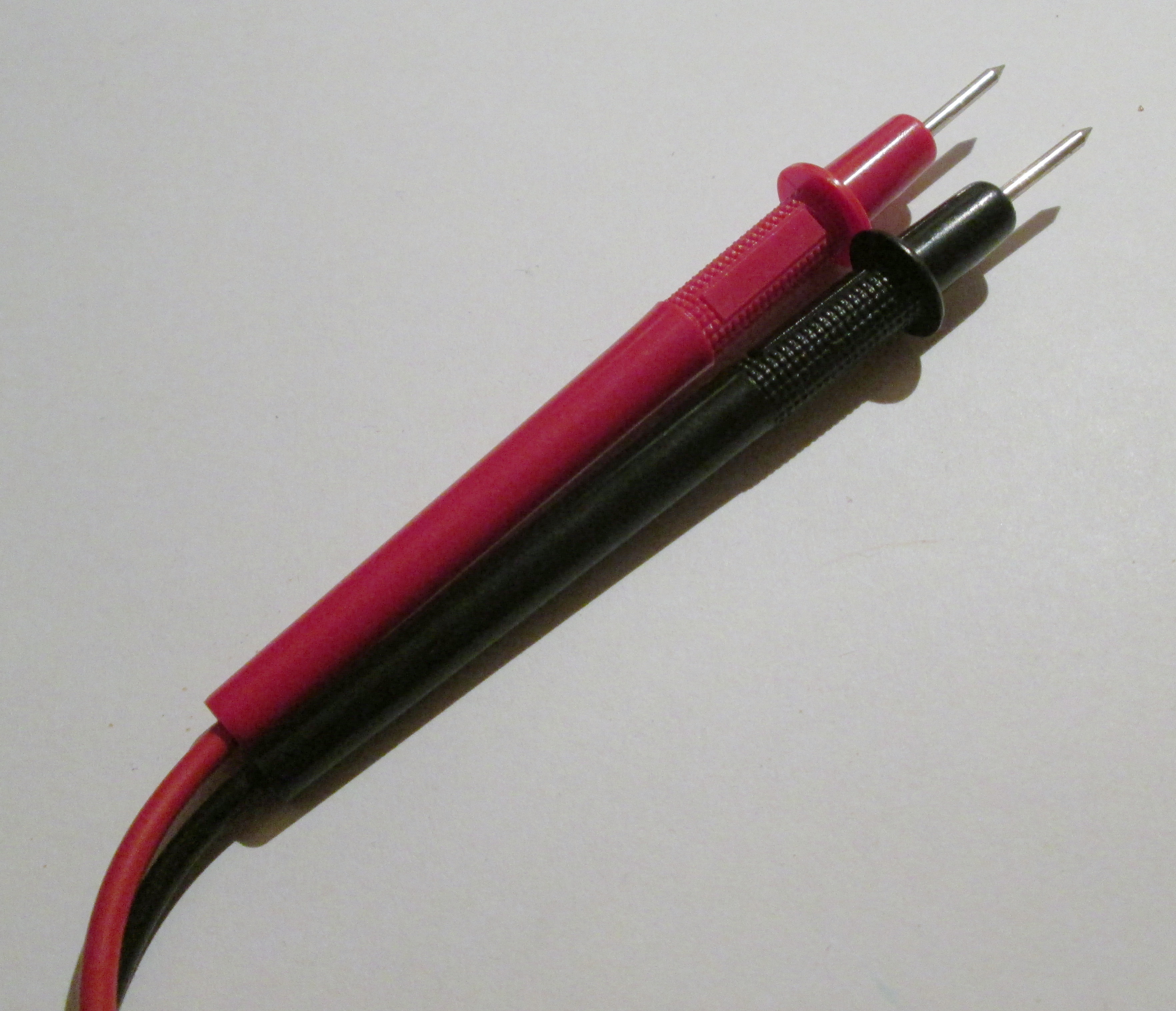
One multimeter method does not fit every breaker
A small branch breaker, thermal-magnetic MCCB, electronic-trip MCCB, and air circuit breaker have different mechanisms, accessories, diagnostics, maintenance boundaries, and test equipment.
Owner access stays outside
Normal user interaction is limited to visible labeling, the handle, and any marked user TEST function described in the manual.
Terminal testing behind the deadfront is qualified-person work.MCB / branch deviceDMM shows contact state only
A de-energized reading may indicate an open or closed path. Trip verification needs the published curve and controlled high-current method.
Do not infer thermal or magnetic performance from continuity.Professional testUse event data and OEM tools
Trip indication, settings, sensors, actuator, latch, firmware, and event logs can require software or dedicated primary/secondary injection.
Each test validates a different part of the protection chain.Model-specificTest a system, not two contacts
Drawout position, stored energy, interlocks, auxiliary circuits, insulation, trip unit, mechanism, and multi-pole operation may all matter.
Use the exact commissioning and maintenance guide.Specialist scopeCompare SENTOP’s miniature circuit breakers, molded-case circuit breakers, and air circuit breakers for product-family context. Testing, maintenance, and replacement must follow the exact catalog number.
Use the test that matches the protection question
A DMM is not a small trip tester. Critical breakers may require controlled current, dedicated resistance measurement, insulation test voltage, OEM diagnostics, or a full protection study.
| Tool or method | Question it can help answer | Main limit | Typical owner |
|---|---|---|---|
| DMM continuity / resistance | Does an isolated, verified de-energized path appear open or closed? | No trip curve, insulation proof, loaded contact performance, or fault-interruption evidence. | Qualified person following OEM instructions. |
| DMM voltage mode | Is expected voltage present at an approved point in a controlled diagnosis? | A reading does not identify the complete root cause. | Qualified person under the energized-work procedure. |
| DLRO / micro-ohmmeter | Does contact resistance meet a defined model-specific field criterion? | Requires controlled current, connection method, temperature context, and acceptance data. | Maintenance or field-service specialist. |
| Insulation-resistance tester | Does isolated insulation meet the specified test method? | The test voltage can damage connected electronics or trip units if the isolation plan is wrong. | Qualified test specialist. |
| Secondary injection / OEM kit | Does the electronic trip unit, actuator, and latch respond to a simulated input? | May not test integral current transformers or the full primary path. | OEM-trained or authorized service. |
| Primary injection | Does more of the sensor-to-trip chain follow the published time-current behavior? | Requires an isolated breaker, controlled low-voltage high current, heat management, and precise procedure. | Specialist test organization. |
A five-stage no-guesswork workflow
Screen for danger
Keep clear of smoke, arcing, odor, abnormal noise, visible heat damage, water, or multiple-circuit loss.
Outcome: emergency or qualified-service path if any red flag appears.Record the event
Note affected loads, visible labels, trip indication, operating equipment, weather, outage history, and alternate sources.
Outcome: evidence preserved before any reset or disassembly.Reduce accessible causes
Unplug or switch off reachable plug-in loads only when no fixed wiring or enclosure needs to be opened.
Outcome: safer triage without panel entry.Choose test level
Qualified personnel decide whether the case needs isolated contact state, live voltage diagnosis, thermal review, insulation test, or injection.
Outcome: one method tied to one question.Repair and document
Confirm the root cause and exact compatible replacement before installation, commissioning, and closeout records.
Outcome: protection restored—not simply the handle reset.Do not buy a breaker from one reading—or from physical fit
A replacement must match the panelboard or switchgear, system voltage and frequency, AC or DC duty, poles, protection function, available fault current, interrupting rating, terminals, conductor, accessories, and applicable certification.
Send the complete duty, not only the amp rating
SENTOP can help narrow a low-voltage protection BOM and provide product documents. Field diagnosis, replacement approval, installation, testing, coordination, and local acceptance remain the responsibility of the qualified project team.
Clear answers before anyone opens a panel
The safest answer is often about the work boundary, not the meter dial.
Can I test a circuit breaker without opening the panel?
Usually not at the breaker contacts. Relevant parts are often behind the deadfront, and removing it can expose energized conductors. A building user can record visible labels and symptoms with the cover closed. A qualified person decides whether an isolated contact-state test or controlled live diagnosis is appropriate.
Should I use volts or ohms to test a breaker?
They answer different questions. Ohms or continuity applies only to an isolated, verified de-energized path. Voltage mode belongs to an approved live diagnosis by a qualified person. Never use resistance or continuity where voltage may be present.
Does a continuity beep prove the breaker is good?
No. It shows that the isolated test path conducted the meter's small current under that setup. It does not prove rated-load performance, correct trip timing, common multi-pole operation, arc or ground-fault sensing, insulation, or fault interruption.
Does OL mean the breaker failed?
Not by itself. OL normally means open or over-range in the selected resistance or continuity context. That is expected with an isolated breaker in OFF or tripped state. In the prescribed ON test state, the setup, leads, isolation, parallel paths, and breaker design still need to be checked before replacement.
Why is the handle ON while the outlet or machine is dead?
The breaker may not be the cause. A local GFCI or RCD, open connection, neutral issue, failed control, damaged conductor, unavailable source, or failed load can produce the same symptom. Locate the fault boundary before changing the breaker.
Can a multimeter test a GFCI, AFCI, RCD, or RCBO breaker?
A DMM may support circuit diagnosis, but it does not replace the protective-device test specified by the manufacturer. Use the exact marked TEST function and instructions. If the response is abnormal, do not bypass the protection or install a standard breaker in its place.
Can I test a breaker by adding load until it trips?
No. Never create an overload, short circuit, or ground fault. Proper trip testing uses an isolated device, controlled specialist equipment, the exact time-current curve, and trained personnel. Repeated or incorrect injection can also damage some breakers.
Can I replace it with any breaker that fits and has the same amps?
No. Physical fit and ampere rating do not prove compatibility. Confirm the exact panel approval, voltage, AC or DC duty, poles, frequency, protection function, available fault current, interrupting rating, terminals, and certification.
Do PV, batteries, generators, UPS, or transfer switches change the test?
Yes. They can add alternate sources, stored energy, backfeed, automatic controls, and DC circuits. Utility loss or an open normal breaker may not remove every source. Use the source inventory and manufacturer-approved isolation procedure.
Technical references
- OSHA 1910.333 — Selection and use of work practices: de-energization, verification, backfeed, and exposed energized work.
- OSHA 1910.332 — Training: task-specific qualified-person training in U.S. workplaces.
- OSHA interpretation — panelboard line-side exposure: supply-side parts can remain energized after a disconnect is open.
- OSHA interpretation — verification at exposed parts: remote indicators do not replace direct verification of the relevant circuit elements.
- Fluke — continuity testing with a multimeter: de-energized use, isolated paths, and meter-dependent indications.
- Fluke — absence-of-voltage testing: tester verification and live-dead-live principle.
- Fluke — multimeter safety guide: measurement categories, ratings, functions, and test-system selection.
- UL Solutions — Molded Case Circuit Breaker Marking and Application Guide: test functions, AC/DC markings, interrupting ratings, and replacement compatibility.
- UL Solutions — Panelboards Guide: panelboard use, markings, and breaker application context.
- Eaton — primary versus secondary injection testing of MCCBs: purpose, coverage, and limitations of specialist tests.
- Schneider Electric — contact resistance testing and performance: why resistance alone is not a breaker health verdict.
- Schneider Electric — EasyPact MVS breaker tests: model-specific separation of continuity, insulation, mechanism, and automatic trip-curve tests.
