
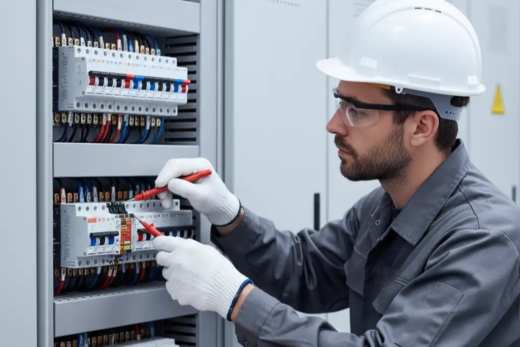
You can clean and check wiring terminals on your circuit breaker safely. Use the right tools and follow safety steps. Regular care keeps your electrical system working well. It helps you avoid common dangers:
- Electrical fires can start from old or broken wiring.
- Bad connections may cause shocks and damage things.
- Early checks help you find problems and save money.
Always wear safety gear. Call a professional if you feel unsure.
Key Takeaways
- Always turn off the power first before you start. This keeps you safe from shocks and burns.
- Wear the right safety gear like insulated gloves and safety glasses. These protect you while you clean and check the terminals.
- Clean and check your circuit breaker terminals every 2 to 5 years. This helps stop rust and keeps your electrical system safe.
- After cleaning, put a thin layer of electrical grease on the terminals. This keeps out water and stops rust, so it is easier to take care of later.
- If you smell something burning or feel heat, call a licensed electrician right away. This helps you stay safe from danger.
Circuit Breaker Safety
Electrical Hazards
You must turn off the power before you start. This keeps you safe from electrical hazards. If you forget, you could get hurt badly. Some dangers near circuit breaker wiring terminals are:
- Burns from touching electricity
- Electrocution
- Arc flash electric shock
- Fires or explosions
- Other serious injuries
You might also have problems like not enough insulation, circuit breaker failure, or broken appliances. Using extension cords the wrong way and not taking care of things can make these risks worse. Always make sure the power is off before you touch any wires or terminals.
Tip: Use a voltage tester or non-contact voltage tester to check that the power is off before you start.
Safety Gear and Tools
Wearing safety gear helps protect you from getting hurt. You should wear insulated gloves and safety glasses every time you work with electrical panels. These protect your hands and eyes from shocks and flying bits.
Important tools for cleaning and checking circuit breaker wiring terminals are:
- Multimeter and clamp meter for measuring voltage or current safely
- Non-contact voltage tester to check for live wires
- Insulation tester to check system health
- Insulated screwdrivers for safe handling
- Wire brush and fine sandpaper for cleaning terminals
- Electrical contact cleaner to remove dirt and corrosion
- Electrical grease to stop future corrosion
Keep these tools close and use them when you need them. The right tools help you work safer and better.
When to Call a Professional
Sometimes you need an expert. Call a licensed electrician if you see:
- Flickering lights or breakers that trip a lot
- A burning smell near the electrical panel
- Problems with the panel you cannot fix
Licensed electricians know how to keep your circuit breaker system safe and follow the rules. They do regular checks and tests. Home electrical repairs need certified professionals to keep things safe and legal. If you feel unsure or see damage, do not try to fix it yourself.
Cleaning and Inspecting Terminals
Power Off and Access Panel
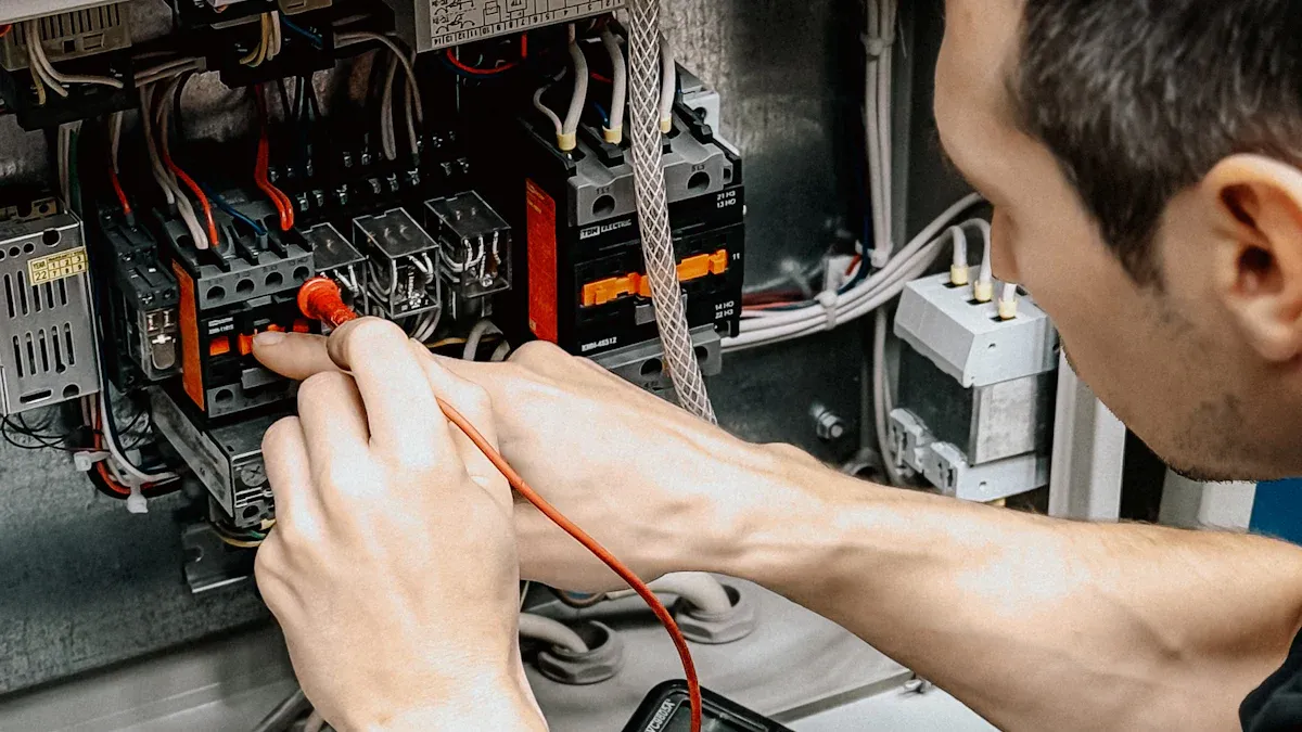
You must always start by making sure the power is off before you touch any part of the circuit breaker. Follow these steps to power down and safely access the panel:
- Use a voltage tester to check that no voltage is present on the load side.
- Follow your facility’s lockout procedures if you have them.
- Close all downstream circuits except for the main disconnect or circuit breaker.
- Use an ohm meter to check for shorts on the disconnected load side.
- Check phase-to-phase and phase-to-ground impedance. You want at least 1 Mega Ohm to ground and more than 2 ohms phase to phase.
- If you find a short, open half of the switches, fuses, and breakers. Repeat this step until you find the problem.
- Check the impedance between different power sources. It should be greater than 1 Mega Ohm.
- Close the panel door for arc flash protection.
- Only turn the main breaker back on after you finish all cleaning and inspection steps.
Tip: Always double-check with a non-contact voltage tester before you begin any work.
Visual Inspection
After you open the panel, look closely at the wiring terminals. Use a flashlight to help you see small details. Here are signs that show you may have a problem:
- Burn marks or discoloration around the circuit breaker or wires
- Corrosion or rust on metal parts
- Loose wires or screws
- Unusual smells, like burnt plastic or wiring
- Frequent tripping of the circuit breaker
If you see any of these signs, you need to clean or repair the area before using the circuit breaker again.
Cleaning Methods
Cleaning the wiring terminals helps prevent future problems. Gather your materials first:
- Wire brush or abrasive pad
- 220-grit sandpaper
- Soft, lint-free cloth
- Electrical contact cleaner (choose nonflammable and safe for plastics)
- Deoxidizing compound
Follow these steps:
- Make sure the power is off.
- Use a wire brush or abrasive pad to gently remove corrosion from the terminals.
- For stubborn spots, use 220-grit sandpaper. Rub lightly to avoid damaging the metal.
- Wipe away dust and debris with a soft cloth.
- Spray a small amount of electrical contact cleaner on the terminals. Make sure the cleaner is nonflammable and does not harm plastic or rubber parts.
- Let the terminals dry completely before moving to the next step.
Note: Do not use too much contact cleaner. Too much can leave residue and attract dirt. Always work in a well-ventilated area and wear your safety gear.
Applying Electrical Grease
After cleaning, you should protect the terminals from future corrosion. Electrical grease forms a barrier that keeps out moisture and air. This helps stop rust and corrosion from forming again. It also makes future maintenance easier and protects against things like battery acid and moisture.
- Apply a thin layer of electrical grease, such as NO-OX-ID A-Special, to all metal connection points.
- Focus on aluminum connectors, as they are more likely to corrode.
- Do not use too much grease. A thin layer works best and avoids attracting dirt.
Re-Inspection
Before you close the panel, check your work. Make sure everything is tight and safe:
- Inspect the tightness of each terminal. Use the right screwdriver to check each screw.
- If you find a loose screw, tighten it carefully. Do not use too much force, or you could damage the terminal.
- Make sure you applied only a thin layer of grease. Wipe away any extra.
- Exercise the circuit breaker by switching it on and off a few times. This helps spread the grease and keeps the contacts working well.
Tip: Regular re-inspection keeps your system safe. Here is a guide for how often you should check your circuit breaker terminals:
| Condition | Recommended Interval |
|---|---|
| Newer Homes (10-15 years) | Every 3 to 5 years |
| Older Homes (pre-1980s) | Every 2 to 3 years |
By following these steps, you help your circuit breaker last longer and work more safely. Avoid common mistakes like using too much cleaner, using rough tools, or skipping safety gear. Careful cleaning and inspection protect your home and your electrical system.
Reassembly and Power Restoration
Reattaching Panel Covers
After you finish cleaning and inspecting, you need to put the panel cover back on safely. Follow these steps:
- Turn off the main breaker and all other breakers to lower the risk of shock.
- Gather all screws before you handle the cover.
- Ask someone to help hold the cover if it feels heavy or awkward.
- Keep the cover door open so you can line it up with the breakers.
- Hold the cover straight and use your arms to place it over the panel. Avoid tilting.
- Use your forearm to steady the cover while you match up the screw holes.
- Insert screws into opposite corners first. Tighten them by hand.
- Once all screws are in, use a screwdriver to tighten each one. Rotate from screw to screw to keep the cover even.
Tip: Always check that the cover sits flat and does not pinch any wires.
Restoring Power
You must restore power with care to avoid accidents. Take these precautions:
- Stand a safe distance from the panel.
- Do not look directly at the panel when turning breakers on.
- Shield your body in case an arc flash happens.
- Never touch exposed wires or conductors.
- Turn off or unplug any devices connected to the circuits.
- If you see water near the breaker box, do not approach or touch the panel.
Turn on the main breaker first, then switch on each circuit one at a time. Watch for any sparks, noises, or smells.
Testing Circuit Breaker
Testing ensures your circuit breaker works as it should. Use these steps:
- Use a multimeter. Place one probe on the input terminal and the other on the output terminal. A low resistance means the breaker works.
- Test the breaker by switching it on and off. Make sure it trips when overloaded.
- Check all settings to match the original design.
- Perform electrical tests for insulation and contact pressure.
- If you have access, check the torque specifications on the panel label or breaker. Use a calibrated torque tool if needed.
| Testing Method | Description |
|---|---|
| Check settings | Make sure all settings match the design. |
| Electrical tests | Test insulation, contact pressure, and interrupting power. |
| Operational functions | Confirm the breaker trips for overcurrent. |
If the circuit breaker fails any test, inspect it closely. Call a professional if you find problems or suspect miswiring.
Troubleshooting Issues
Persistent Problems
Sometimes, you may notice that your circuit breaker keeps tripping or does not work right, even after cleaning and inspection. You can follow these steps to find the cause:
- Unplug or turn off all devices that use the same circuit. This helps you see if one device causes the problem.
- Check the wattage of each device. Add up the total load on the circuit.
- Move some devices to other circuits if you can. This can help balance the load and stop the breaker from tripping.
- If the problem does not go away, call a licensed electrician. They have the tools and training to find hidden issues.
If you keep having trouble, do not ignore it. Persistent problems can mean a bigger issue in your electrical system.
Signs of Damage
You should look for clear signs that show your circuit breaker or wiring terminals need repair or replacement. Watch for these warning signs:
- You feel heat coming from the breaker. This can mean the device is faulty.
- You smell something burning near the electrical panel. This may mean the wiring or insulation is overheating.
- You see scorch marks around the breaker or outlets. This shows melted wiring and a possible fire risk.
If you notice any of these signs, stop using the circuit and get help right away.
When to Seek Help
Some problems need a professional. You should call an electrician if you see:
- The breaker trips when nothing is plugged in. This can mean a short circuit or damaged wiring.
- Your electrical panel is over 25 years old or is a brand known for problems.
- You plan to add high-demand appliances and need new circuits.
- You see burning, arcing, or sparking. These are serious faults.
- You feel unsure or nervous about doing electrical work.
Regular maintenance helps prevent many issues. Insurance may not cover damage if you neglect routine care. Always keep your system in good shape to protect your home and your coverage.
Cleaning and checking your circuit breaker often keeps it safe. This helps your circuit breaker work well for a long time. When you use the right tools and follow safety steps, you protect your home. You also avoid spending lots of money on repairs. Doing regular maintenance gives you many good things. You can spot weak spots in your electrical system early. You fix problems before they get worse. You also learn more about what your electrical system needs. This helps your equipment last longer. Make a plan to check your circuit breaker often. Call an expert if you notice any warning signs.
FAQ
How often should you clean circuit breaker terminals?
Check and clean your circuit breaker terminals every 3 to 5 years if your home is newer. For older homes, do this every 2 to 3 years. Checking often helps stop corrosion and keeps your electrical system safe.
What safety gear do you need for cleaning circuit breaker terminals?
Wear insulated gloves and safety glasses. These keep your hands and eyes safe from electric shock and flying pieces. Always put on your safety gear before you open the panel.
Can you use water to clean circuit breaker terminals?
Do not use water to clean circuit breaker terminals. Water can cause short circuits and hurt your electrical system. Use a contact cleaner made for electrical parts instead.
What should you do if you find corrosion on a terminal?
Use a wire brush or fine sandpaper to clean off corrosion. Put a thin layer of electrical grease on after you clean. If the corrosion is really bad, call a licensed electrician for help.
Is it safe to clean circuit breaker terminals without turning off the power?
No, you must turn off the power before you clean or check circuit breaker terminals. Use a voltage tester to make sure the power is off. This keeps you safe from electric shock.
See also
How to Replace a Circuit Breaker Safely in 2025
Do I need to turn off the solar panels during cleaning?
Maintenance and inspection checklist for solar combiner box
Step-by-Step Guide to Replacing Miniature Circuit Breakers
How to Identify and Fix Air Circuit Breaker Malfunctions

Discover more from SENTOP Electrical Co., Ltd
Subscribe to get the latest posts sent to your email.
