
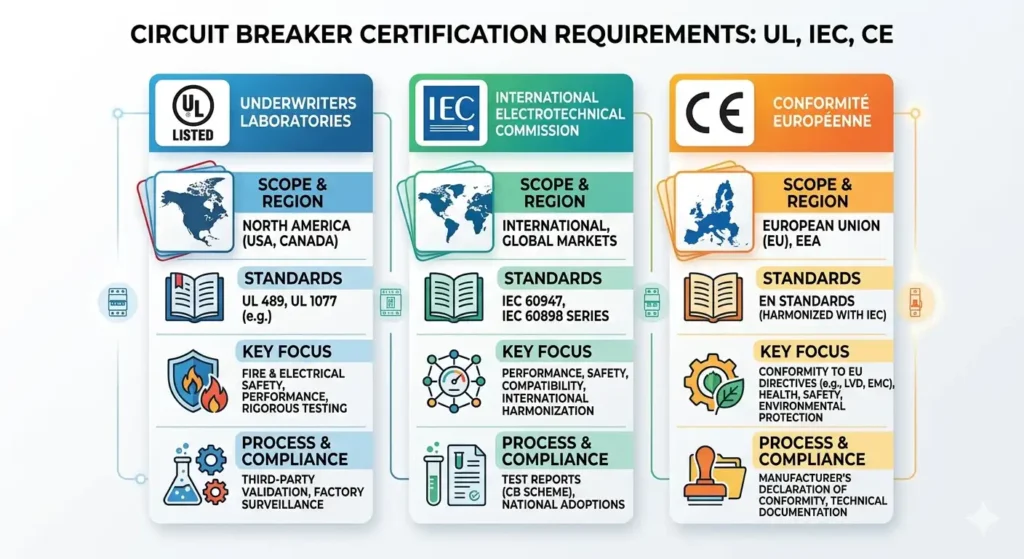
Circuit breaker certification is not a single process — it’s three fundamentally different systems with distinct philosophies, testing methods, and market implications. UL tests against North American safety expectations using 40°C ambient assumptions. IEC follows internationally harmonized protocols at 30°C reference. CE marking isn’t even a certification at all — it’s a manufacturer’s self-declaration under European directives. Getting these distinctions wrong costs manufacturers months of delays and tens of thousands of dollars in redundant testing. This guide breaks down exactly what each framework demands, where they diverge, and how to build a certification strategy that doesn’t waste your engineering budget.
What Circuit Breaker Certification Actually Requires
At its core, circuit breaker certification means a qualified third party (or in the case of CE, the manufacturer itself) has verified that the device meets specific safety and performance benchmarks. The breaker must interrupt fault currents without causing fire, electric shock, or mechanical failure. It must do this repeatedly, under defined conditions, with predictable behavior.
That sounds straightforward. It isn’t.
The three dominant frameworks — UL, IEC, and CE marking — each define “safe” and “performing” differently. They use different test setups, different ambient temperature baselines, different sample sizes, and different documentation structures. A circuit breaker that passes IEC 60947-2 with flying colors can fail UL 489 testing on the same day, in the same lab. Not because it’s unsafe, but because the standards measure different things in different ways.
Here’s a quick-reference comparison to orient you before we dive deeper:
| Parameter | UL (North America) | IEC (International) | CE Marking (Europe) |
|---|---|---|---|
| Type | Third-party certification | Third-party testing to standard | Self-declaration of conformity |
| Key Standards | UL 489, UL 1077 | IEC 60947-2, IEC 60898-1 | EN 60898, EN 60947 (harmonized) |
| Ambient Temp Reference | 40°C open air | 30°C reference | Follows IEC harmonized standards |
| Factory Audits | Required (ongoing) | Depends on scheme | Not mandatory for most breakers |
| Market Access | USA, Canada (with CSA) | 120+ countries | EU, EEA, Turkey |
| Typical Timeline | 4–8 months | 3–6 months | Self-paced (weeks to months) |
| Approximate Cost | $30,000–$80,000+ | $15,000–$50,000 | $5,000–$20,000 (testing + documentation) |
The cost ranges above fluctuate significantly based on breaker ratings, number of variants, and whether you’re testing a brand-new design or a derivative of an already-certified platform. Those numbers represent typical ranges for a single product family — not the full scope of a multi-market rollout.
UL Certification Standards for Circuit Breakers
UL certification for circuit breakers revolves around three primary standards, and confusing them is one of the most expensive mistakes a manufacturer can make.
UL 489 covers industrial circuit breakers — the workhorses installed in panelboards, switchboards, and industrial control panels across North America. This is the standard most manufacturers target first, and it’s the most demanding of the three.
UL 1077 addresses supplementary protectors. These are not branch circuit breakers. They provide supplementary overcurrent protection within equipment and cannot serve as the sole means of branch circuit protection. The testing requirements are less rigorous than UL 489, but the product carries a more limited scope of application. Many manufacturers mistakenly pursue UL 1077 thinking it’s a cheaper path to market, then discover their customers’ panel builders require UL 489 Listed devices.
UL 489B covers molded-case switches — devices that look like circuit breakers but lack overcurrent trip capability. They’re used for motor disconnect and isolation applications.
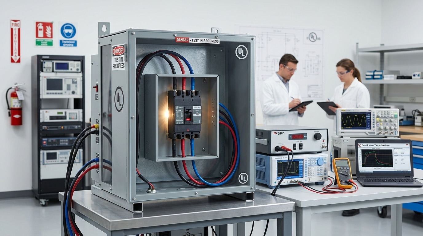
What UL Actually Tests
The testing sequence under UL 489 is extensive. Here are the critical tests that trip up manufacturers most often:
- Overload testing: The breaker must trip within specified time windows at 135% and 200% of rated current. UL calibrates at 40°C ambient in open air — a detail that changes thermal performance calculations significantly compared to IEC.
- Short-circuit testing: Conducted at the rated interrupting capacity (e.g., 10kA, 14kA, 65kA). The breaker must safely interrupt the fault without expelling flame, molten metal, or creating conditions for continued arcing. Post-test, it must still provide basic insulation integrity.
- Endurance testing: Thousands of operating cycles at rated current. For a 100A breaker, expect 4,000 operations minimum — 2,000 electrical, 2,000 mechanical. The contacts must show acceptable wear without welding or excessive resistance increase.
- Dielectric withstand: High-voltage impulse and sustained voltage tests verify insulation integrity. Creepage and clearance distances must meet UL’s spacing requirements, which differ from IEC tables.
- Temperature rise: Every terminal, conductor, and adjacent surface is measured under full-load conditions. Terminal temperatures exceeding 50°C rise above ambient (for certain terminal types) mean failure.
The UL Listing Process and Factory Inspections
Getting through the lab is only half the battle. UL requires ongoing factory inspections through its Follow-Up Service (FUS) program. A UL inspector visits your manufacturing facility — typically quarterly, sometimes unannounced — to verify that production units match the tested samples. They check materials, components, assembly processes, and calibration equipment.
This is where “UL Listed” diverges from “UL Recognized.” A Listed product is a complete, standalone device ready for end-use installation. A Recognized component is intended for use within a larger Listed assembly. Recognition involves less rigorous conditions of acceptability but restricts how the product can be marketed and installed. If you’re selling circuit breakers to panel builders or distributors, you almost certainly need UL Listing, not Recognition.
Common UL Testing Pitfalls
After watching dozens of manufacturers go through this process, the failures cluster around a few predictable issues. Terminal temperature rise is the number one killer — especially when manufacturers design for IEC’s 30°C ambient and then discover their thermal margins evaporate at UL’s 40°C baseline. Short-circuit tests reveal inadequate arc chute designs that worked fine at lower fault levels but fail at the rated interrupting capacity marked on the product. And documentation gaps — missing material certifications, incomplete wiring diagrams, or vague manufacturing procedures — can stall a project for months even after all physical tests pass.
IEC Standards and Testing Protocols for Circuit Breakers
IEC standards form the backbone of circuit breaker certification outside North America. The International Electrotechnical Commission (IEC) publishes the standards; national bodies adopt and sometimes modify them.
Three standards matter most:
IEC 60947-2 covers industrial circuit breakers (the IEC equivalent of UL 489). This is the standard for devices used in industrial installations, rated above 125A or intended for systems with high prospective fault currents.
IEC 60898-1 addresses circuit breakers for household and similar installations — typically devices up to 125A used in residential and light commercial distribution boards. This is the standard behind the miniature circuit breakers (MCBs) installed in consumer units worldwide.
IEC 61009 covers residual current-operated circuit breakers with integral overcurrent protection (RCBOs), combining MCB and RCD functionality in a single device.
Utilization Categories and Breaking Capacities
IEC 60947-2 introduces a concept that doesn’t exist in UL: utilization categories.
Category A breakers have no intentional short-time delay. They trip immediately on fault detection. Most molded-case circuit breakers (MCCBs) fall here.
Category B breakers are designed with a deliberate short-time withstand capability, allowing them to coordinate with downstream devices in a selective protection scheme. They must withstand the rated short-time current (Icw) for a specified duration — typically 0.5 or 1 second — without tripping. This is critical for main incoming breakers in industrial switchgear.
IEC also distinguishes between two breaking capacity ratings that confuse many engineers:
- Icu (rated ultimate short-circuit breaking capacity): The maximum fault current the breaker can interrupt. After this test, the breaker is not required to carry rated current — it just needs to survive.
- Ics (rated service short-circuit breaking capacity): The fault current level after which the breaker must still function normally. Ics is expressed as a percentage of Icu (25%, 50%, 75%, or 100%). A breaker with Ics = 100% Icu can interrupt its maximum rated fault and immediately return to full service. This is the number that actually matters for real-world reliability.
Trip Curve Classifications
Under IEC 60898-1, MCBs are classified by their instantaneous trip characteristics:
- Type B: Trips between 3× and 5× rated current. Used for resistive loads and long cable runs.
- Type C: Trips between 5× and 10× rated current. The most common selection for general-purpose circuits with moderate inrush.
- Type D: Trips between 10× and 20× rated current. Selected for motor loads, transformers, and other high-inrush applications.
UL doesn’t use this B/C/D classification system. UL 489 breakers have their own trip characteristics defined by different curves, which is one reason direct cross-referencing between UL and IEC breakers requires careful engineering analysis.
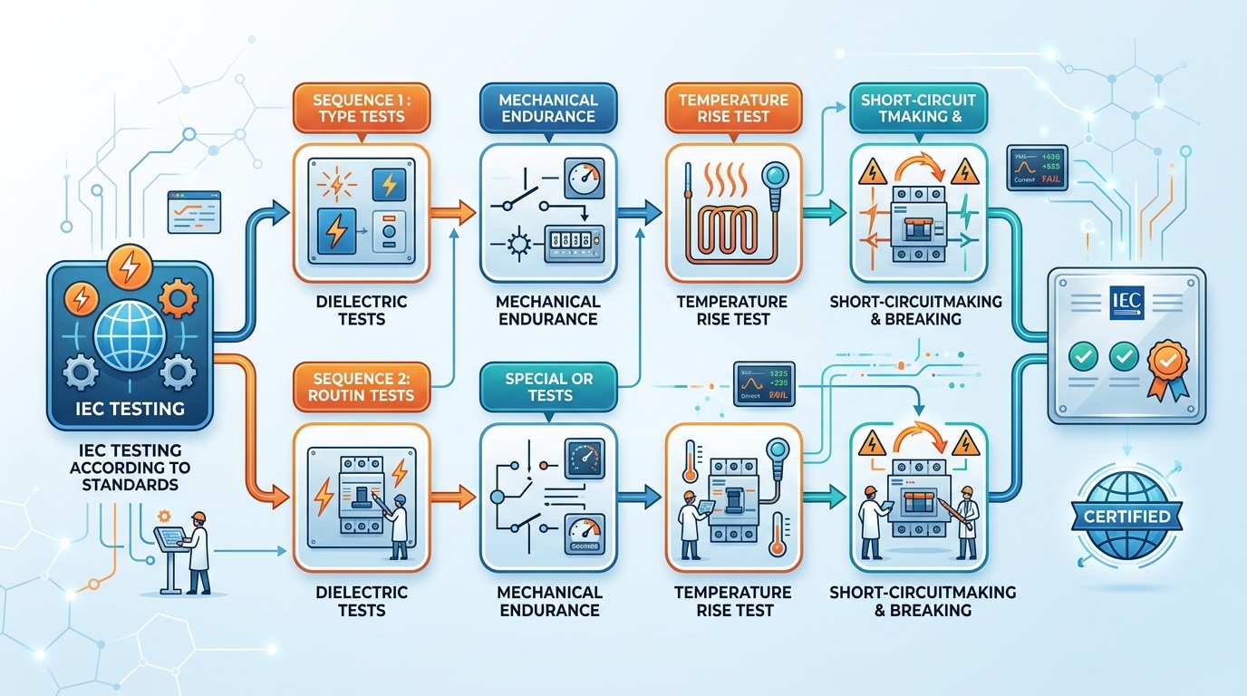
IEC Testing Sequence
One fundamental difference: IEC testing follows a defined test sequence where the same samples undergo multiple tests in a prescribed order. The breaker that survived the overload test is the same one subjected to the short-circuit test. UL, by contrast, often uses fresh samples for different test groups. This sequential approach in IEC means cumulative stress effects are captured — a breaker weakened by overload testing must still pass the short-circuit test that follows. It’s arguably a more realistic simulation of field conditions.
CE Marking Requirements and the Low Voltage Directive
Here’s the misconception that wastes the most money: CE marking is not a certification.
Read that again. CE is a manufacturer’s self-declaration that a product complies with all applicable European directives. No government agency tests your breaker. No third-party lab is legally required to approve it (for most circuit breakers). You, the manufacturer, assess conformity, compile a technical file, write a Declaration of Conformity, affix the CE mark, and take legal responsibility.
The relevant directive for circuit breakers is the Low Voltage Directive (LVD) 2014/35/EU, which covers electrical equipment designed for use with voltage ratings between 50V and 1000V AC (or 75V to 1500V DC). Circuit breakers fall squarely within this scope.
Essential Requirements
The LVD doesn’t specify exact test procedures. Instead, it defines “essential health and safety requirements” — protection against electrical shock, thermal effects, mechanical hazards, and fire. To demonstrate compliance, manufacturers typically test against harmonized standards:
- EN 60898-1 (the European adoption of IEC 60898-1 for household MCBs)
- EN 60947-2 (the European adoption of IEC 60947-2 for industrial breakers)
Testing to a harmonized standard creates a “presumption of conformity” with the directive. You can technically demonstrate compliance through other means, but using harmonized standards is the path of least resistance and the one that holds up best if challenged by market surveillance authorities.
Technical File and Declaration of Conformity
Your technical file must include:
- General product description and intended use
- Design drawings and manufacturing process descriptions
- A list of harmonized standards applied (fully or partially)
- Test reports demonstrating compliance with those standards
- Risk assessment addressing the LVD’s essential requirements
- Operating instructions and safety information
The Declaration of Conformity (DoC) is a structured document identifying the product, the manufacturer, the applicable directives, the harmonized standards used, and a legally binding signature from an authorized representative. The European Commission’s CE marking guidance provides templates and detailed requirements for the DoC format.
When Do You Need a Notified Body?
For most circuit breakers under the LVD alone, a Notified Body is not required. Self-assessment is sufficient. However, if your breaker falls under additional directives — such as the ATEX Directive for explosive atmospheres or certain EMC requirements that can’t be self-assessed — third-party involvement becomes mandatory.
Even when not legally required, many manufacturers voluntarily engage a Notified Body or an accredited test laboratory to generate test reports. Why? Because market surveillance authorities in EU member states can request your technical file at any time. Having test reports from a recognized lab like TUV, DEKRA, or Bureau Veritas carries far more weight than in-house testing data if your compliance is ever questioned.
The bottom line: CE marking is legally the easiest path to market. But “easy” doesn’t mean “low risk.” If your self-declared breaker causes an incident in the field, the legal liability falls entirely on you, with no third-party certification body sharing that burden.
Key Differences Between UL and IEC Testing Approaches
This is where most global manufacturers get burned. The standards look similar on the surface — both test overload, short-circuit, endurance, and dielectric performance. But the devil is in the methodology, and those methodological differences produce materially different results.
Ambient Temperature Baseline
This single difference causes more certification failures than any other factor.
UL calibrates thermal trip performance at 40°C ambient in open air. IEC uses a 30°C reference temperature, typically measured inside an enclosure. That 10°C gap means a breaker designed to trip at exactly 135% of rated current under IEC conditions may trip prematurely under UL conditions — or, if the thermal element is adjusted to compensate, it may trip too slowly at the IEC reference point.
For manufacturers designing a single hardware platform for both markets, this requires either adjustable thermal calibration or separate thermal trip elements for UL and IEC variants. Neither option is free.
Short-Circuit Test Procedures
UL short-circuit tests typically use a specific test circuit configuration with defined power factor (or X/R ratio) values. IEC 60947-2 specifies power factor values that differ from UL’s requirements at certain voltage and current levels. The result: identical breakers may experience different peak let-through currents during testing, even at the same rated fault level.
IEC also requires the O-t-CO test sequence (Open — time delay — Close-Open) as part of the breaking capacity verification. The breaker interrupts a fault, waits a defined interval, then recloses onto a second fault and must interrupt again. UL has its own reclosing test requirements, but the timing and sequence differ.
Detailed Comparison of Test Parameters
| Test Parameter | UL 489 | IEC 60947-2 |
|---|---|---|
| Ambient calibration temp | 40°C open air | 30°C reference (in enclosure) |
| Overload trip test | 135% and 200% of rated current | 1.05× (non-trip), 1.3× (trip) of rated current |
| Short-circuit power factor | Varies by rating (e.g., 0.45–0.50 typical) | Varies by rating (e.g., 0.25 for Icu ≤ 25kA at 415V) |
| Test sample reuse | Fresh samples per test group | Sequential testing on same samples |
| Breaking capacity rating | Single AIR (Ampere Interrupting Rating) | Icu and Ics (ultimate and service) |
| Endurance (100A breaker) | 4,000 operations (2,000 elec + 2,000 mech) | Varies by utilization category |
| Marking requirements | UL-specific format with AIR, voltage, wire range | IEC-specific symbols (Icu, Ics, trip curve letter) |
| Wire termination testing | UL-specific wire pull and torque tests | IEC terminal strength tests (different force values) |
Why Cross-Certification Isn’t Automatic
A breaker certified to IEC 60947-2 cannot be sold in the United States as a branch circuit breaker without UL 489 Listing. Period. The National Electrical Code (NEC) and local Authorities Having Jurisdiction (AHJs) require UL or equivalent NRTL listing. Similarly, a UL 489 Listed breaker doesn’t automatically satisfy IEC requirements for markets that mandate IEC compliance.
Some testing laboratories offer combined test programs that evaluate against both standards simultaneously, sharing common test setups where possible. This can save 20–30% on total testing costs compared to running two completely separate programs. But the breaker design itself must accommodate both sets of requirements — which often means designing to the more stringent requirement in each category.
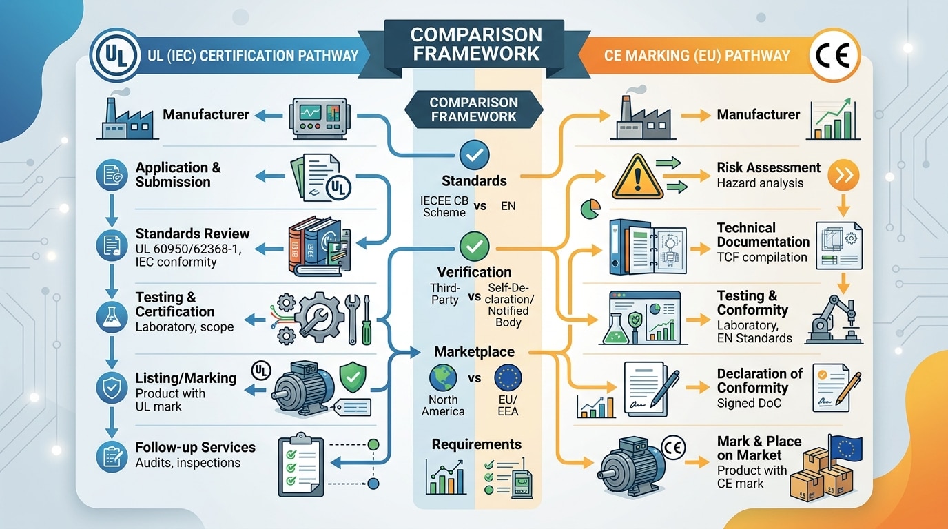
The Certification Process Step by Step
Whether you’re pursuing UL, IEC, or CE compliance, the process follows a broadly similar arc. The details and timelines differ, but the phases are consistent.
Phase 1: Pre-Compliance Assessment (2–4 Weeks)
Before spending a dollar on formal testing, conduct a gap analysis. Compare your breaker’s design specifications against the target standard’s requirements. Pay special attention to creepage and clearance distances, material flammability ratings (UL 94 V-0 for most components), and terminal design. Many manufacturers skip this step and discover fundamental design issues during formal testing — at $500+ per hour of lab time.
Pre-compliance testing at an independent lab costs a fraction of formal certification testing and identifies showstoppers early. Budget $3,000–$8,000 for a thorough pre-compliance evaluation.
Phase 2: Laboratory Selection and Application (1–2 Weeks)
For UL certification, you’ll work directly with UL or a UL-recognized testing facility. For IEC testing, select a laboratory accredited under ISO/IEC 17025 — look for NVLAP or A2LA accreditation in North America, or UKAS/DAkkS accreditation in Europe. For CB Scheme reports (more on this later), the lab must be an IECEE-recognized National Certification Body (NCB) or CB Testing Laboratory (CBTL).
The application package typically includes product specifications, circuit diagrams, material declarations, assembly drawings, and a description of all variants you want covered under the certification.
Phase 3: Sample Submission (1–2 Weeks)
Labs require multiple samples — typically 15 to 30 units depending on the standard and the number of ratings being tested. These must be production-representative samples, not hand-built prototypes. UL is particularly strict about this: if your submitted samples differ from production units in any material way, the certification is invalid.
Phase 4: Testing (6–16 Weeks)
This is the longest phase and the most variable. A straightforward MCB evaluation against IEC 60898-1 might complete in 6–8 weeks. A complex MCCB evaluation against UL 489 at multiple voltage and current ratings can stretch to 16 weeks or more, especially if failures require design modifications and retesting.
Lab scheduling also impacts timelines. Major testing facilities like UL, TUV, and Intertek often have 4–8 week backlogs. Booking lab time early — even before your samples are finalized — can save months.
Phase 5: Factory Audit (UL Only, 1–2 Weeks)
UL sends an inspector to your manufacturing facility to verify that production processes, quality controls, and incoming material inspections match what was described in the application. The initial factory inspection must pass before UL issues the certification. Subsequent inspections occur quarterly.
Phase 6: Certification Issuance and Ongoing Compliance
Once testing and audits pass, you receive your certification (UL Listing, CB Test Certificate, or compile your CE technical file). But certification isn’t a one-time event. UL requires ongoing factory surveillance. CB Certificates have a defined validity period. CE technical files must be updated whenever the product or applicable standards change.
Realistic total timelines from application to market:
- UL 489 Listing: 4–8 months
- IEC CB Scheme Certificate: 3–6 months
- CE marking (with voluntary third-party testing): 2–4 months
- CE marking (self-assessment with in-house testing): 4–8 weeks
Regional and Market-Specific Certification Requirements
UL, IEC, and CE cover the largest markets, but they’re far from the complete picture. Manufacturers targeting global distribution face a patchwork of national certifications, each with its own bureaucratic quirks.
Major Regional Certifications
- CCC (China Compulsory Certification): Mandatory for circuit breakers sold in China. Based on GB standards (which are largely adopted from IEC with modifications). Requires testing at a CNCA-designated laboratory and factory inspection by a Chinese certification body. Timeline: 3–6 months. The process has improved significantly in recent years but still involves more administrative complexity than most Western certifications.
- KC (Korea Certification): Mandatory for electrical equipment in South Korea. Based on Korean Industrial Standards (KS), which align closely with IEC. Testing must be performed at a KOLAS-accredited lab.
- PSE (Product Safety Electrical Appliance): Required for Japan. Based on JIS standards with specific Japanese deviations from IEC. The diamond-shaped PSE mark requires third-party testing; the circular PSE mark allows self-declaration for lower-risk categories.
- BIS (Bureau of Indian Standards): Mandatory for circuit breakers in India under the BIS compulsory registration scheme. Based on IS standards (adopted from IEC). Requires testing at a BIS-recognized lab and factory inspection.
- EAC (Eurasian Conformity): Required for Russia, Belarus, Kazakhstan, Armenia, and Kyrgyzstan. Replaced the old GOST-R mark. Based on IEC-aligned technical regulations with additional documentation requirements in Russian.
- CSA (Canadian Standards Association): For the Canadian market. CSA C22.2 No. 5.1 is the Canadian equivalent of UL 489. Many manufacturers pursue dual UL/CSA certification (cUL mark) through a single test program.
The CB Scheme: Your Shortcut to Multi-Market Certification
The IECEE CB Scheme is the single most valuable tool for manufacturers pursuing global certification. Here’s how it works:
You test your circuit breaker once at an IECEE-recognized CB Testing Laboratory against the relevant IEC standard. The lab issues a CB Test Report and CB Test Certificate. You then submit that CB report to national certification bodies in your target markets. Each national body reviews the report, evaluates any national deviations (documented in the CB report), and — if satisfied — issues their national certification without requiring full retesting.
This can reduce per-country certification costs by 40–70% and compress timelines by months. The catch: national deviations still apply. China, India, and South Korea all have national deviations from IEC standards that may require supplementary testing. But even with deviations, the CB Scheme eliminates the bulk of redundant testing.
Strategic Approach to Global Certification
Start with IEC testing and a CB Scheme certificate. This gives you the broadest base for international market access. Layer on UL/CSA for North America as a parallel workstream. Use the CB report to fast-track national certifications in your priority export markets. Don’t try to certify for every market simultaneously — prioritize based on revenue potential and customer demand, then expand the certification portfolio over time.
Common Compliance Failures and How to Avoid Them
Most certification failures are predictable. After enough test cycles, patterns emerge clearly. Here are the failure modes that account for the vast majority of rejected circuit breaker submissions.
Creepage and Clearance Distances
This is the most common design-related failure. Creepage (the shortest path between two conductors along a surface) and clearance (the shortest distance through air) must meet minimum values specified in the standard, based on voltage rating, pollution degree, and material group. Designers frequently underestimate the impact of pollution degree 3 (typical for industrial environments) or forget to account for material group classifications that affect creepage requirements.
Fix: Verify creepage and clearance at the PCB layout and mechanical design stage, not after tooling is cut. Use IEC 60947-1 Annex G or UL 489 Table 7.1 (depending on target standard) as your reference. Account for worst-case tolerance stackups in your mechanical assemblies — the minimum distance on the drawing isn’t the minimum distance in production.
Terminal Temperature Rise
The second most frequent failure. Terminals must not exceed specified temperature rise limits under full rated current. The limits vary by terminal type and material — for example, a bare copper terminal has different limits than a tin-plated terminal or one connected to insulated conductors. Manufacturers designing to IEC’s 30°C ambient often find their thermal margins disappear when tested at UL’s 40°C baseline.
Fix: Run thermal simulations early. Better yet, build a prototype and run a full thermal test at your own facility before submitting to the certification lab. If you’re targeting both UL and IEC, design your thermal performance to pass at 40°C ambient — you’ll have margin to spare for IEC testing.
Marking Durability
This one surprises manufacturers who focus entirely on electrical performance. Both UL and IEC require that product markings (ratings, manufacturer identification, certification marks) remain legible after exposure to solvents, abrasion, and normal handling. The test involves rubbing the marking with a cloth soaked in specific solvents — typically water, isopropyl alcohol, and sometimes petroleum-based solvents.
Ink-jet printed markings fail this test regularly. Pad-printed markings with inadequate curing fail. Even laser-engraved markings can fail if the engraving depth is insufficient on certain plastic materials.
Fix: Use laser engraving with verified depth parameters, or pad printing with proper ink chemistry and curing profiles validated against the solvent rub test before submission. Request the specific solvent rub procedure from your target standard and run it in-house first.
Endurance Test Failures
After thousands of operating cycles, contact resistance increases, springs fatigue, and mechanical linkages develop play. The most common endurance failure mode is contact welding — the contacts fuse together under electrical load and the breaker can no longer open. This typically indicates insufficient contact pressure, inadequate contact material selection, or contact bounce during closing operations.
Fix: Select contact materials appropriate for the rated current and expected duty cycle. Silver-cadmium oxide (AgCdO) and silver-tin oxide (AgSnO2) are standard choices for different current ranges. Verify contact pressure specifications and spring force retention after the full endurance cycle during your own development testing.
Incomplete Technical Documentation
Not a test failure per se, but a project killer nonetheless. Missing material certifications (UL 94 flammability ratings for plastic components, CTI values for insulating materials), incomplete wiring diagrams, vague manufacturing procedures, or absent quality control documentation can delay certification by months. UL is particularly demanding — they want to see material traceability from raw material supplier through to finished product.
Fix: Build your technical file in parallel with product development, not after testing. Create a documentation checklist aligned with your target standard’s requirements and assign ownership for each deliverable. Collect material certifications from suppliers proactively — don’t wait until the lab asks for them.
Frequently Asked Questions About Circuit Breaker Certification
Can one circuit breaker carry both UL and IEC certification?
Yes, and many global manufacturers do exactly this. A single breaker design can be tested against both UL 489 and IEC 60947-2, receiving dual certification. The key challenge is designing the thermal trip element to satisfy both UL’s 40°C open-air calibration and IEC’s 30°C reference temperature. Some manufacturers use adjustable thermal elements; others produce separate calibration variants for each market. Dual-certified products typically carry both the UL Listing mark and the IEC CB Scheme certificate, enabling sale across North America and IEC-adopting countries from a single hardware platform.
How long does UL certification take for circuit breakers?
Expect 4 to 8 months from initial application to UL Listing issuance, assuming no major test failures requiring design changes. The breakdown is roughly: 1–2 weeks for application processing, 4–8 weeks for lab scheduling backlog, 8–16 weeks for testing, and 1–2 weeks for factory audit and final review. If your breaker fails any critical test, add 4–8 weeks for redesign and retesting per failure. Pre-compliance testing can identify issues early and significantly reduce the risk of delays during formal evaluation.
What is the difference between UL Listed and UL Recognized?
UL Listed means the product has been evaluated as a complete, standalone device suitable for end-use installation. It carries the full UL Listing mark and can be installed directly by electricians and contractors. UL Recognized means the component has been evaluated for use as part of a larger Listed system or assembly — it carries the UR (UL Recognized) mark and comes with specific “Conditions of Acceptability” that define how it must be integrated. For circuit breakers sold as standalone products to panel builders, distributors, or end users, UL Listing is almost always the required path. Recognition is appropriate for OEM components embedded within another manufacturer’s Listed equipment.
Does CE marking require third-party testing?
For most circuit breakers under the Low Voltage Directive (2014/35/EU), third-party testing is not legally required. CE marking is a self-declaration of conformity — the manufacturer assesses compliance, compiles a technical file, and signs a Declaration of Conformity. However, voluntary third-party testing from an accredited laboratory significantly strengthens your compliance position. If market surveillance authorities question your CE marking, a test report from a recognized body like TUV or DEKRA provides far stronger evidence than in-house test data. Most serious manufacturers opt for third-party testing despite the lack of legal mandate.
How often must circuit breaker certifications be renewed?
UL Listing does not have a fixed expiration date — it remains valid as long as you maintain the Follow-Up Service agreement and pass quarterly factory inspections. However, if UL updates the standard (e.g., a new edition of UL 489), you may need to demonstrate compliance with the updated requirements within a transition period. CB Scheme certificates typically have a 5-year validity period, after which renewal testing may be required. CCC certificates for China require annual surveillance audits and periodic retesting. CE technical files must be updated whenever the product design changes or when harmonized standards are revised.
What happens if a certified product design changes?
Any change to a certified product — materials, components, dimensions, manufacturing process, or supplier — must be evaluated for impact on certification. For UL, you submit a “variation” or “alteration” request describing the change. UL engineering reviews it and determines whether additional testing is needed. Minor changes (e.g., a cosmetic color change to a non-functional component) may be approved without testing. Major changes (e.g., a different contact material or modified arc chute geometry) will require partial or full retesting. For CE marking, you must update your technical file and reassess whether the change affects compliance with the essential requirements. Failing to report changes to your certification body is a serious compliance violation that can result in certification revocation.
How much does circuit breaker certification cost?
Costs vary dramatically based on breaker type, number of ratings, and target markets. Rough ranges for a single product family: UL 489 Listing runs $30,000–$80,000+ including testing, factory audit, and initial Follow-Up Service fees. IEC testing with a CB Scheme certificate costs $15,000–$50,000. CE marking with voluntary third-party testing runs $5,000–$20,000. National certifications (CCC, KC, BIS) add $8,000–$25,000 each, though CB Scheme reports can reduce these significantly. A comprehensive global certification program for a new MCCB platform — covering North America, Europe, China, and 3–4 additional national markets — can easily exceed $150,000. Pre-compliance testing ($3,000–$8,000) is the best investment you can make to avoid multiplying these costs through retesting.
Building a Strategic Certification Plan for Your Circuit Breakers
If you take one thing from this entire article, make it this: design for certification from day one, don’t retrofit compliance into a finished design.
Retrofitting is how you end up redesigning arc chutes after tooling is already cut, or discovering that your PCB layout violates creepage requirements after 10,000 units are already in inventory. Every certification failure that requires a design change costs 5–10× more than addressing the same issue during the initial design phase.
The Recommended Certification Sequence
For manufacturers targeting global markets, this sequence maximizes efficiency and minimizes redundant testing:
- Start with IEC testing and a CB Scheme certificate. This gives you the broadest international base. Choose a CBTL that also holds UL recognition — some labs can run IEC and UL tests in parallel on shared setups, saving significant time and cost.
- Pursue UL/CSA certification in parallel. If North America is a priority market, don’t wait for IEC completion. Start the UL application process simultaneously. Design your breaker to meet UL’s more demanding thermal requirements from the outset — this ensures IEC compliance comes easily.
- Use the CB report to fast-track national certifications. Submit your CB test report to CCC, KC, BIS, and other national bodies as needed. Address national deviations with supplementary testing only where required.
- Compile your CE technical file using the IEC test reports. Since EN harmonized standards are adopted from IEC, your CB Scheme test data directly supports CE compliance. Add the risk assessment, Declaration of Conformity, and product documentation to complete the file.
Pre-Certification Checklist
Before engaging any testing laboratory, ensure you have the following ready:
- ☐ Complete product specifications (voltage ratings, current ratings, breaking capacities, trip characteristics for all variants)
- ☐ Mechanical drawings with tolerances, including creepage and clearance analysis
- ☐ Circuit schematics and wiring diagrams
- ☐ Bill of materials with material certifications (UL 94 ratings, CTI values, RTI ratings for all plastic components)
- ☐ Contact material specifications and supplier certifications
- ☐ Manufacturing process descriptions and quality control procedures
- ☐ 15–30 production-representative samples (confirm exact quantity with your lab)
- ☐ Pre-compliance test results identifying and resolving any design gaps
- ☐ Target market list with prioritized certification requirements
- ☐ Budget allocation covering testing, factory audits, retesting contingency (add 25–30% buffer), and ongoing surveillance fees
The Single Best Piece of Advice
Engage your target testing laboratory during the design phase, not after it. Most major labs — UL, TUV, Intertek, DEKRA — offer preliminary design review services. For a few thousand dollars, their engineers will review your drawings and flag compliance issues before you commit to tooling. This consultation alone has saved manufacturers hundreds of thousands of dollars in redesign and retesting costs.
Certification isn’t a bureaucratic hurdle to clear after product development. It’s a design input that belongs in your requirements specification from the first sketch. Treat it that way, and the process becomes predictable, manageable, and far less expensive than the alternative.
See also
Complete Guide to Choosing the Right ATS Class
Top 10 Most Reliable Terminal Block Manufacturers in China
A Practical Guide to Comparing IEC 60898-1 and IEC 60947-2 Standards
IEC and UL certification requirements for air circuit breakers
How to Avoid Common Errors in Terminal Block Certifications

Discover more from SENTOP Electrical Co., Ltd
Subscribe to get the latest posts sent to your email.
