
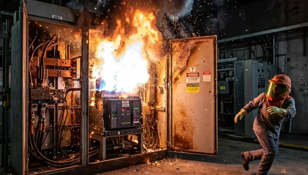
Arc flash incidents at circuit breakers release temperatures exceeding 35,000°F and generate blast pressures capable of throwing a worker across a room. Circuit breaker arc flash protection requirements are governed primarily by the NEC (NFPA 70), NFPA 70E, and IEEE 1584, and they mandate specific engineering controls, labeling, PPE protocols, and energy reduction methods to prevent catastrophic injuries. This guide breaks down every requirement you need to know, from code compliance to building a complete mitigation plan for your facility.
What Are Circuit Breaker Arc Flash Protection Requirements
An arc flash is an explosive release of energy caused by an electrical fault that ionizes the air between conductors or between a conductor and ground. At a circuit breaker, this can happen during switching operations, maintenance procedures, or when a fault occurs inside the equipment enclosure. The resulting plasma ball can reach temperatures four times hotter than the surface of the sun.
Circuit breaker arc flash protection requirements are the collection of codes, standards, and engineering practices that exist to minimize both the likelihood of an arc flash event and the severity of injury when one occurs. They cover three distinct domains:
- Equipment design and installation — governed by the National Electrical Code (NEC/NFPA 70)
- Workplace safety practices — governed by NFPA 70E
- Hazard analysis methodology — supported by IEEE 1584
These requirements exist because arc flash injuries remain one of the leading causes of workplace electrical fatalities. According to the Occupational Safety and Health Administration (OSHA), electrical hazards cause more than 160 fatalities and thousands of injuries annually in the United States. A significant portion of those incidents involve arc flash events at switchgear and panelboard locations where circuit breakers are the primary protective devices.
The regulatory framework doesn’t just suggest best practices. OSHA enforces compliance with NFPA 70E through its General Duty Clause, meaning facilities that ignore arc flash protection requirements face citations, fines, and — far worse — preventable injuries to their workers.
Key NEC and NFPA 70E Standards Governing Arc Flash Protection
Multiple standards work together to form the complete arc flash protection picture. Understanding which standard covers what — and where they overlap — is essential for compliance.
NEC Article 240: Overcurrent Protection
Article 240 establishes the fundamental requirements for overcurrent protective devices, including circuit breakers. It dictates how these devices must be rated, applied, and coordinated to clear faults quickly. Faster fault clearing directly reduces arc flash incident energy, which is why proper overcurrent protection is the first line of defense.
Section 240.87 specifically addresses arc energy reduction for circuit breakers rated 1200 amperes or higher. We’ll dig into this one deeply in the next section because it’s the code provision most directly tied to arc flash mitigation at the circuit breaker level.
NEC 110.16: Arc Flash Warning Labels
This section mandates that electrical equipment likely to require examination, adjustment, servicing, or maintenance while energized must be field-marked with a warning label. The label must warn qualified persons of potential arc flash hazards. The 2017 NEC revision expanded 110.16 to require labels that include nominal system voltage, available fault current, and clearing time — or the equivalent incident energy and arc flash boundary information.
NFPA 70E: Standard for Electrical Safety in the Workplace
While the NEC focuses on installation, NFPA 70E focuses on the people who work on or near energized equipment. It defines arc flash risk assessment procedures, approach boundaries, PPE requirements, and safe work practices. OSHA doesn’t directly adopt NFPA 70E as law, but routinely references it as the consensus standard for workplace electrical safety — and uses it as the benchmark when issuing citations.
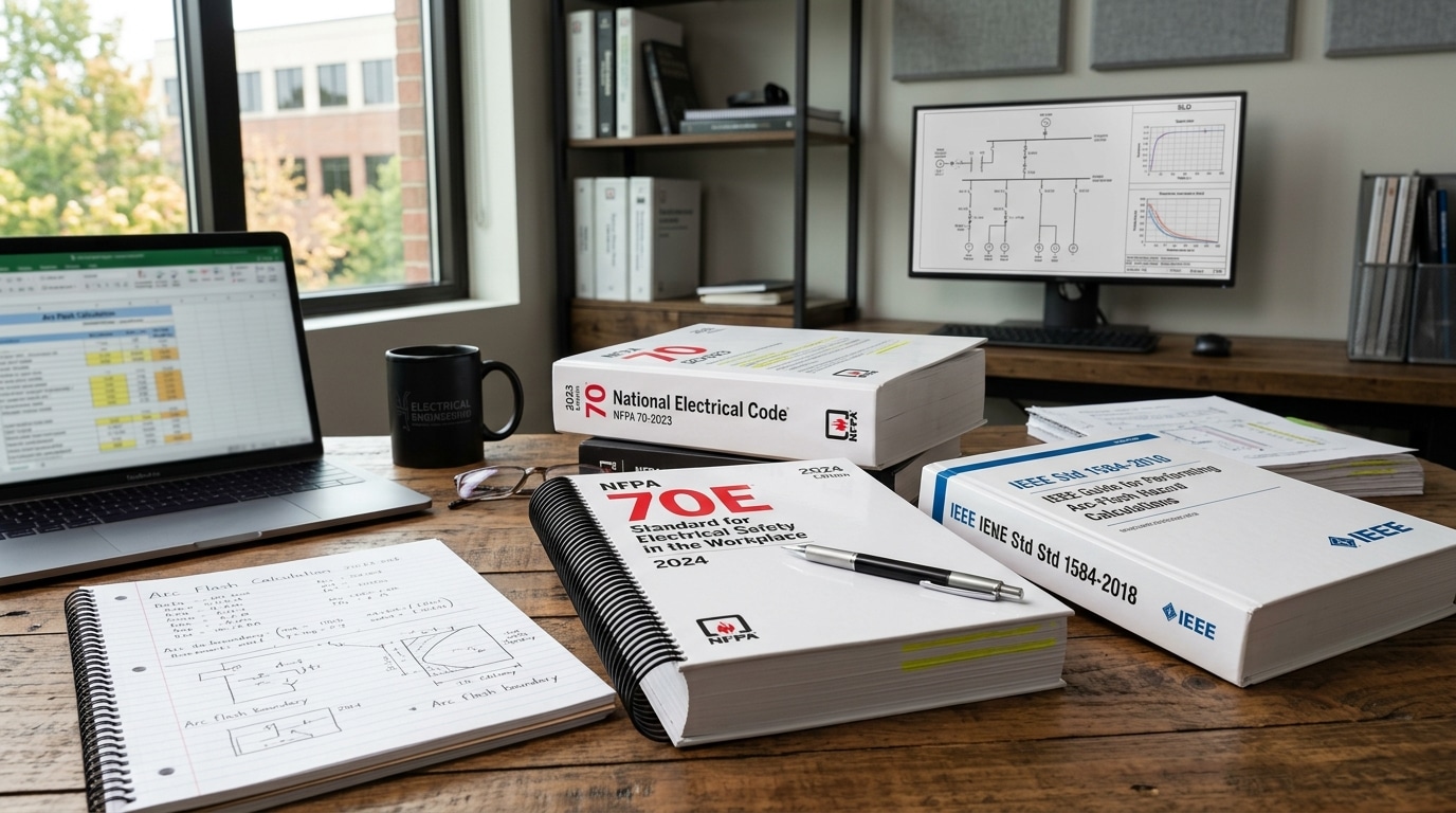
IEEE 1584: Guide for Performing Arc Flash Hazard Calculations
IEEE 1584 provides the mathematical models and empirical data used to calculate incident energy levels and arc flash boundaries. The 2018 edition significantly updated the calculation methodology, expanding the range of applicable voltages (208V to 15,000V), electrode configurations, and enclosure sizes. Any serious arc flash study relies on IEEE 1584 as its computational backbone.
Here’s how these standards interact in practice:
| Standard | Primary Focus | Key Arc Flash Provisions |
|---|---|---|
| NEC Article 240 | Overcurrent device installation | 240.87 arc energy reduction methods |
| NEC 110.16 | Equipment labeling | Arc flash warning label requirements |
| NFPA 70E | Workplace safety | Risk assessments, PPE, boundaries, safe work practices |
| IEEE 1584 | Hazard calculation | Incident energy and arc flash boundary formulas |
Missing any one of these creates a gap. A facility can have perfectly installed circuit breakers per the NEC and still be non-compliant if workers aren’t following NFPA 70E procedures or if labels are outdated.
NEC 240.87 and Arc Energy Reduction Requirements for Circuit Breakers
NEC 240.87 is the code section that most directly targets arc flash hazards at the circuit breaker itself. It applies to circuit breakers rated 1200 amperes or higher and requires that one or more approved methods of arc energy reduction be available on the equipment.
Why 1200 amps? Because at that current level and above, the available fault energy is typically high enough to produce incident energy levels that can cause severe or fatal burns. The code writers drew the line where the risk profile changes dramatically.
The Five Approved Methods Under 240.87
The code lists specific methods that satisfy the arc energy reduction requirement:
- Zone-selective interlocking (ZSI) — A communication scheme between upstream and downstream protective devices that allows the device closest to the fault to trip with minimal delay while upstream devices maintain coordination.
- Differential relaying — Uses current transformers on both sides of a protected zone. If current entering doesn’t equal current leaving, a fault exists within the zone and the relay trips the breaker instantaneously.
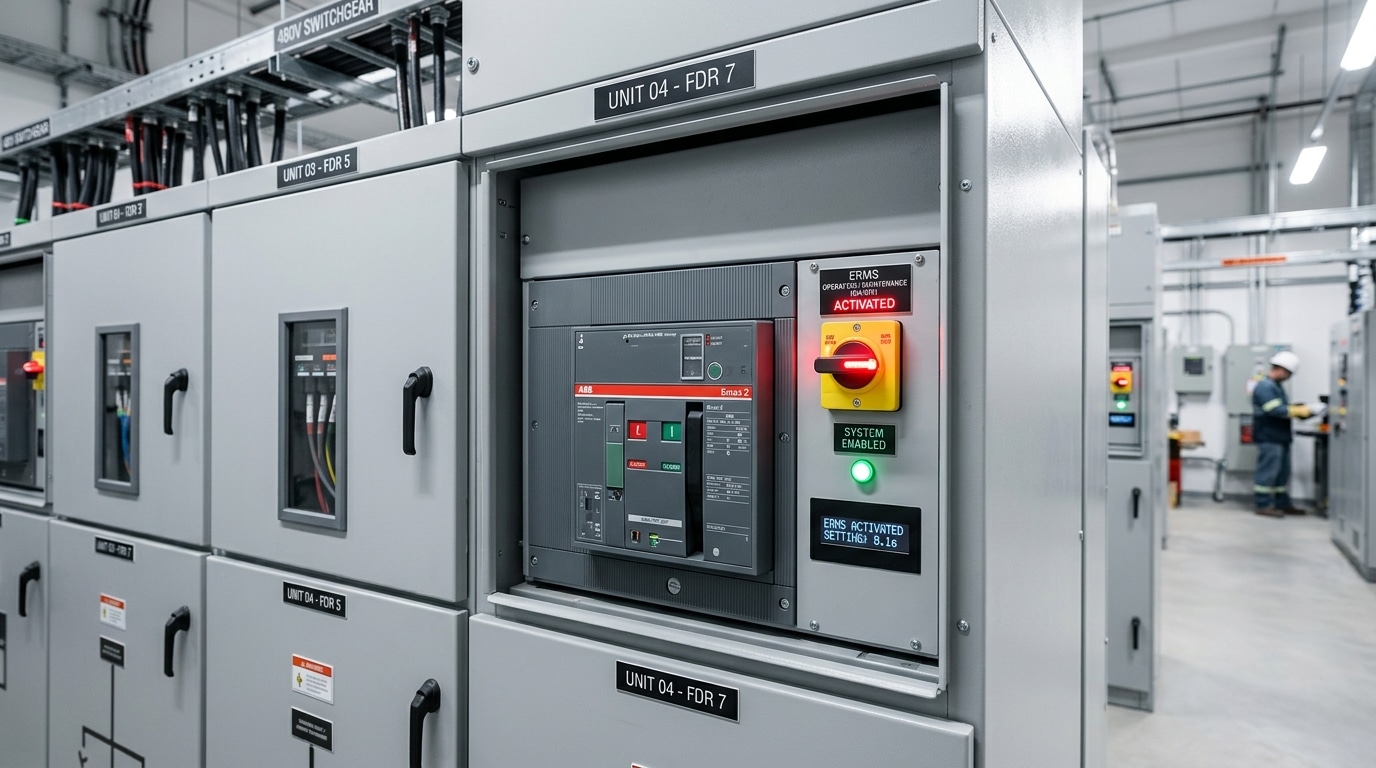
- Energy-reducing maintenance switching — A manually activated mode that temporarily reduces the breaker’s trip time during maintenance activities, then reverts to normal coordination settings when maintenance is complete.
- Energy-reducing active arc flash mitigation system — Uses light sensors, current sensors, or both to detect an arc flash event in real time and trip the breaker within milliseconds. Some systems achieve clearing times under 4 milliseconds.
- An approved equivalent method — The code leaves room for emerging technologies, provided they achieve comparable arc energy reduction and are accepted by the authority having jurisdiction (AHJ).
One thing many engineers overlook: 240.87 doesn’t require all five methods simultaneously. You need at least one. But the best practice — and what I’d recommend for any new installation — is to implement at least two complementary methods. ZSI paired with energy-reducing maintenance switching, for example, gives you both automated protection during normal operation and enhanced protection during the highest-risk activity: maintenance.
The single biggest factor in arc flash severity is clearing time. Every cycle (16.67 milliseconds at 60Hz) that a fault persists dramatically increases incident energy. The entire purpose of 240.87 is to get that clearing time as short as physically possible.
NFPA 70E Workplace Electrical Safety Requirements
The NEC tells you how to install equipment. NFPA 70E tells you how to keep people alive while working on it.
NFPA 70E’s arc flash provisions center on the concept of a risk assessment that must be performed before any worker approaches energized electrical equipment. This isn’t a one-time study that sits in a binder. It’s a process that must happen every single time someone opens an electrical panel or operates a circuit breaker under conditions that could expose them to an arc flash hazard.
Arc Flash Risk Assessment (Article 130.5)
The risk assessment must determine:
- Whether an arc flash hazard exists
- The appropriate safety-related work practices to use
- The arc flash boundary
- The PPE required for the task
- The tools and equipment necessary to perform the work safely
NFPA 70E gives you two paths for determining PPE: the incident energy analysis method (using IEEE 1584 calculations) or the PPE category method (using the tables in NFPA 70E Article 130.7). The incident energy analysis method is more precise and often results in lower PPE requirements for specific tasks because it accounts for the actual system parameters at each location. The table method is more conservative — it uses worst-case assumptions.
Approach Boundaries
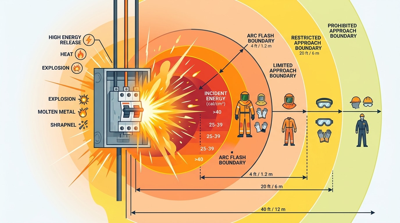
NFPA 70E defines three approach boundaries for shock protection and one for arc flash:
- Limited approach boundary — Only qualified persons may enter
- Restricted approach boundary — Additional shock protection measures required
- Prohibited approach boundary — Treated as direct contact with energized parts
- Arc flash boundary — The distance at which incident energy equals 1.2 cal/cm2 (the threshold for a second-degree burn on unprotected skin)
The arc flash boundary is the one most relevant to circuit breaker work. It can range from a few inches for a small 208V panelboard to over 40 feet for a large 480V switchgear lineup with high available fault current and slow clearing times. That’s not a typo. Forty feet. Which means an unprotected worker standing across the room could still receive second-degree burns.
How to Calculate Arc Flash Boundaries and Incident Energy Levels
Arc flash calculations aren’t something you eyeball. They require specific input data, validated calculation methods, and engineering judgment. IEEE 1584-2018 is the current standard methodology, and it represents a significant improvement over the earlier 2002 edition.
Key Input Variables
Every arc flash calculation requires these parameters for each circuit breaker location:
- Bolted fault current (kA) — The maximum available short-circuit current at the point of the potential arc flash. This comes from a short-circuit study of the electrical system.
- Clearing time (seconds) — How long the upstream protective device takes to interrupt the fault. This includes both the relay/trip unit operating time and the breaker’s mechanical opening time.
- Working distance (mm) — The distance from the potential arc source to the worker’s face and chest. Standard working distances are defined by equipment type: 455mm for panelboards, 610mm for low-voltage switchgear, 910mm for medium-voltage switchgear.
- Electrode configuration — The 2018 edition of IEEE 1584 introduced five electrode configurations (VCB, VCBB, HCB, VOA, HOA) that account for how conductors are oriented inside the enclosure. This matters enormously — a vertical configuration in a box (VCB) produces dramatically different incident energy than a horizontal open-air (HOA) configuration.
- Enclosure dimensions — Width, height, and depth of the equipment enclosure, because the enclosure focuses and amplifies the arc energy.
- Gap between conductors (mm) — The distance between the electrodes where the arc initiates.
The Calculation Process
At a high level, IEEE 1584 calculations follow this sequence:
- Determine the arcing current from the bolted fault current (the arc impedance reduces current below the bolted value)
- Use the arcing current to determine the protective device clearing time from its time-current characteristic curve
- Calculate the incident energy at the specified working distance
- Determine the arc flash boundary (the distance where incident energy drops to 1.2 cal/cm2)
A critical detail that gets missed: you must run calculations at both 100% and 85% of the available fault current. Why? Because a lower arcing current can actually result in higher incident energy if it falls into a slower region of the protective device’s time-current curve. The protective device might trip in 0.05 seconds at full fault current but take 0.5 seconds at 85% — and that tenfold increase in clearing time can double or triple the incident energy.
Most engineers use software tools like SKM Power Tools, ETAP, or EasyPower to perform these calculations across an entire facility. A manual calculation for a single point is feasible, but a typical industrial facility has hundreds of circuit breaker locations that each need individual analysis.
Approved Methods for Arc Energy Reduction in Switchgear and Panelboards
Reducing incident energy at circuit breaker locations comes down to one fundamental principle: reduce the time the arc persists. Every method recognized by NEC 240.87 achieves this in a different way, and each has distinct advantages and limitations.
Zone-Selective Interlocking (ZSI)
ZSI creates a communication link between circuit breakers at different levels of the electrical system. When a fault occurs, the breaker closest to the fault sends a restraint signal to upstream breakers, telling them to delay their trip. The downstream breaker then trips on its instantaneous setting — no intentional delay.
Advantage: Maintains coordination during normal faults while dramatically reducing clearing time at the fault location. No special sensors or additional equipment beyond the communication wiring.
Limitation: Only works between breakers that support ZSI communication. Requires compatible trip units. And if the communication link fails, the system defaults to normal time-delay coordination — meaning you lose the arc energy reduction benefit exactly when you might need it most.
Differential Relaying
This method compares current entering and leaving a protected zone. Any difference means current is flowing to a fault within that zone, and the relay trips the breaker instantaneously.
Advantage: Extremely fast and selective. Trips only for faults within the protected zone, so it doesn’t affect coordination with other devices.
Limitation: Requires current transformers on both sides of the protected zone, which adds cost and complexity. Most commonly used in medium-voltage applications and large low-voltage switchgear. Rarely practical for smaller panelboards.
Energy-Reducing Maintenance Switching
A manually activated setting that temporarily reduces the circuit breaker’s trip time. The worker switches the breaker to “maintenance mode” before beginning work, which overrides the normal time-delay settings and enables a faster trip.
Advantage: Simple, reliable, and doesn’t require any additional equipment beyond a trip unit that supports the feature. Gives workers direct control over their protection level.
Limitation: Only provides protection when someone remembers to activate it. If a worker forgets to flip the maintenance switch before opening the panel, they’re exposed to full incident energy. This is a human-factors problem that training alone doesn’t fully solve.
Energy-Reducing Active Arc Flash Mitigation Systems
These are the fastest-acting systems available. They use optical sensors (detecting the intense light of an arc), current sensors (detecting the overcurrent), or both in combination. When both conditions are detected simultaneously, the system trips the breaker in as little as 1-4 milliseconds.
Advantage: The most dramatic reduction in incident energy. Can reduce incident energy by 90% or more compared to standard protection. Always active — doesn’t depend on human action.
Limitation: Higher upfront cost. Requires proper commissioning and periodic testing. Optical sensors can potentially be triggered by external light sources if not properly installed, though modern systems with dual-sensing (light + current) virtually eliminate nuisance trips.
Instantaneous Trip Settings
Simply setting the circuit breaker’s instantaneous trip function to respond to the available arcing current at that location. If the arcing current exceeds the instantaneous pickup setting, the breaker trips without any intentional delay.
Advantage: No additional equipment or cost. Uses the breaker’s existing capability.
Limitation: May compromise selective coordination with downstream devices. If the instantaneous setting is too low, the upstream breaker may trip for downstream faults, causing unnecessary outages.
Arc Flash Labeling Requirements for Circuit Breaker Equipment
Labels are the visible, tangible proof that a facility takes arc flash protection seriously. They’re also one of the most commonly cited deficiencies during electrical safety audits.
What NEC 110.16 Requires
NEC 110.16(B) requires that equipment labels include:
- Nominal system voltage
- Arc flash boundary
- Available incident energy at the working distance, or the arc flash PPE category from NFPA 70E tables
- Date of the arc flash study (required by NFPA 70E, not explicitly by NEC, but universally considered best practice)
The label must be located so that it’s visible to qualified persons before they examine, adjust, service, or maintain the equipment. Placing a label inside the panel door doesn’t count — it needs to be visible before the door is opened.
Keeping Labels Current
Here’s where most facilities fall short. Labels are only valid as long as the system conditions they’re based on haven’t changed. Any of the following events should trigger a label review and potential update:
- Utility transformer replacement or impedance change
- Addition or removal of generators or large motors
- Changes to protective device settings or coordination
- Addition of new panels or feeders
- Replacement of circuit breakers with different trip characteristics
A label from a study done five years ago on a system that’s been modified three times since is worse than no label at all — because it gives workers a false sense of security. They might suit up in Category 2 PPE based on the old label when the actual incident energy now requires Category 4.
NFPA 70E doesn’t specify a mandatory re-study interval, but the consensus recommendation from the NFPA and most electrical safety consultants is to update arc flash studies every five years or whenever significant system changes occur — whichever comes first.
Personal Protective Equipment Guidelines for Electrical Workers Near Circuit Breakers
PPE is the last line of defense. It doesn’t prevent arc flash events — it protects the worker when engineering controls and safe work practices aren’t enough.
The PPE Category System
NFPA 70E defines four PPE categories, each corresponding to a minimum arc rating measured in calories per square centimeter (cal/cm2):
| PPE Category | Minimum Arc Rating | Typical Equipment |
|---|---|---|
| 1 | 4 cal/cm2 | Arc-rated shirt, pants, safety glasses, hearing protection |
| 2 | 8 cal/cm2 | Arc-rated shirt, pants, flash suit hood or face shield, hearing protection |
| 3 | 25 cal/cm2 | Arc flash suit, arc-rated gloves, face shield |
| 4 | 40 cal/cm2 | Multi-layer arc flash suit, arc-rated gloves, full hood |
40 cal/cm2 is the maximum protection level defined by NFPA 70E. If the incident energy at a circuit breaker location exceeds 40 cal/cm2, no amount of PPE is considered adequate. The equipment must be de-energized before any work can proceed, or engineering controls must be implemented to reduce the incident energy below that threshold.
This is exactly why NEC 240.87 and arc energy reduction methods matter so much. Without them, many 480V switchgear locations with high available fault current would exceed 40 cal/cm2, making energized work impossible under NFPA 70E.
Incident Energy Analysis vs. PPE Category Tables
The PPE category table method (NFPA 70E Table 130.7(C)(15)(a)) is simpler but more conservative. It assigns PPE categories based on equipment type, voltage, and fault current ranges without requiring a detailed incident energy calculation. Many facilities use this method because it doesn’t require a full arc flash study.
The incident energy analysis method is more work upfront but typically results in lower PPE requirements at many locations. When you calculate the actual incident energy at a specific circuit breaker and find it’s 3.2 cal/cm2, the worker only needs Category 1 PPE. The table method might have required Category 2 for that same equipment type.
Lower PPE categories mean better visibility, dexterity, and comfort — which directly translates to fewer mistakes and safer work. There’s a real safety argument for investing in a detailed arc flash study rather than defaulting to conservative table values.
Building an Arc Flash Hazard Mitigation Plan for Your Facility
A complete arc flash safety program isn’t a single document or a one-time project. It’s an ongoing system with multiple components that must work together.
Step 1: Conduct a Comprehensive Arc Flash Risk Assessment
Start with a full short-circuit study and protective device coordination study. You can’t calculate incident energy without knowing the available fault current and clearing times at every circuit breaker location. This requires collecting nameplate data from transformers, generators, motors, cables, and protective devices throughout the facility.
The arc flash study itself should follow IEEE 1584-2018 methodology and should be performed by a licensed professional engineer with experience in power systems analysis.
Step 2: Implement Engineering Controls
Based on the study results, identify locations where incident energy exceeds acceptable levels and apply engineering controls:
- Install arc energy reduction technologies per NEC 240.87 at high-energy locations
- Adjust protective device settings to optimize clearing times without sacrificing coordination
- Consider current-limiting fuses or breakers where applicable
- Add remote racking and remote switching capabilities to eliminate the need for workers to stand in front of energized equipment
Step 3: Establish Safe Work Procedures
Document an Energized Electrical Work Permit (EEWP) process per NFPA 70E Article 130.2. The default position should always be: de-energize first. Energized work should only occur when de-energization creates a greater hazard or is infeasible, and it must be approved through a formal permit process.
Step 4: Train Your People
NFPA 70E requires that workers be trained on the specific electrical hazards they’ll encounter. Training must cover:
- Arc flash hazard recognition
- How to read and interpret arc flash labels
- Proper PPE selection, use, and maintenance
- Energized electrical work permit procedures
- Emergency response for arc flash incidents
Training isn’t a one-time event. NFPA 70E requires retraining at intervals not to exceed three years, and additional training whenever job duties, equipment, or procedures change.
Step 5: Schedule Periodic Re-Evaluations
Electrical systems change. New loads get added, transformers get replaced, utility fault current levels shift. Every change potentially invalidates the existing arc flash study. Build a process for triggering re-evaluation whenever system modifications occur, and schedule a complete re-study at least every five years regardless.
Common Compliance Mistakes and How to Avoid Them
After reviewing dozens of facility arc flash programs, certain mistakes appear over and over. Most of them aren’t caused by ignorance — they’re caused by the gap between knowing the requirements and actually implementing them consistently.
Outdated Arc Flash Studies
This is the single most common deficiency. A facility commissions an arc flash study, labels all the equipment, and then changes the electrical system multiple times over the next several years without updating the study. The labels become fiction.
Fix: Create a management-of-change process that flags electrical system modifications and triggers an arc flash study review. Assign responsibility to a specific person or role.
Misapplying PPE Categories
Workers sometimes grab the PPE that’s most convenient rather than what the label specifies. Or they use the table method for one panel and the incident energy method for another without understanding that you can’t mix methods within a single facility assessment.
Fix: Standardize on one method facility-wide. The incident energy analysis method is preferable. Make sure PPE is readily available in the correct ratings at every work location.
Neglecting Maintenance Switching Protocols
Facilities that install energy-reducing maintenance switches on circuit breakers but don’t train workers to activate them before beginning work have spent money on a control that provides zero protection. This happens more often than you’d think.
Fix: Incorporate maintenance switch activation into the lockout/tagout procedure and the energized work permit checklist. Make it a mandatory step, not an optional one.
Ignoring Protective Device Coordination
Coordination studies and arc flash studies are two sides of the same coin. Changing protective device settings to reduce arc flash energy at one location can destroy coordination elsewhere, causing nuisance trips and operational headaches. Some facilities adjust settings without considering the downstream effects.
Fix: Always perform coordination and arc flash studies together. Any setting change must be evaluated for both its arc flash impact and its coordination impact.
Incomplete Labeling
Labels that onlysay “DANGER — ARC FLASH HAZARD” without any incident energy data or PPE requirements technically satisfy the older version of NEC 110.16, but they fail to meet the expanded requirements of the current code and provide almost no useful information to the worker standing in front of the panel.
Fix: Audit every label in the facility against current NEC 110.16(B) requirements. Replace generic warning-only labels with labels that include nominal voltage, incident energy or PPE category, arc flash boundary, and the date of the study. Budget for label replacement as part of every arc flash study update.
Failing to Account for System Changes from the Utility Side
Your facility’s available fault current doesn’t just depend on your own equipment. If the utility upgrades their transformer serving your building or changes the system configuration, the fault current at your main breaker changes — and every downstream calculation changes with it. Most facilities never check.
Fix: Request updated available fault current data from your utility every time you commission an arc flash study, and ask to be notified of any planned changes to the utility infrastructure serving your facility.
Frequently Asked Questions About Circuit Breaker Arc Flash Protection
What actually triggers an arc flash at a circuit breaker?
An arc flash initiates when the air gap between energized conductors — or between a conductor and ground — becomes ionized and conductive. At a circuit breaker, common triggers include accidental contact with energized bus bars during maintenance, insulation failure due to contamination or aging, loose connections that create a gap, rodent or tool intrusion, and switching operations on equipment that’s already faulted. The initial ionization creates a plasma channel that sustains itself as long as the power source continues to feed energy into the arc.
How often do arc flash studies need to be updated?
NFPA 70E doesn’t mandate a specific interval, but the widely accepted industry practice is every five years or whenever a significant change occurs to the electrical system — whichever comes first. Significant changes include utility fault current modifications, transformer additions or replacements, protective device setting adjustments, major load additions, and changes to system configuration or operating modes. Some industries with rapidly evolving electrical infrastructure, like data centers, may need more frequent updates.
Do residential panels require arc flash labels?
NEC 110.16 applies to equipment “in other than dwelling units” that is likely to require examination, adjustment, servicing, or maintenance while energized. Residential panels in single-family homes and individual dwelling units are generally exempt. However, panelboards in common areas of apartment buildings, commercial spaces, and industrial facilities absolutely require labeling. The distinction is based on the occupancy type and whether qualified electrical workers will service the equipment.
What is the difference between arc flash and arc blast?
Arc flash refers to the intense radiant heat and light energy produced by the electrical arc. It causes burns — the severity depends on the incident energy level and the distance from the arc. Arc blast is the pressure wave caused by the rapid expansion of air and vaporization of metal conductors during the arc event. Arc blast can reach pressures of 2,000 pounds per square foot, enough to throw workers, shatter equipment doors, and turn loose hardware into projectiles. Current PPE standards primarily address arc flash (thermal protection), not arc blast (pressure protection). This is a known gap in the protective equipment standards.
Who is qualified to perform an arc flash risk assessment?
The arc flash study itself — the engineering analysis involving short-circuit calculations, coordination studies, and incident energy calculations per IEEE 1584 — should be performed by a licensed professional engineer experienced in power systems analysis. The workplace risk assessment required by NFPA 70E before each task can be performed by a qualified person as defined by NFPA 70E: someone who has demonstrated skills and knowledge related to the construction and operation of electrical equipment and has received safety training to identify and avoid the associated hazards. These are two different activities, and conflating them is a common source of confusion.
Can arc flash hazards be completely eliminated?
No. As long as electrical equipment operates at voltages and current levels capable of sustaining an arc, the hazard exists. The goal isn’t elimination — it’s risk reduction to acceptable levels through a hierarchy of controls: de-energize when possible, apply engineering controls to reduce incident energy, implement safe work practices, and use appropriate PPE as the last line of defense. Some emerging technologies like solid-state circuit breakers and arc-resistant switchgear come close to eliminating worker exposure, but they don’t eliminate the arc flash phenomenon itself.
Summary of Circuit Breaker Arc Flash Protection Requirements and Next Steps
Circuit breaker arc flash protection is governed by a framework of interconnected standards — NEC Article 240 and 110.16 for installation and labeling, NFPA 70E for workplace safety practices, and IEEE 1584 for hazard calculations. Compliance requires attention to all three.
The essential requirements break down into five categories:
- Arc energy reduction — NEC 240.87 mandates specific methods for circuit breakers rated 1200A and above, including ZSI, differential relaying, maintenance switching, active mitigation systems, and instantaneous trip settings
- Labeling — NEC 110.16 requires arc flash warning labels with incident energy data, arc flash boundaries, and PPE requirements on all applicable equipment
- Risk assessment — NFPA 70E requires an arc flash risk assessment before every task involving potential exposure to energized equipment
- PPE — Workers must wear arc-rated PPE matching the incident energy level at their specific work location, with 40 cal/cm2 as the maximum protection threshold
- Ongoing management — Studies, labels, and procedures must be updated whenever system conditions change, with a full re-evaluation at least every five years
If you’re reading this and realizing your facility has gaps, here are three concrete next steps:
- Audit your existing arc flash labels. Walk the facility and check every panel, switchboard, and motor control center. Are labels present? Do they include incident energy or PPE category data? When was the study performed? If labels are missing, generic, or more than five years old, you need an updated study.
- Review your protective device settings. Confirm that circuit breakers rated 1200A and above have at least one NEC 240.87-compliant arc energy reduction method in place. If energy-reducing maintenance switches are installed, verify that workers are trained to use them and that activation is part of the standard work procedure.
- Engage a licensed professional engineer experienced in power systems and arc flash analysis. A qualified engineer can perform a comprehensive short-circuit, coordination, and arc flash study per IEEE 1584-2018, identify locations where incident energy exceeds safe thresholds, and recommend specific engineering controls to bring your facility into full compliance.
Arc flash protection isn’t optional, and it isn’t a one-time checkbox. It’s an ongoing commitment to keeping the people who work on your electrical systems safe. The standards give you a clear roadmap. The question is whether you follow it.
See also
Can a circuit breaker cause lights to flicker
What Makes Electrical Safety Standards Essential for Businesses
Selective Protection in Distribution Systems with Circuit Breaker Settings
Circuit Breaker Selection for Hospital Power Supply Systems
Ultimate Guide to 120V vs 220V for Engineers

