
Introduction
If you design or retrofit low-voltage power systems across regions, the 120V vs 220V question shows up fast—on conductor size, protection choices, and device behavior. In North America, most dwellings receive 120/240V split-phase service; many multi-tenant buildings run 208Y/120V. Across IEC regions, single-phase branch circuits are typically 230V derived from a 230/400V three-phase wye. For PV/storage and EVSE, these differences drive BOS topology, voltage-drop limits, and appliance/charger performance.
In this practical guide, you’ll learn how system history led to 120V nominal in the U.S., how split-phase is actually wired, and where ANSI C84.1 places acceptable voltage ranges. We’ll compare safety and code requirements using IEC 60479-1 physiology, NEC 2023 branch-circuit scope (210/240/250), and NFPA 70E arc-flash concepts. Then we’ll quantify efficiency and conductor sizing—including a worked example for a 1 hp induction motor on 12 AWG over 30 m—and close with PV/storage/EV implications and a context-based verdict.
Key takeaways
- Higher voltage reduces current and I²R losses, improving voltage drop—decisive for long runs or motor starts.
- Safety isn’t only voltage: per IEC 60479-1, shock severity depends on current path and time; GFCI/RCD at ~30 mA targets survivable exposure.
- Code alignment drives design: NEC 2023 Articles 210/240/250 set branch-circuit conductors, OCPD, and EGC sizing; NFPA 70E governs arc-flash risk, labeling, and PPE.
- Split-phase vs wye matters: U.S. 120/240V split-phase and 208Y/120V differ from IEC 230/400V; appliance ratings and EVSE output can shift at 208V vs 240V.
How we got 120/240V
From 110V lamps to 120V nominal
Early North American systems targeted lamp loads near 110V. As distribution matured and regulation tightened, nominal voltages trended upward to maintain utilization voltage at the point of use, settling around 120V for line-to-neutral and 240V for line-to-line. The 60 Hz convention and widespread appliance ecosystems reinforced the choice.
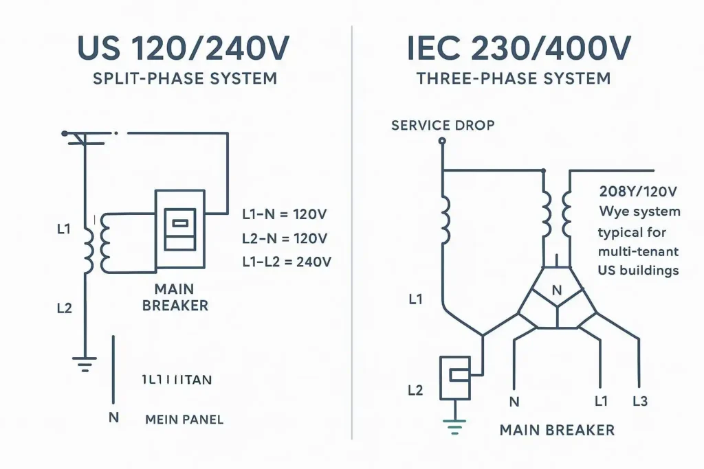
Split-phase service architecture in US homes
Residential service typically arrives from a center-tapped distribution transformer. The center tap is grounded and used as the neutral. Measured to neutral, L1 and L2 each supply ~120V; measured across L1–L2, the service provides ~240V for higher-power loads (dryers, ranges, EVSE). This architecture allows both 120V and 240V branch circuits from the same service without a separate transformer.
ANSI C84.1 voltage ranges and utilization
ANSI C84.1 defines service and utilization ranges at 60 Hz. For 120/240V:
- Range A service operation is typically 114–126 V at 120V (±5%) and 228–252 V at 240V. Range B allows infrequent excursions beyond A. These bounds help explain why a nominal 120V circuit can measure anywhere from ~114 to 126 V in normal conditions. See the ANSI overview and NEMA standard page for definitions and tolerances discussed in 2020/2025 materials: according to the American National Standards Institute’s overview of the standard, acceptable operating ranges are defined for both service and utilization voltages; NEMA’s page details the American National Standard’s scope and adoption. For accessible summaries, see the ANSI article in “ANSI C84.1-2020 electric voltage ratings 60 Hz” and the NEMA page “American National Standard for Electric Power Systems and Equipment—Voltage Ratings.”
- Read more: the high-level summary on acceptable tolerances in the U.S. appears in the American National Standards Institute’s overview of C84.1 and NEMA’s standard landing page, which many utilities follow in their published voltage targets.
References:
- ANSI’s overview of C84.1 ranges is summarized in the institute’s article: see the American National Standards Institute’s discussion of “ANSI C84.1-2020 Electric Voltage Ratings (60 Hz)” which outlines Range A/B behavior and utilization boundaries (ANSI overview).
- NEMA’s landing page for C84.1 provides the current standard context and acquisition path (NEMA C84.1 page).
120V vs 220V in safety and code
Shock physiology and device protection (IEC 60479, GFCI/RCD)
IEC 60479-1 characterizes human response to 50/60 Hz shock using zones (AC-1 to AC-4). The probability of ventricular fibrillation rises as current and time increase; the AC-3/AC-4 boundary informs common 30 mA additional-protection devices that trip quickly to limit exposure. This is the rationale behind RCDs in IEC practice and GFCIs in NEC installations; both aim to interrupt fault current fast enough to keep exposure within survivable zones. See the International Electrotechnical Commission’s publication page for IEC 60479-1 and companion context in IEC 60990 on body impedance and touch current measurement (IEC 60479‑1; IEC 60990).
Terminology: GFCI is the NEC term for personnel-protection ground-fault devices; RCD is the IEC term. Device trip thresholds and application scope vary by region, but the physiological basis is the same.
NEC 2023 branch-circuit scope (GFCI/AFCI, 210/240/250)
At a high level, NEC 2023 addresses:
- 210.5 conductor identification (color marking for ungrounded conductors by system).
- 210.8 GFCI for personnel across dwelling and non-dwelling spaces (subsections (A)–(F)).
- 210.12 AFCI application (e.g., dwelling areas per 210.12(A),(B),(E)).
- 210.19 conductor sizing for branch circuits, including continuous loads at 125% and related notes.
- 210.20 overcurrent protection selection for branch circuits (ties to Article 240 fundamentals).
- 250.122 equipment grounding conductor sizing.
- Article 625 for EVSE circuits (continuous-load treatment and equipment listing/marking).
For clause structure references and public discussion, see NFPA’s NEC Style Manual and NFPA public blog material confirming identifiers and scope (NEC Style Manual 2023). For applied safety work practices and energized-work boundaries, NFPA 70E (2024) Article 130 governs arc-flash risk assessment, labeling, and PPE selection; NFPA’s blogs provide accessible overviews (NFPA 70E energized work permit article; NFPA 70E arc-flash overview).
Code Corner (internal resources): If you need a refresher on miniature and molded-case breakers, selection curves, and coordination concepts, review these primers: miniature circuit breakers for branch circuits and molded-case circuit breakers for feeders and sub-mains:
- See branch-circuit breaker basics in the manufacturer’s overview of miniature circuit breakers (Miniature Circuit Breaker — MCB).
- For feeder/sub-main protection and coordination, see the molded case circuit breaker introduction (Molded Case Circuit Breaker — MCCB).
Earthing/bonding and arc-flash (NFPA 70E) basics
Grounding and bonding decisions affect touch-voltage rise and fault clearing. A correctly sized equipment grounding conductor per NEC 250.122 and a solid main bonding jumper help ensure overcurrent devices operate as intended. Arc-flash risk assessment and labeling are required work practices under NFPA 70E Article 130, which also defines PPE selection methods (PPE categories or incident energy analysis) and approach boundaries. Practically, keeping enclosures in a “normal operating condition,” using listed equipment, and maintaining covers closed reduces risk during operation.
Efficiency and conductor sizing
Current, losses, and voltage drop math
Core relationships:
- Current: I = P / (V × PF × η) for motors; I = P / V for pure resistive loads.
- Conductor loss: P_loss = I² × R (note temperature affects R).
- Approximate single-phase voltage drop (round-trip): ΔV ≈ 2 × I × R_unit × L; ΔV% = (ΔV / V_nom) × 100.
Assumptions used here unless noted: copper conductors, 75°C column behavior approximated using 25°C DC resistances from Southwire and temperature correction if needed; frequency 60 Hz; PF and efficiency stated per case.
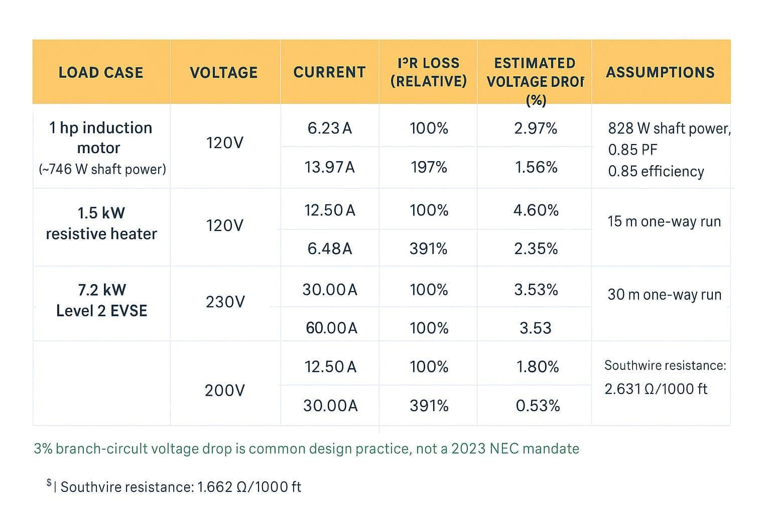
Data reference for resistance: Southwire XHHW‑2 copper (12 AWG: 1.662 Ω/1000 ft; 14 AWG: 2.631 Ω/1000 ft) (Southwire spec). Common design practice targets ≤3% voltage drop on branch circuits and ≤5% feeder+branch; treat these as design guidance rather than a 2023 NEC mandate.
Conductor gauge impacts and panel space
For the same power, 240V halves the current vs 120V. Lower current often means smaller conductors for the same drop target or longer runs at the same gauge, reduced I²R losses and cooler operation, and fewer nuisance trips on motor starts due to less sag. In panels, many 240V loads land on a two-pole breaker, but the overall current headroom improves when fewer high-current 120V circuits are needed.
Motor and heating loads at 120V vs 230–240V
Worked example — 1 hp induction motor on 12 AWG, one-way 30 m (≈98.4 ft), starting current ×6
- Nameplate assumption: 1 hp ≈ 746 W shaft; PF ≈ 0.85; efficiency η ≈ 0.85 (typical small motor). Running input power ≈ 746 / 0.85 ≈ 877 W; apparent power ≈ 877 / 0.85 ≈ 1,032 VA.
- Running current: at 120V, I_run ≈ 1,032 / 120 ≈ 8.6 A; at 230V, I_run ≈ 1,032 / 230 ≈ 4.5 A.
- Locked-rotor current (LRA) estimate ≈ 6 × I_run: ~51.6 A at 120V; ~27.0 A at 230V (actual LRA depends on design letter and starter).
Voltage drop during run (round-trip), using 12 AWG R_25 = 1.662 Ω/1000 ft and L_total ≈ 196.8 ft:
- R_total ≈ 0.327 Ω at 25°C (slightly higher at 75°C).
- ΔV_run: 120V → ~2.8 V (~2.3%); 230V → ~1.5 V (~0.7%).
Starting sag (simplified): 120V → ~16.9 V (~14.1%); 230V → ~8.8 V (~3.8%). These are large enough to influence nuisance tripping and dimming at 120V. Mitigation: upsize conductors, shorten runs, choose higher voltage, or apply soft-start/VFD (see NEC Article 430 for motor protection and controller rules).
Resistive heater intuition — 1.5 kW at 120V vs 230V: I_120 ≈ 12.5 A; I_230 ≈ 6.5 A. Voltage drop and I²R loss fall roughly by a factor of four at higher voltage for the same conductor/run.
EVSE intuition — 7.2 kW Level 2: at 240V draws ~30 A (continuous). At 208V, the same current yields less power; charging rate decreases. Plan panel location/run length to meet drop targets. DOE/AFDC frames Level 2 as 208/240V with typical 30–32 A outputs (AFDC selection guide).
Systems you will encounter
120/240V split-phase vs 208Y/120 in multi-tenant
Many apartments and commercial suites receive 208Y/120V from a three-phase wye. Line-to-neutral remains 120V, but line-to-line is 208V (not 240V). Resistive appliances rated “240V” will run slightly cooler/slower at 208V unless designed for both. Some EVSE and heat pumps specify separate ratings for 208V vs 240V.
230/400V single-phase/three-phase in IEC regions
In IEC regions, single-phase circuits derive 230V from a 230/400V wye system (L-N = 230V, L-L = 400V). Small homes may be single-phase only; larger services may provide three-phase for motors and high-demand appliances. Protective devices commonly use RCDs for additional protection with disconnection time requirements in installation rules.
Appliance ratings, dual-voltage, and certification
Check nameplates and instructions: dual-voltage devices list acceptable ranges and plug/receptacle configurations (NEMA 5-15/20 at 120V; 6-20, 14-30, 14-50, 6-50 for 208–240V). ANSI/NEMA WD 6 defines receptacle geometries and designations in North America (NEMA WD 6). When deploying cross-region, confirm listings and marks (UL/ETL in North America, CE conformity in IEC regions), and ensure the equipment is certified for the target voltage/frequency.
Disclosure: SENTOP is our product. SENTOP supports UL/ETL/CE‑listed OEM/ODM electrical components used in distribution and protection equipment.
PV, storage, and EV loads
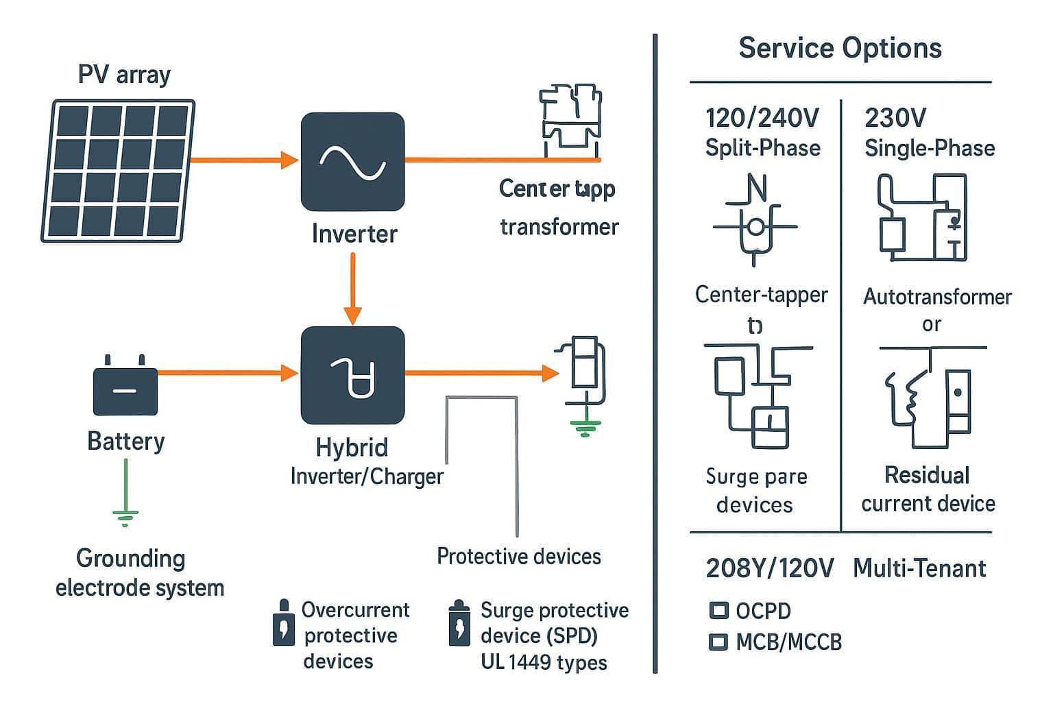
Inverter outputs and transformer steps
Residential hybrid inverters in North America often output 240V split-phase directly and establish a neutral reference via a neutral-forming device in backup modes; many also support 208V operation. In IEC regions, single-phase inverters typically output 230V L-N. Where only a 230V L-L output is available, an autotransformer can derive a center tap to supply 120/240V split-phase loads while managing neutral current and imbalance limits (see manufacturer autotransformer documentation for imbalance ratings, e.g., Victron’s guidance on split-phase derivation and neutral currents) (Victron autotransformer overview). OEM inverter manuals from Enphase and SolarEdge show supported nominal voltages and commissioning considerations for 208V vs 240V operation (Enphase IQ8 datasheet; SolarEdge HD-Wave install guide).
Protection coordination and SPDs across codes
Coordinate overcurrent protection with device and conductor ratings (NEC Articles 210, 240) and size equipment grounding conductors per 250.122. For surge protection, UL 1449 classifies SPDs (Type 1/2/3) and key ratings such as MCOV, VPR, and nominal discharge current In; select and locate SPDs consistent with service topology and equipment SCCR. For a refresher on SPD markings and selection cues, see UL’s application guidance and the lightning protection application guide, which reference UL 1449 within the broader protection system guidance (UL SPD markings overview; UL application guide). For a primer tying SPDs to charger protection concepts in practice, review this explainer on surge protection function indicators in equipment (surge protection function article).
EVSE circuits at 240V and voltage-drop planning
Treat EVSE as continuous loads (NEC 625; size at 125% of nameplate continuous current). A 32 A EVSE typically requires a 40 A two-pole breaker and conductors sized accordingly. On 208Y/120V, the same 32 A setting yields less power than at 240V—plan expectations and run lengths accordingly. Place EVSE near the panel or upsize conductors to keep branch-circuit drop within your design target (often ~3%). DOE/AFDC guides outline typical Level 2 charging ranges and planning considerations for workplaces and residences (AFDC federal workplace charging guide).
Practical verdict: which is better?
Criteria: safety, efficiency, availability
Neither 120V nor 230–240V is inherently “safe.” Shock outcome depends on current and time (IEC 60479‑1). Devices that enforce fast disconnection (GFCI/RCD) and correct bonding/earthing reduce risk. From an efficiency standpoint, higher utilization voltage lowers current and I²R loss, often improving voltage drop and thermal margins over distance—especially for motors and EVSE. Availability varies by region: 120/240V split-phase dominates U.S. residences; 208Y/120V is common in multi-tenant buildings; 230/400V is standard in IEC regions. Design to the service you have.
Use the hybrid advantage in US designs
Use 240V for high-power resistive and motor loads when permitted; it halves current and reduces starting sag. Keep 120V for legacy outlets and low-power loads. For long runs, calculate drop at both 120V and 240V; a modest gauge change or a voltage change can recover margin. Panel space tradeoffs (two-pole vs single-pole) are often offset by lower current.
Cross-region retrofit and procurement tips
Confirm ANSI C84.1 voltage ranges against utility data; choose appliances and EVSE rated for 208V if you’re in multi-tenant U.S. buildings. Check listings and marks: UL/ETL for North America, CE for IEC regions; align plug/receptacle standards (NEMA WD 6). When integrating PV/storage, verify inverter nominal voltage options and whether a neutral-forming device or autotransformer is needed.
Conclusion
Neither voltage is universally superior; context governs. Before selecting a voltage regime, check service architecture (split-phase vs wye), allowable utilization voltage (ANSI C84.1), conductor length and gauge, motor starting behavior, EVSE continuous-load sizing, and protection coordination (NEC 210/240/250; NFPA 70E work practices; UL 1449 for SPDs). Pick the option that delivers safe operation, acceptable voltage drop, and equipment compatibility within your adopted code set.
Quick pre-design checks:
- Identify service type and panel ratings; confirm 120/240V, 208Y/120V, or 230/400V.
- Compute current, I²R loss, and ΔV for the worst run; compare 120V vs 240V.
- Verify listings/marks and nameplate volt/frequency; confirm GFCI/RCD scope.
- Coordinate OCPD, EGC sizing, SPD ratings; label per NFPA 70E.
- For EVSE, treat as continuous load; plan for 208V vs 240V differences.
According to the American National Standards Institute’s overview of C84.1 (2020) and the NEMA C84.1 landing page, acceptable service/utilization ranges frame nominal 120/240V operation in the U.S. For human shock effects and protective device rationale, see the International Electrotechnical Commission’s publication page for IEC 60479‑1. For NFPA 70E work practice requirements and labeling, review NFPA’s Article 130 overviews. External references used once for clarity: ANSI C84.1 overview; NEMA C84.1 page; IEC 60479‑1; NFPA 70E overview blog.
See also
How Many Watts Can a 120V Socket Handle Safely
NEC Code of Junction Box Requirements Made Simple
What Happens When You Plug 120V into a 110V Socket?
Circuit Breaker Selection for Hospital Power Supply Systems
A Practical Guide to Comparing IEC 60898-1 and IEC 60947-2 Standards

Discover more from SENTOP Electrical Co., Ltd
Subscribe to get the latest posts sent to your email.
