
Introduction
You need a clear, code‑aligned answer you can act on. This guide explains placement, exceptions, and how to implement safely. You will get standards context and a practical checklist.
Key takeaways
- In grounded DC systems, place the battery disconnect on the positive conductor (open all ungrounded conductors).
- In floating (ungrounded) DC buses, use a two‑pole DC switch that opens both positive and negative.
- Don’t switch only the negative in grounded systems—it leaves hazardous potentials and often fails inspection.
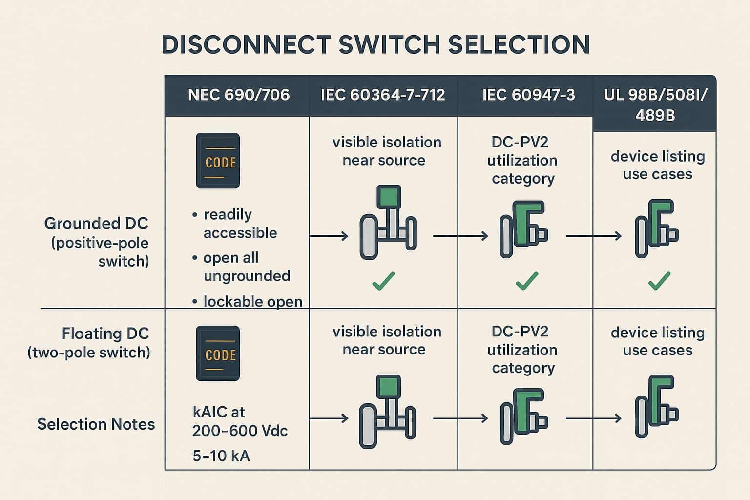
- Size for your envelope: 200–600 Vdc with available fault current of 5–10 kA; verify DC listings and kAIC.
- Ensure accessibility, lockout capability, and durable labels before energizing.
Quick answer: battery disconnect switch placement for PV
Grounded DC default: positive side
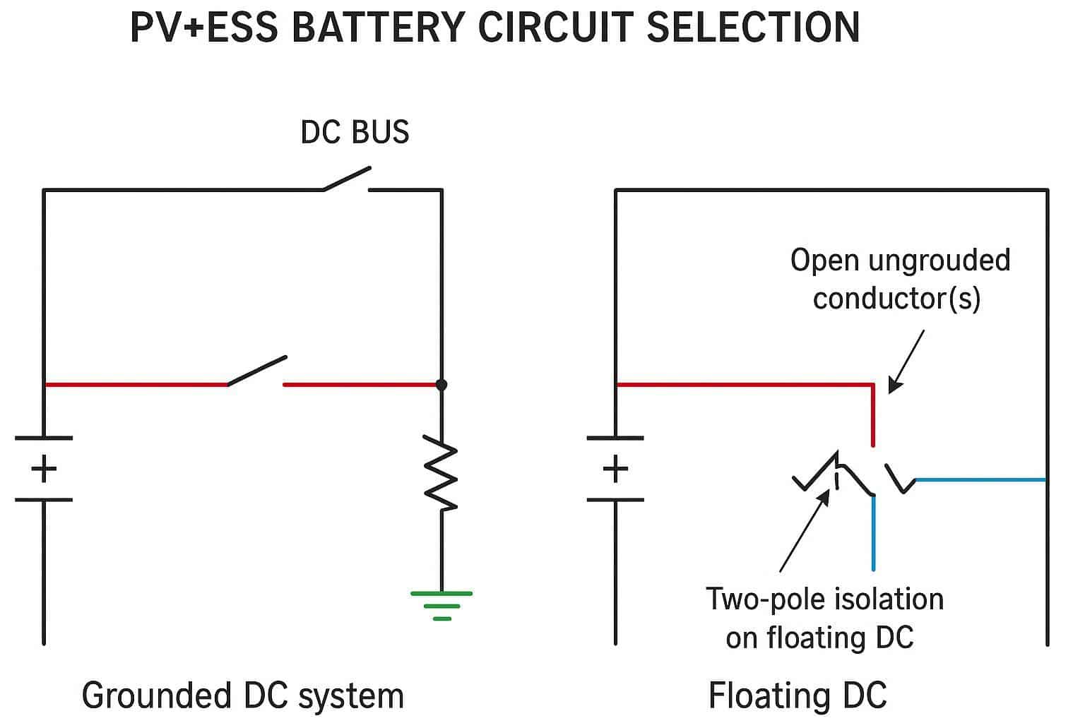
In a typical grounded battery/PV DC bus, one conductor is intentionally bonded to ground (commonly the negative). The other conductor is ungrounded (commonly the positive). The disconnect must open the ungrounded conductor(s). Practically, this means placing the battery disconnect on the positive. This aligns with the NEC interpretation to isolate all ungrounded conductors for PV (Article 690) and ESS (Article 706), as summarized by industry educators such as the explanations in Mike Holt’s 2023 NEC Article 690 overview and ExpertCE’s guide to PV disconnecting means (690.13/690.15).
Floating DC buses: two-pole open
For ungrounded (floating) DC systems, both current‑carrying conductors are ungrounded. To fully isolate the battery from the rest of the system, use a two‑pole DC disconnect that opens both positive and negative simultaneously. This prevents backfeed paths and ensures safe maintenance conditions at the device and the work zone.
Avoid switching only negative
Switching only the negative in a grounded system defeats the isolation intent. The positive remains energized with respect to ground, creating shock and arc hazards and confusing field testing. Many AHJs will flag this during inspection because the ungrounded conductor has not been opened.
Codes and standards
NEC 690/706 essentials
Under the NEC, the PV system disconnecting means must be readily accessible and must simultaneously disconnect all ungrounded PV conductors from other wiring systems. Educational summaries of 2023 NEC Article 690 and 690.13/690.15 emphasize location, accessibility, and marking, including the requirement to open all ungrounded conductors and to apply permanent identification such as “PV SYSTEM DISCONNECT.” See the interpretations in Mike Holt’s Solar Part 3 (2023 NEC Article 690) and the ExpertCE PV disconnecting means overview for clarity on “readily accessible” and marking guidance.
Authoritative code excerpts (NEC 2023 / UL) — selected clauses
- NEC 690.13 — “Disconnecting means shall simultaneously disconnect all ungrounded PV conductors.” (NEC 2023, NFPA 70, Art. 690.13)
- NEC 706.15 — “Means shall be provided to disconnect the ESS from all wiring systems; location options and lockable‑open provisions apply.” (NEC 2023, Art. 706.15)
- NEC 110.25 — Locking provisions for disconnecting means (see NFPA 70, Art. 110.25).
Refer to NFPA 70 (NEC 2023) for full authoritative text; consult device nameplate/listing for UL standard applicability (UL 98B / UL 508I / UL 489B).
For energy storage systems, Article 706 requires a disconnecting means to isolate the ESS from all wiring systems, with options for location: within the ESS, within sight and within 10 ft (3 m), or not within sight but capable of being locked in the open position (110.25). Mayfield Renewables’ 2023 NEC update for ESS and additional explainers from ECM and HeatSpring provide practical interpretations of these requirements and when a maintenance disconnect within sight is expected for field‑serviceable batteries.
IEC 60364 and 60947-3
IEC practice points in the same direction: provide a DC isolator near the source and ensure visible isolation. Device performance is tied to IEC 60947‑3 utilization categories; for PV/ESS, DC‑PV2 is preferred because it’s tested for PV duty (including backfeed and high L/R time constants). Manufacturer catalogs summarizing DC‑PV categories—such as Socomec’s INOSYS DC catalog extract (IEC 60947‑3; DC‑PV)—are useful references when selecting devices in IEC markets.
UL 98B/508I/489B use cases
- UL 98B: Enclosed or dead‑front PV DC switches used for isolation on PV/ESS DC circuits. Choose when isolation is the primary function and fault interruption is provided elsewhere. See an application summary in Eaton’s UL 98B DC disconnects brochure.
- UL 508I: Manual PV disconnects used within equipment—confirm ratings and application notes for your exact duty (manufacturer and UL Product iQ details apply).
- UL 489B: Molded‑case devices for PV systems used when you need both isolation and DC fault interruption; verify the Vdc and kAIC at 200–600 Vdc within your 5–10 kA envelope. See NFPA/UL references and manufacturer catalogs for device‑specific ratings.
Implementation checklist
Ratings and interrupt capacity
- Voltage: Size to the maximum DC open‑circuit voltage (Voc) of the battery/PV segment, with margin appropriate to your spec. In 200–600 Vdc C&I systems, both 600 and 1000 Vdc devices are common; verify per‑pole Vdc and any permitted series‑pole configurations in the datasheet. For IEC‑style devices and DC‑PV categories, see Socomec’s INOSYS DC extract (IEC 60947‑3; DC‑PV).
- Available fault current: Confirm the device’s DC interrupting or short‑circuit withstand rating for 5–10 kA at your system voltage. If the switch relies on upstream fuses/breakers, validate the series rating and protective device class per the manufacturer’s tables. A concise overview of UL 98B PV DC switches is in Eaton’s brochure.
- DC listing: Use devices listed for the duty—UL 98B or UL 508I for manual DC switches; UL 489B where DC fault interruption is required; or IEC 60947‑3 DC‑PV2 where permitted by jurisdiction.
- Thermal/environmental derating: Check ambient temperature curves and enclosure heat rise to avoid nuisance issues. High currents in compact enclosures can drive temperatures beyond rating.
- Further reading on coordination: For foundational context on trip curves and thermal‑magnetic behavior, see the SENTOP blog’s guide to MCB trip curves: trip curves and thermal‑magnetic behavior.
Mini worked example (kAIC check):
- Project: battery/PV segment Voc = 450 Vdc; available short‑circuit current ≈ 5–10 kA; upstream protection = UL 489B MCCB rated 10 kAIC.
- Check: select a disconnect/breaker with Ue ≥ 600 Vdc (margin above Voc) and interrupting rating ≥ 10 kA at the operating Vdc. If using a UL 98B switch, verify it is series‑rated with the upstream UL 489B device per the manufacturer’s coordination notes (see Eaton UL 98B brochure and ABB SACE Emax DC guidance).
Location and lockout
- Accessibility: For PV, the system disconnecting means must be readily accessible and operable without exposure to energized parts. Identify the device clearly as a “PV SYSTEM DISCONNECT” when it serves that function. See interpretations in Mike Holt’s overview and ExpertCE’s guide.
- ESS placement options: For ESS, you may place the disconnect within the ESS, within sight and within 10 ft (3 m), or not within sight if it can be locked open per 110.25. Practical context is covered in Mayfield Renewables’ update and explainers from ECM and HeatSpring.
- Working space and environment: Maintain required clearances and select enclosures suitable for the location—NEMA 3R minimum outdoors; NEMA 4/4X or IP65+ for harsh or rooftop exposure.
- Handle and hasp: Provide a lockable handle or external hasp for lockout/tagout. If the disconnect isn’t within sight of the ESS, ensure the locking provision is present and documented.
Labels, diagrams, tests
- Labels and markings:
- Apply durable labels: “PV SYSTEM DISCONNECT” for PV circuits and “ENERGY STORAGE SYSTEM DISCONNECT” where applicable.
- Mark polarity and line/load clearly on the device and in the panel.
- Diagrams:
- Update the single‑line diagram (SLD) to explicitly show whether the DC bus is grounded or floating and which poles are opened by each disconnect (PV vs ESS). For floating buses, annotate the two‑pole isolation on the battery side.
- Commissioning tests (no‑load where required by device markings):
- Visual inspection: Listing standard visible; enclosure rating; lockable feature; polarity markers.
- Polarity verification: Meter check for +/– per SLD; continuity check with switch open/closed.
- Insulation resistance: Conductor‑to‑ground and conductor‑to‑conductor values per project spec (e.g., >1 GΩ for new work, if specified).
- Functional open test: With no load, operate the disconnect and verify de‑energization downstream.
- Documentation alignment (what to file for AHJ and O&M):
- Device datasheet excerpt showing the DC listing (UL 98B/UL 508I/UL 489B or IEC 60947‑3 DC‑PV2), rated Vdc, current, and kAIC/withstand.
- Photos of the installed device showing labels, polarity, and lockout provision.
- Updated SLD highlighting opened poles and grounding scheme; commissioning checklist signed.
- Supplier material: As an example of what to archive from a vendor, suppliers like SENTOP typically provide datasheets and compliance statements that you can file alongside your SLDs for review. Disclosure: SENTOP is our product. Ensure the vendor claims match the device nameplate and the applicable standard in your jurisdiction.
- Optional internal reading on label literacy: See this primer on certifications and label reading: identify certified MCCB labels.
Conclusion
Put the battery disconnect switch on the positive in grounded systems. Use a two‑pole DC switch to open both conductors in floating systems. Before energizing, verify DC ratings, accessibility, lockout, and clear labeling—then capture your evidence in the documentation pack. This approach to battery disconnect switch placement for PV is straightforward, code‑aligned, and inspection‑ready.
See also
What Homeowners Should Know Before Replacing a Fuse Disconnect
Inverter SPD vs Standard Surge Protector: What’s the Difference?
What Determines How Many Solar Combiner Boxes You Need
Installation position and precautions of solar combiner box
Grid connected photovoltaic power ATS

Discover more from SENTOP Electrical Co., Ltd
Subscribe to get the latest posts sent to your email.
