
Electrical faults cause an estimated 24,000 industrial fires each year in the United States alone, and the overcurrent protection device you choose directly determines how much damage a fault inflicts before it’s interrupted. So, circuit breaker vs fuse — which is better for industrial use? The honest answer: neither device “wins” universally. Circuit breakers offer resettability and remote monitoring that reduce downtime in complex facilities, while fuses deliver faster current-limiting performance and higher interrupting ratings per dollar in high-fault environments. The right pick depends on your specific fault levels, maintenance capacity, coordination requirements, and total cost of ownership — all of which this guide breaks down in detail.
Circuit Breaker vs Fuse — The Short Answer for Industrial Applications
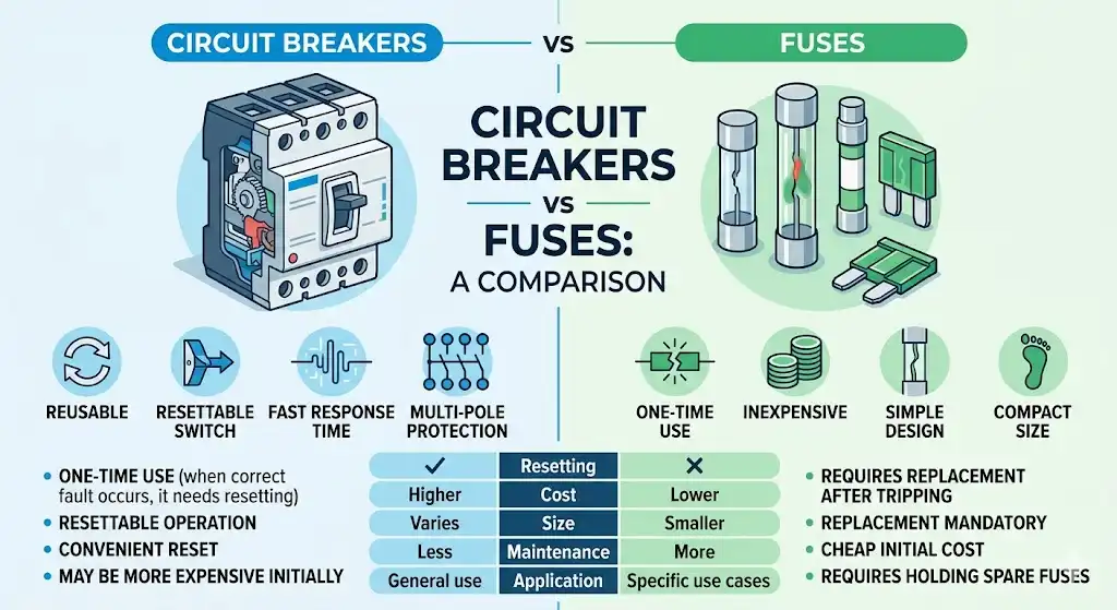
Neither one universally wins. That’s the honest answer. When asking which is better for industrial use — circuit breaker vs fuse — the real question is what specific protection job needs doing. Each device dominates in different scenarios, and experienced engineers spec both within the same facility.
Fuses excel where extreme fault currents demand near-instantaneous interruption. Their current-limiting ability can cap a 200 kA prospective fault down to a fraction of that energy in under half a cycle — roughly 4 milliseconds on a 60 Hz system. That kind of speed protects expensive downstream equipment like variable frequency drives and semiconductor stacks from catastrophic damage. No moving parts means no mechanical wear, and fuse interrupting ratings often reach 300 kA without breaking a sweat.
Circuit breakers win on convenience and operational flexibility. They reset after a trip, which slashes downtime in production environments where every idle minute costs real money. Modern electronic trip units offer adjustable settings for long-delay, short-delay, instantaneous, and ground-fault thresholds — all tunable without swapping hardware. For motor circuits requiring frequent overload protection adjustments, that flexibility matters enormously.
The practical reality? Most industrial distribution systems use both. Main switchgear might rely on breakers for their monitoring and remote-operation capabilities, while branch circuits feeding high-fault-current zones use current-limiting fuses. The NEC (NFPA 70) doesn’t favor one over the other — it sets performance requirements and lets engineers choose. The sections ahead break down exactly where each device earns its place.
How Circuit Breakers and Fuses Work Differently at a Fundamental Level
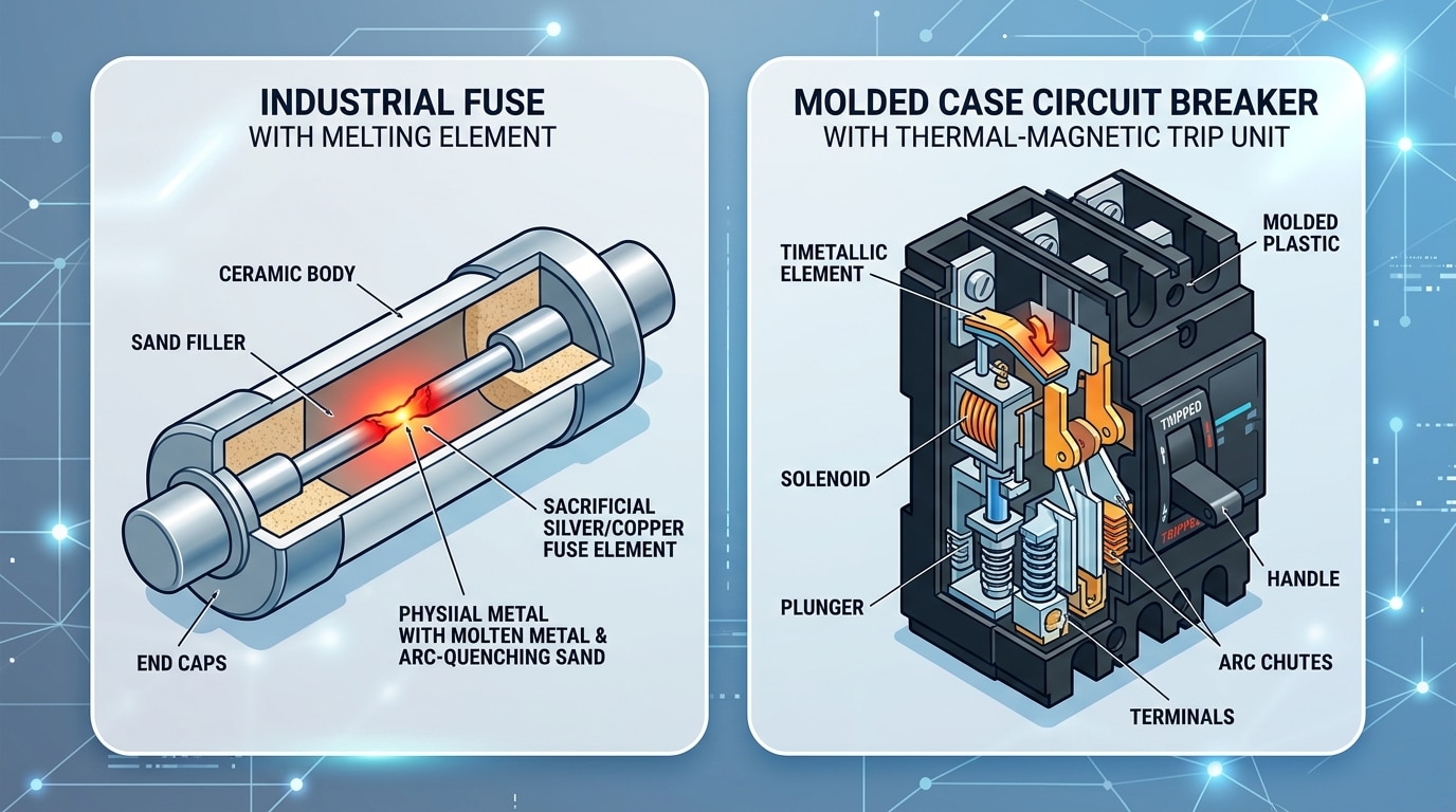
A fuse is, at its core, a deliberate weak point. Inside the fuse body sits a precisely calibrated metal element — typically zinc, copper, or silver — engineered to melt when current exceeds a specific threshold. The element heats up, liquefies, and creates an arc gap that extinguishes the circuit. Once that happens, the fuse is dead. You replace it. There’s no reset button, no second chance.
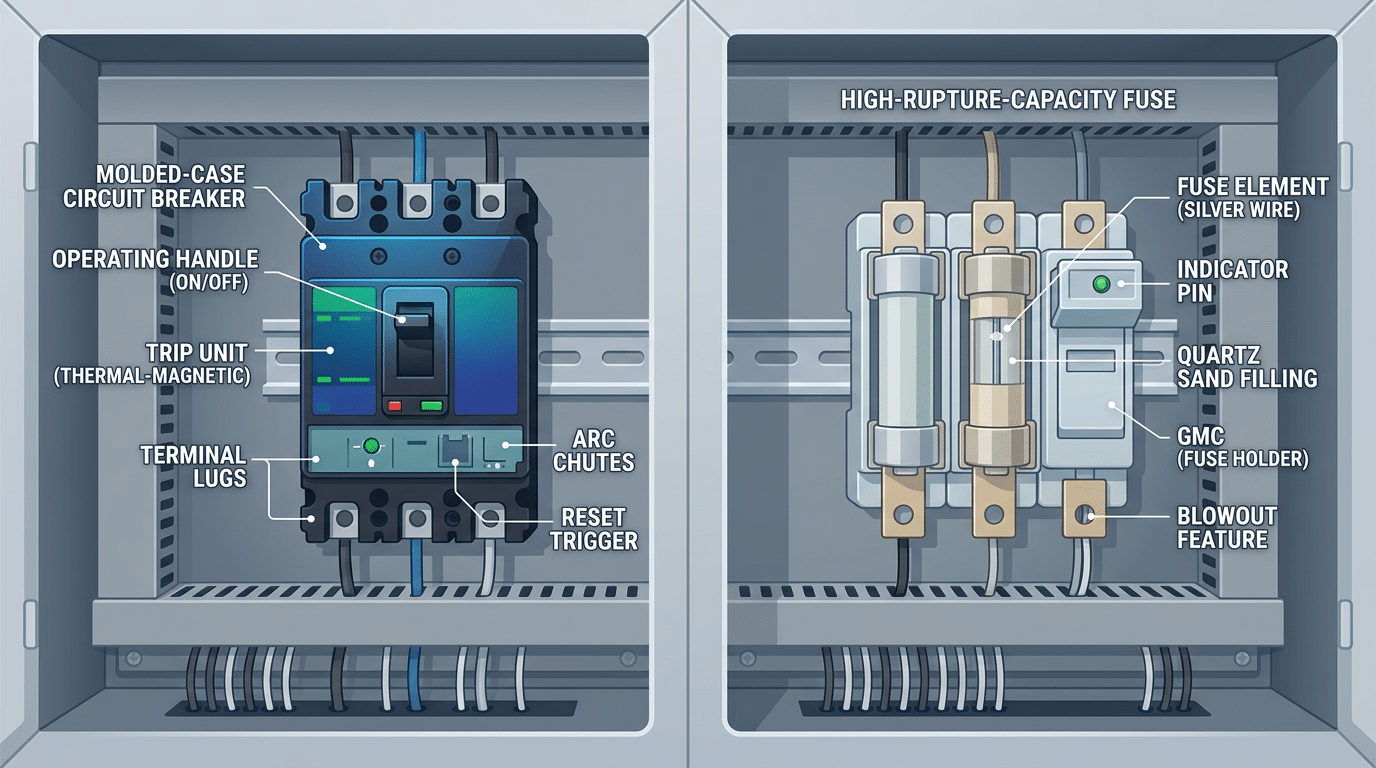
Circuit breakers take a completely different approach. They use mechanical contacts held closed by a latch mechanism, which gets released by a trip unit when fault current flows. That trip unit might be a bimetallic strip that bends under heat (thermal), an electromagnet that pulls a lever under high current (magnetic), or a microprocessor analyzing the waveform in real time (electronic). The contacts separate, an arc chute quenches the resulting arc, and the breaker can be reset — manually or remotely — within seconds.
This fundamental distinction — sacrificial element versus reusable mechanism — drives almost every practical difference you’ll encounter when evaluating circuit breaker vs fuse which is better for industrial use. Fuses respond passively to physics; they have no moving parts, no calibration drift, no mechanical wear. Circuit breakers respond actively, which gives operators flexibility but introduces components that can degrade over thousands of operations. The National Electrical Manufacturers Association (NEMA) publishes separate performance standards for each device precisely because their failure modes and protection characteristics are so fundamentally different.
Fuse Operating Principle and Current-Limiting Behavior
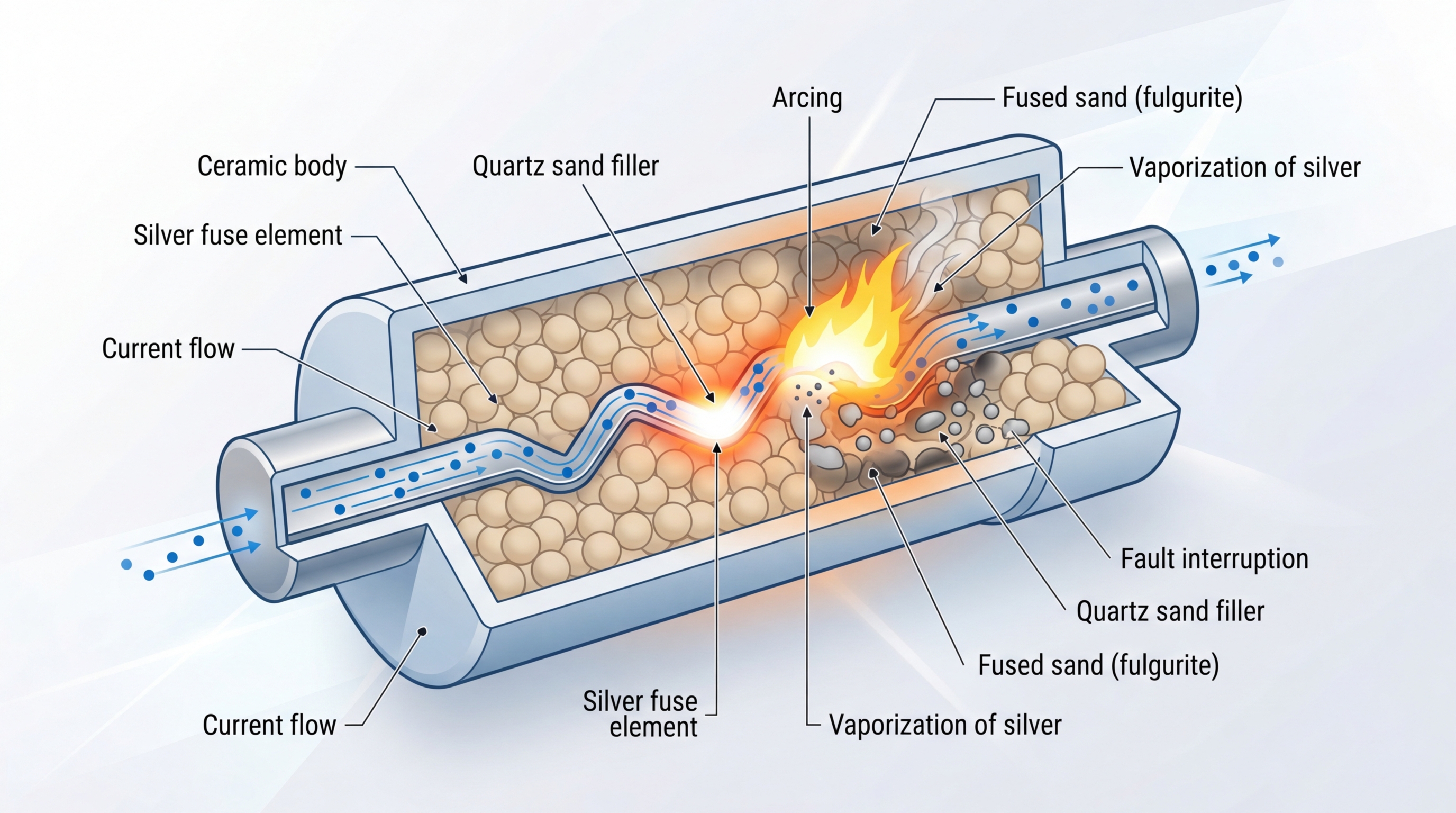
Industrial fuses don’t just interrupt faults — they strangle them before the current reaches its prospective peak. An HRC (High Rupture Capacity) fuse contains a precisely calibrated silver or copper element surrounded by quartz sand filler. When fault current flows, the element melts at engineered weak points called notches, and the resulting arc vaporizes into the sand. This arc energy gets absorbed in microseconds, typically clearing the fault within half a cycle — roughly 4 to 5 milliseconds on a 50 Hz system.
This is current limiting in action. The fuse forces the actual let-through current (called I²t) far below what the prospective fault current would have been. On a bus with 100 kA available fault current, a properly rated HRC fuse might limit peak let-through to under 15 kA. That difference matters enormously for downstream equipment stress. According to Eaton’s fuse engineering resources, this current-limiting behavior directly reduces the mechanical and thermal forces on conductors, busbars, and switchgear.
Different fuse types serve different industrial loads. Semiconductor fuses operate even faster — clearing in under 3 ms — to protect sensitive thyristors and IGBTs in variable frequency drives. Dual-element fuses combine a short-circuit element with a time-delay overload element, making them ideal for motor circuits that draw 6× to 8× inrush current on startup. When evaluating circuit breaker vs fuse which is better for industrial use, this inherent current-limiting physics gives fuses a hard-to-match edge in high-fault-current environments where equipment protection is the top priority.
Circuit Breaker Trip Mechanisms — Thermal, Magnetic, and Electronic
Not all circuit breakers trip the same way. The trip mechanism defines how quickly and precisely a breaker responds to different fault types — and in industrial environments, that distinction matters enormously. Three core technologies dominate: thermal, magnetic, and electronic.
Thermal trip units use a bimetallic strip that bends as current heats it. The higher the overload, the faster the strip deflects and triggers the latch. Response is inherently time-delayed, which is useful for tolerating motor inrush currents that spike to 6–8× full load amperage for a few seconds. But thermal elements drift with ambient temperature. A breaker in a 50°C panel enclosure trips sooner than the same unit at 25°C.
Magnetic trip units handle the opposite end of the spectrum. A solenoid or electromagnet activates instantaneously when current hits a fixed threshold — typically 5–10× the breaker’s rated current. This is the short-circuit response. Fast, binary, no time delay. Most molded-case circuit breakers (MCCBs) combine both thermal and magnetic elements into a single “thermal-magnetic” trip unit, covering overloads and short circuits in one device.
Electronic trip units change the game entirely. Found in higher-end MCCBs, insulated-case breakers (ICCBs), and air circuit breakers (ACBs), these microprocessor-based systems allow adjustable pickup settings, time-delay curves, and ground fault protection — all programmable. According to Eaton’s technical documentation, electronic trip units offer long-time, short-time, instantaneous, and ground fault (LSIG) protection in a single package. That level of selectivity is a major reason why, when evaluating circuit breaker vs fuse which is better for industrial use, breakers often win on coordination flexibility.
Each mechanism has tradeoffs. Thermal-magnetic units are affordable and reliable but offer zero adjustability. Electronic units cost 3–5× more upfront but let engineers fine-tune protection curves to match specific loads without swapping hardware.

Key Differences in Industrial Fault Protection Performance
The debate around circuit breaker vs fuse which is better for industrial use often comes down to one critical metric: let-through energy, expressed as I²t. This value represents the total thermal energy a protective device allows to pass before it clears the fault. Lower I²t means less stress on downstream equipment — and that matters enormously when you’re protecting a $15,000 variable frequency drive or a custom-wound transformer with a 20-week lead time.
Current-limiting fuses excel here. A Class J fuse can limit peak let-through current to a fraction of the available fault current, often clamping a 100 kA prospective fault down to under 15 kA within the first half-cycle. Molded-case circuit breakers, by contrast, typically need 3–5 cycles to fully interrupt, allowing significantly more energy through. That gap in speed translates directly into equipment damage — or the lack of it.
Selectivity, or coordination, is where breakers fight back. Electronic trip units in modern industrial breakers allow precise zone-selective interlocking, meaning only the device nearest the fault opens. Achieving the same coordination with fuses requires careful ratio analysis — generally a 2:1 ampere rating ratio between upstream and downstream fuses, per Eaton’s coordination guidelines. Get that ratio wrong, and both fuses blow.
Interrupting ratings also diverge sharply. High-performance fuses routinely carry 200 kA or 300 kA interrupting ratings in compact packages. A comparable breaker rated above 65 kA often requires a larger frame size or an expensive high-interrupting-capacity model. For facilities with stiff utility feeds and fault currents exceeding 100 kA, fuses provide a more straightforward — and often more economical — path to adequate protection.
Total Cost of Ownership — Fuses vs Circuit Breakers Over 10 Years
Upfront price tags lie. A Class J fuse might cost $15–$40 per pole, while a comparable molded-case circuit breaker runs $150–$600. That gap looks enormous on a purchase order — but it collapses fast once you factor in what happens after installation.
Fuses need replacement after every fault event. In a facility experiencing 3–5 significant faults per year on a given feeder, replacement fuse costs, electrician callouts, and production downtime stack up quickly. Each replacement also demands correct spare inventory — stocking the wrong amperage or class is a real risk that has caused secondary failures in the field. The NFPA emphasizes proper maintenance protocols precisely because mismatched replacements create hazards.
Circuit breakers reset. No spare parts needed, no inventory headaches. But they do require periodic testing — contact resistance checks, trip-unit calibration, lubrication of operating mechanisms — typically every 3–5 years. Skip that maintenance, and a breaker can fail to trip when it matters most. Those service contracts aren’t cheap, often $200–$500 per breaker for a comprehensive test cycle.
Panel space matters too. Fuse holders generally occupy less DIN rail or panel real estate than equivalent breakers, which can reduce enclosure size and installation labor by 10–20%. When evaluating circuit breaker vs fuse which is better for industrial use from a pure TCO perspective, the answer depends heavily on fault frequency. Low-fault environments tend to favor breakers over a decade. High-fault feeders — especially those protecting motors with frequent locked-rotor events — can make fuses more economical despite repeated replacements, because the alternative is expensive breaker servicing after repeated high-stress trips.
When Fuses Are the Better Choice in Industrial Settings
Fuses dominate when fault currents get extreme. In heavy industrial facilities — steel mills, large chemical plants, utility substations — available fault currents can exceed 100kA or even reach 200kA. Most molded-case circuit breakers top out at 65kA interrupting capacity, and even high-end power breakers rarely exceed 100kA without series-rated combinations. A Class L fuse handles 200kA without flinching, and it costs a fraction of a breaker with comparable ratings.
Semiconductor protection is another clear win. Variable frequency drives, SCR stacks, and IGBT modules can be destroyed in under 4 milliseconds by an overcurrent event. Standard circuit breakers simply cannot clear fast enough. Semiconductor fuses (Class aR per IEC or UL Class T in some applications) operate within sub-cycle timeframes — often under 8ms total clearing time at high fault levels — providing the precise I²t limitation these sensitive components demand. No breaker matches that speed.
Budget matters too. When evaluating circuit breaker vs fuse which is better for industrial use, cost-per-ampere of interrupting capacity tilts heavily toward fuses in high-fault environments. A 200kA-rated fuse assembly might run $200–$500 per pole. Achieving equivalent protection with breakers could cost 5–10x more, especially once you factor in the required enclosure upgrades. For facilities that need high interrupting ratings across dozens of branch circuits, fuses keep the electrical infrastructure budget realistic without compromising safety. The NEMA Low Voltage Fuse standards outline the performance benchmarks that make this possible.
When Circuit Breakers Outperform Fuses in Industrial Plants
Downtime kills profitability. In facilities running continuous processes — food packaging lines, pharmaceutical batch operations, semiconductor fabs — a blown fuse means someone has to physically locate the correct replacement, verify its rating, and install it. That sequence can take 20–45 minutes depending on spare parts availability and panel accessibility. A circuit breaker? Reset it in under 30 seconds.
Automation integration is where circuit breakers pull far ahead. Modern electronic-trip breakers communicate over Modbus, Profibus, or Ethernet/IP, feeding real-time current data into SCADA and BMS platforms. Plant engineers can monitor load trends, receive pre-trip warnings, and even actuate shunt-trip coils remotely. Fuses offer none of this visibility. For facilities investing in Industry 4.0 infrastructure, that gap matters enormously when evaluating circuit breaker vs fuse which is better for industrial use.
Adjustable trip settings solve another persistent headache. Consider a plant with variable-speed drives that produce high inrush currents during ramp-up. Fixed fuse characteristics may cause nuisance blows at startup, forcing operators to oversize fuses — which weakens downstream protection. Electronic-trip circuit breakers from manufacturers like Eaton let you dial in long-time delay, short-time pickup, and instantaneous thresholds independently. That tunability eliminates nuisance trips without sacrificing fault protection.
Plants with frequent load changes or expansion plans also benefit. Adding a new production cell doesn’t require swapping fuse holders for higher ratings — you adjust the breaker’s settings or swap the trip unit alone. Flexibility like this reduces both engineering time and panel modifications during facility upgrades.
NEC and IEC Code Considerations for Industrial Overcurrent Protection
Electrical codes don’t just suggest — they dictate. In many industrial scenarios, the question of circuit breaker vs fuse which is better for industrial use gets answered by the codebook before an engineer even opens a catalog.
NEC Article 240 governs overcurrent protection broadly, but the real teeth show up in Article 430 for motor circuits. Section 430.52 caps the maximum size of short-circuit protective devices based on motor type — and the permitted percentages differ between fuses and inverse-time breakers. A dual-element time-delay fuse can typically be sized at 175% of full-load current, while an inverse-time breaker gets 250%. That sizing gap matters. It affects coordination, wire sizing, and fault withstand ratings downstream.
Transformer protection under NEC 450.3 adds another wrinkle. Primary-only protection on transformers over 1000V allows fuses at 300% of rated current in certain configurations — but circuit breakers get tighter limits at 300% only when secondary protection is also provided. Miss that detail, and you fail inspection.
IEC Standards and Arc Flash Implications
On the IEC side, 60947-2 covers circuit breakers while 60269 addresses fuses. IEC frameworks tend to emphasize short-circuit coordination studies more explicitly, and current-limiting fuses often simplify compliance with IEC 61439 assembly standards by reducing prospective let-through energy. For arc flash mitigation — increasingly critical under NFPA 70E — current-limiting fuses can drop incident energy below 1.2 cal/cm², sometimes eliminating the need for arc-rated PPE at certain panels. Circuit breakers achieve similar results only with zone-selective interlocking or arc flash relay add-ons, which increase cost and complexity.
Real-World Scenarios — Motor Circuits, Lighting Panels, and High-Fault Environments
Large Motor Control Centers
Motors draw 6–8× their full-load current on startup. That inrush wreaks havoc on standard overcurrent devices. For motors above 50 HP, dual-element time-delay fuses (Class RK1 or J) handle the inrush without nuisance tripping while still providing current-limiting protection during a locked-rotor fault. Circuit breakers with adjustable electronic trip units work here too — but they cost roughly 3× more per starter bucket and don’t limit let-through energy the way fuses do.
Industrial Lighting and Distribution Panels
Lighting panels trip often. Ballast failures, LED driver shorts, loose connections in branch circuits — these faults are frequent and minor. Molded-case circuit breakers win decisively here. A maintenance electrician resets the breaker in seconds. No spare fuse inventory, no sizing confusion, no downtime waiting for replacements. For anyone weighing circuit breaker vs fuse which is better for industrial use on distribution panels below 100A per branch, breakers are the practical choice.
Facilities With Available Fault Current Above 65 kA
This is where the conversation shifts hard. Many molded-case breakers top out at 65 kA interrupting capacity. Fuses? Class J and Class L fuses handle 200 kA and 300 kA respectively. Facilities fed by large utility transformers — data centers, petrochemical plants, steel processing — routinely see available fault currents of 85–150 kA at the main bus. According to Eaton’s fuse selection guide, current-limiting fuses remain the most cost-effective way to protect equipment at these levels without upgrading the entire switchgear lineup.
Maintenance and Downtime Comparison for Industrial Facilities
After a fault trips a circuit breaker, a qualified technician can reset it in under 2 minutes. Restoring power through a blown fuse takes longer — typically 10–30 minutes — because the technician must identify the faulted fuse, verify the correct replacement rating, and physically swap the element. That gap matters enormously in continuous-process plants where every minute of downtime can cost $5,000 or more in lost production.
Skill requirements differ sharply. Resetting a molded-case breaker requires basic lockout/tagout knowledge. Fuse replacement, however, demands that maintenance staff correctly match voltage rating, ampere rating, interrupting capacity, and class designation — a mismatch creates a serious safety hazard. Stocking the wrong spare is a surprisingly common failure mode in facilities with dozens of fuse sizes across multiple panels.
Arc flash exposure is where the comparison gets critical. Current-limiting fuses reduce incident energy dramatically — often below 1.2 cal/cm², which allows technicians to work in minimal PPE. Circuit breakers, especially older models without zone-selective interlocking, can produce incident energy levels exceeding 40 cal/cm² at the panel, requiring full arc flash suits rated to HRC 4. NFPA 70E mandates that employers calculate these values for every maintenance task, and the protective device directly shapes those numbers.
Testing procedures also diverge. Breakers need periodic trip testing — every 3–5 years per manufacturer recommendations — using primary or secondary injection equipment. Fuses require no functional testing; they either work or they’ve already operated. When evaluating circuit breaker vs fuse which is better for industrial use from a pure maintenance burden perspective, fuses demand less ongoing verification but more logistical discipline around spare parts inventory.
Frequently Asked Questions About Fuses and Circuit Breakers in Industrial Use
Can you mix fuses and breakers in the same industrial system?
Yes — and many facilities do exactly that. A common design pairs current-limiting fuses on the main incoming service (where available fault current is highest) with circuit breakers on downstream branch circuits for easier reset. The key requirement: selective coordination. Per NFPA 70 (NEC) Article 240, the upstream device must clear before the downstream one to avoid cascading outages.
Which device provides better arc flash protection?
Current-limiting fuses reduce incident energy dramatically — often by 80% or more — because they cut fault current within the first half-cycle. Circuit breakers with instantaneous trip settings help too, but they typically clear in 3–5 cycles. For arc flash mitigation specifically, fuses hold a measurable edge.
Have smart circuit breakers eliminated the fuse advantage?
Not entirely. Smart breakers offer remote monitoring, predictive analytics, and programmable trip curves — huge wins for operational flexibility. But physics still matters. No electronic trip unit changes the mechanical clearing speed of a breaker. When the question is circuit breaker vs fuse which is better for industrial use in ultra-high fault current environments (100 kA+), fuses remain faster at interruption.
How should I choose for a new facility design?
Start with a fault current study. If prospective fault levels exceed 65 kA, lean toward fuses at the service entrance. If your process demands rapid restart after nuisance trips, prioritize breakers on branch circuits. Most industrial designs benefit from a hybrid approach tailored to each load’s risk profile.
Final Verdict — Making the Right Choice for Your Industrial Application
There’s no single winner. The question of circuit breaker vs fuse which is better for industrial use always circles back to your specific facility, your specific fault conditions, and your tolerance for downtime versus upfront cost.
Use this decision checklist before specifying overcurrent protection on your next project:
- Available fault current exceeds 100 kA? Lean toward current-limiting fuses — they’ll cap let-through energy far faster than most breakers can react.
- Process can’t tolerate even 15 minutes of downtime? Circuit breakers with remote reset capability pay for themselves quickly.
- Budget is tight and the load is straightforward? Fuses cost 40–70% less per pole upfront and require zero calibration.
- You need granular trip curves or zone-selective interlocking? Electronic-trip breakers give you programmable flexibility fuses simply can’t match.
- Motor inrush is a recurring nuisance-trip problem? Dual-element time-delay fuses handle it cleanly.
Many well-designed industrial systems use both — fuses on high-fault branch circuits, breakers on feeders where coordination and monitoring matter most. That hybrid approach often delivers the best balance of safety, cost, and uptime.
One non-negotiable recommendation: for any installation above 600 V or with available fault currents exceeding 65 kA, engage a licensed professional engineer to run a formal coordination and arc-flash study per NFPA 70E. The math matters too much to guess.
See also
What is the difference between a circuit breaker and a fuse?
What Does the KA Rating Mean on Circuit Breakers
The difference between miniature circuit breakers and fuses
Can I replace a fuse with a circuit breaker?
What Makes Distribution Boxes and Fuse Boxes Different

