
Load and inrush
Normal current, duty, electronic input, motor start, transformer energization, and simultaneous switching.

There is no single best MCB for every building circuit. Type B is a common candidate for verified low-inrush loads. Type C may suit higher inrush. Type D is a specialist choice. The final device must also match the conductor, fault level, poles, voltage, distribution board, and locally required RCD, RCBO, AFDD, or surge protection.
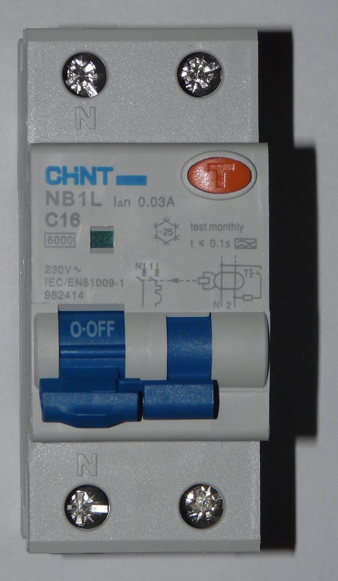
Photo: Shixart1985 / Wikimedia Commons, CC BY 2.0; cropped and darkened for display. The image does not establish any breaker's rating or compliance.
A candidate MCB is not approved until all five boundaries below are known. If fault or conductor data are missing, the safe status is confirm before selection.
Normal current, duty, electronic input, motor start, transformer energization, and simultaneous switching.
Cable material, cross-section, installation method, grouping, ambient temperature, and termination limits.
Prospective short-circuit current, earth-fault loop conditions, and the required automatic disconnection time.
Standard, rated current, poles, AC/DC voltage, breaking capacity, busbar, terminals, and accessories.
RCCB/RCD or RCBO, AFDD/AFCI, SPD, upstream coordination, local rules, test records, and project documents.
For many IEC-style building final circuits, the first comparison is Type B versus Type C. Type B has a lower instantaneous magnetic threshold and often fits low-inrush loads. Type C allows more short inrush, but the circuit must still produce enough fault current for the required disconnection. Type D should be limited to a dedicated, verified high-inrush application.
A characteristic with a higher instantaneous threshold is not automatically “stronger.” It can reduce nuisance trips, but it can also require a higher fault current for rapid operation. That is why cable length, loop impedance, earthing arrangement, and the exact time-current curve matter.
Choose the curve that sits between two boundaries: above the legitimate inrush that should not trip, and below the minimum fault current that must trip within the required time. Then verify every other rating.
The thermal element handles sustained overload. The magnetic element responds quickly to high overcurrent. The letter mainly identifies the high-current magnetic region.
| Curve | Illustrative magnetic range | Building-circuit candidate | Evidence required | Do not assume |
|---|---|---|---|---|
| Type B | 3–5 × In is the commonly stated IEC 60898-1 instantaneous band. | Low-inrush resistive loads and some final circuits. | Actual electronic/appliance inrush, conductor capacity, and fault-clearing result. | That every lighting or residential circuit is automatically Type B. |
| Type C | 5–10 × In is the commonly stated IEC 60898-1 instantaneous band. | Circuits with moderate inductive or electronic inrush. | Starting current and duration, remote-end fault current, and exact TCC. | That “commercial building” alone proves Type C. |
| Type D | 10–20 × In is the commonly stated IEC 60898-1 band; a named product may declare a narrower actual band. | Selected motors, transformers, or specialist equipment with verified high inrush. | Full starting profile, fault-loop/disconnection check, and protection coordination. | That Type D is a safe general cure for nuisance tripping. |
The bands above describe the instantaneous region under specified test conditions, not a complete time-current curve or a permitted-load list. A named Acti9 example publishes a narrower 10–14 × In D band, showing why the exact product data control. See SENTOP's MCB trip-curve guide and load-to-curve matching guide for deeper curve reading. North American UL 489 branch-circuit breakers should be selected from their own ratings and trip data; do not force IEC B/C/D labels onto a different product system.
Treat each item as pass, fail, or confirm. Marketing copy and physical fit cannot replace missing engineering evidence.
Use the real duty cycle and the manufacturer's starting or energization data. Add simultaneous loads correctly.
Output: load profile + candidate curve.Check material, size, route, thermal insulation, grouping, ambient temperature, and termination limits.
Output: usable conductor capacity.The breaker can also need correction for ambient temperature and adjacent loaded poles. Use its tables.
Output: applicable MCB current rating.Verify prospective short-circuit current and the lowest earth-fault current at the relevant point.
Output: fault level + disconnection result.Under IEC 60898-1, verify Icn against the maximum prospective short-circuit current. Under IEC 60947-2, verify Icu for the maximum standalone interruption duty and specify Ics separately for the required service-performance level. Keep every value with its voltage, poles, standard, and declared conditions.
Output: documented interrupting duty + service requirement.Match system topology and simultaneous switching. Never assume an N pole has overcurrent protection.
Output: exact pole diagram.Confirm Ue, frequency, polarity, and pole connection. An AC mark is not a DC approval.
Output: approved circuit arrangement.Use the distribution-board manufacturer's approved devices, terminals, comb busbars, and accessories.
Output: assembly compatibility evidence.Check upstream/downstream selectivity, backup protection, RCD/RCBO, AFDD, SPD, and local rules.
Output: complete protection schedule.
On a typical IEC-marked MCB, the letter and ampere value identify the curve and rated current. Other marks identify voltage, short-circuit capability, standard, manufacturer, and catalog family. Details can also sit on the side or in the data sheet.
Curve B and rated current 16 A on this example—not permission for any specific circuit.
Interpret phase relationships and pole use from the exact product documentation.
Often indicates 6 kA Icn under IEC 60898-1 on a correctly marked product. Confirm the standard.
Use the exact catalog number, certificate or declaration, and board-compatibility record.
The same compact breaker can carry more than one standards-based rating. Keep each value with its test framework, voltage, poles, and conditions.
| Question | IEC 60898-1 | IEC 60947-2 | Buyer action |
|---|---|---|---|
| Primary scope | AC air-break circuit-breakers for household and similar installations, within the standard's limits. | Low-voltage circuit-breakers intended for installation and operation by instructed or skilled persons. | State the end use and applicable national adoption before comparing products. |
| Public voltage scope | Up to 440 V AC between phases. | Up to 1,000 V AC or 1,500 V DC for the main scope. | Do not infer that a wider standard scope is the exact device rating. |
| Short-circuit terms | Icn is the common rated short-circuit-capacity term. | Icu is the ultimate short-circuit breaking capacity. Ics is the service short-circuit breaking capacity, declared as a value or percentage of Icu under a different test duty. | Do not substitute Ics for Icu or compare Icn, Icu, and Ics by kA alone. |
| Final evidence | Exact catalog data, applicable certification or declaration, time-current curve, coordination tables, and installation instructions. | Keep the selected standard and rating in the circuit schedule. | |
IEC 60898-1 publicly states a scope up to 440 V AC, 125 A, and 25 kA. IEC 60947-2:2024 covers a different circuit-breaker system. A dual-rated product may legitimately show different values; that is evidence that the values are not interchangeable.

“Single phase equals 1P” and “three phase equals 3P” are not complete rules. The supply system, load, neutral, isolation method, and local requirements decide which conductors must be switched together. The product diagram decides which poles have overcurrent protection.
The table gives candidate directions, not installation permission. Equipment instructions and local rules can change every row.
| Circuit | Possible starting direction | What changes the answer | Separate protection question |
|---|---|---|---|
| Resistive heating | Type B can be a candidate where switching inrush is low. | Thermostat/contact switching, conductor temperature, continuous duty, and manufacturer requirements. | RCD/RCBO and local dedicated-circuit rules. |
| LED lighting | Type B or C after aggregate driver-inrush review. | Number of drivers, turn-on phase, inrush peak/duration, circuit split, and remote-end fault current. | AFDD/RCD rules and surge exposure. |
| General sockets | Type B or C according to allowed loads and local practice. | Portable equipment inrush, conductor system, disconnection time, and circuit arrangement. | Residual-current protection is often a separate requirement. |
| Pump, fan, HVAC | Type C can be a candidate; Type D only with verified high inrush. | Nameplate/start data, locked-rotor current, start duration, starter, motor protection, and cable. | Motor overload, isolator, contactor, and equipment-specific controls. |
| Transformer or welder | C, D, or another engineered device family. | Energization profile, duty cycle, fault current, selectivity, thermal design, and standard scope. | May require MCCB, fuse, or dedicated protection study. |
| Three-phase motor | Linked 3P device chosen from the motor system design. | Phase loss, starter, overload relay, short-circuit duty, cable, and common trip. | An MCB alone does not provide every motor-protection function. |
| EV or inverter load | Follow the equipment's specified overcurrent device and inrush data. | Load management, harmonics, power electronics, dedicated circuit, and DC leakage behavior. | RCD/RCBO type and DC residual-current detection are separate. |
| Battery or PV DC | Use a breaker expressly rated for the DC voltage, polarity, poles, and fault duty. | Source fault current, arc interruption, directionality, series poles, and system standard. | An AC MCB or AC SPD cannot be assumed suitable for DC. |
Ask one question per hazard. A higher price or different trip curve does not add a function that the product is not designed and marked to provide.
Protects against overload and short-circuit current according to its characteristic.
Not automatically residual-current or arc-fault protection.An RCCB is an RCD without integral overcurrent protection.
Provide coordinated overload and short-circuit protection as specified by the manufacturer and installation design.Review RCD options →Combines residual-current and overcurrent protection in one unit.
Curve, In, IΔn, RCD type, poles, voltage, and breaking capacity still need separate checks.Addresses specified arc-fault conditions under the relevant IEC or North American product system.
Does not provide overcurrent or residual-current protection unless the marked device explicitly combines those functions. IEC AFDD and UL AFCI are not interchangeable product-standard names.Limits transient overvoltage and diverts surge current when correctly selected and coordinated.
Not an overload or short-circuit protective device.View SPD options →Can suit feeders, higher current, adjustable protection, or fault duties outside the selected MCB's scope.
Requires a coordinated system design—not a plug-in substitution.Review MCCB options →
Do not jump from the load name to a catalog number. Each step produces evidence used by the next.
Country, standard, voltage, frequency, phases, earthing system, load, and duty.
Deliverable: circuit basis.Conductor, installation method, grouping, ambient, voltage drop, and terminals.
Deliverable: installed ampacity.Starting/inrush current and duration, including simultaneous electronic loads.
Deliverable: ride-through need.Prospective short-circuit current, loop conditions, and disconnection time.
Deliverable: minimum/maximum fault data.Curve, In, poles, voltage, standard, Icn/Icu/Ics, and AC/DC marking.
Deliverable: candidate SKU.Busbar, terminal, enclosure, RCD/RCBO, SPD, upstream/downstream devices.
Deliverable: approved BOM.Qualified work, inspection, tests, labels, settings, records, and as-built schedule.
Deliverable: verified installation.Breaking capacity belongs to a marked product, a standard, a voltage, and an installation point. The prospective short-circuit current (PSC/PFC) belongs to the electrical system at that point.
For a standalone IEC 60898-1 breaker, Icn must cover the maximum prospective short-circuit current at the installation point. For a standalone IEC 60947-2 breaker, Icu must cover it; select Ics separately for the required post-fault service performance. An accepted, documented backup/cascading combination can support a specifically named downstream device with a lower standalone rating. Do not infer the fault level from floor area or service current.
Selectivity aims to trip the closest downstream protective device so more of the building remains energized. It is checked from the exact upstream/downstream combination and fault range—not from the simple fact that the upstream breaker has a larger ampere rating.
A tested upstream current-limiting device may support a specifically named downstream device at a prospective fault duty above that downstream device's standalone rating. Use only a manufacturer-verified table for the exact catalog numbers, voltage, poles, and arrangement. Cascading does not reduce the calculated prospective fault current or change the downstream device's marked Icn/Icu, and it does not by itself prove selectivity. An Ics value does not authorize automatic return to service after a real fault; follow the manufacturer's post-fault inspection or replacement instructions.
Do not order an MCB from a preferred kA number alone. Obtain the system calculation, measurement, utility/source data, or a qualified design basis. Keep the coordination evidence in the project record.
Protective-device work can expose people to shock and arc-flash hazards. Installation, replacement, testing, and fault investigation belong to qualified persons following the governing safety procedure.
Disconnect all sources, including alternate and backfeed sources. Release or block stored energy. Apply the required lockout/tagout process. A qualified person must use suitable test equipment to verify that exposed parts are de-energized and check for induced voltage or unrelated backfeed. Treat the parts as energized until verification is complete.
Do not replace an MCB with a larger In, a C curve, or a D curve simply because it trips. Diagnose overload, fault, inrush, loose/damaged connections, equipment condition, conductor design, and protection coordination first.
Use only the marked conductor material, class, and cross-section. Follow the specified strip length, ferrule or lug instructions, terminal torque, and tool method. Do not use “tighten firmly” as a specification, and never perform live re-tightening.
IEC 60364-6 addresses initial and periodic verification. For U.S. general-industry workplaces, OSHA 1910.333 sets de-energization, lockout/tagout, and verification requirements. Apply the rules adopted for the actual site and employer.
SENTOP can review a model, photo, drawing, BOM, or circuit schedule and help match MCB, RCCB/RCD, SPD, distribution-box, and accessory requirements. Final circuit design, fault verification, and regulatory approval remain with the project's qualified electrical team.
Compare compact overcurrent-protection options after the circuit data are defined.
View MCB range →Place MCB, MCCB, RCD, SPD, and distribution equipment inside one decision path.
Use the protection guide →Review when current, adjustment, or fault duty moves the project beyond an MCB.
Compare breaker families →Review residual-current circuit breakers that require coordinated overcurrent protection.
View RCCB range →Keep transient-overvoltage protection separate from MCB curve and current selection.
Review surge protection →Connect the breaker schedule to the wider project BOM, documents, packing, and delivery.
See building solutions →Go deeper on inrush, time-current curves, and why load labels alone are not enough.
Review curve matching →Separate ampere-rating questions from B, C, and D curve selection.
Review current-rating factors →Check exact certification, declaration, market, and product-file terminology.
Review certification evidence →These answers are intentionally conditional. Local rules, the exact product, and the verified circuit decide the installation.
Neither is automatically better. Type B is often a candidate for verified low-inrush circuits. Type C may suit moderate electronic or inductive inrush. The exact choice must protect the installed conductor, tolerate legitimate inrush, and still operate within the required time at the minimum fault current.
Not without a circuit review. Type C changes the instantaneous response. Check the cause of the trip, load inrush, conductor, prospective and earth-fault current, required disconnection time, board compatibility, and the exact time-current curve before any change.
Only for a circuit with documented high starting or energization current, such as selected motors or transformers, when the design also proves adequate fault operation and coordination. Type D is not a general building default or a shortcut around repeated tripping.
A higher rating can be necessary where the prospective short-circuit current is higher, but it does not prove overall suitability. Under IEC 60898-1, verify Icn. Under IEC 60947-2, verify Icu against the maximum fault duty unless a verified backup combination applies, and specify the required Ics service performance separately. Keep each value with its standard, voltage, poles, and declared conditions. A 10 kA label cannot replace the fault calculation or coordination record.
They provide different protected and switched-pole arrangements. A 1P+N product often protects one pole and switches the neutral together, but exact designs vary. A 2P device can have a different protected-pole arrangement. Read the product diagram and apply the supply, earthing, isolation, and local neutral rules.
No. An MCB is an overcurrent protective device. Residual-current protection may require an RCCB/RCD plus coordinated overcurrent protection or an RCBO, depending on the circuit and local rules. Earthing, bonding, automatic disconnection, and other protective measures also matter.
Only when the distribution-board manufacturer and applicable approval documentation accept the exact combination. DIN-rail fit and similar dimensions are not proof. Busbar engagement, terminals, spacing, heat, short-circuit performance, and accessories belong to the tested or verified assembly.
Do not assume so. Use a device expressly marked and documented for the DC voltage, poles, polarity or directionality, and DC short-circuit duty. IEC 60898-2 gives separate AC/DC household-and-similar requirements, and IEC 60947-2 has its own framework. Follow the exact product instructions.
Include the destination standard, system voltage and frequency, phase and earthing arrangement, circuit schedule, load and inrush, conductor and installation, prospective short-circuit and fault-loop data, required poles, curve and In, breaking-capacity framework, RCD/RCBO/SPD needs, board model, coordination goal, documents, quantity, and delivery market.
IEC standards are not themselves product certification marks. Confirm the exact catalog number, conformity or certification evidence, national adoption, and conditions of use. SENTOP's circuit-breaker certification guide explains the market terms.
Send the circuit schedule, fault data, target market, existing board or drawing, quantity, and document needs. SENTOP can support component matching, samples, coordinated accessories, OEM labels and repeat production—subject to project approval by the qualified electrical team.
