
Core Products: Terminal Blocks, Transfer Switches & Digital Panel Meters Supporting Electrical Categories | OEM/ODM | Project-Based Quotation
Products
Industries
Resources
Electrical Tools
Company
Start a Conversation
Share a model, BOM, product photo or application requirement for review.
Commissioning & terminal-strip engineering

How to Use Disconnect and Test Terminal Blocks for Commissioning

Disconnect and test terminal blocks create a repeatable circuit-separation or test-access point without removing installed conductors. They improve commissioning traceability, but an open knife, slide, or plug is only a circuit state—not proof of lockout, load-breaking capability, or an electrically safe work condition.

Select by functionMatch the exact circuit, test objective, terminal family, accessory set, and product instructions.
Control the hazardUse the governing energy-control and qualified-person process; never infer safety from a visible terminal position.
Prove restorationRecord normal, test, and restored states against one released drawing and terminal designation.
Direct answer

Use the terminal as a documented function, not a safety shortcut

Specify a disconnect/test terminal when the commissioning plan needs a stable point for loop checks, fault localization, measurement, component substitution, or a product-approved circuit break. The terminal schedule must identify the normal state, the test boundary, the permitted accessory, and the required restoration.

An open terminal disconnect is a circuit state, not proof of an electrically safe work condition. Do not assume that nominal current is a load-breaking rating, that a visible blade is lockable isolation, or that one open point removes upstream, backfeed, induced, stored, or adjacent energy. Where exposed work is involved, the governing procedure still controls source identification, deenergization, lockout/tagout, verification, PPE, and authorization.

Stop the common category error: “open,” “isolated signal,” “safe to touch,” and “verified deenergized” are not interchangeable states.
Function map

Do not buy “a test terminal” without defining the function

Similar housings can provide materially different circuit behavior. Record the functional type in the schematic, terminal schedule, BOM, panel layout, marker file, and commissioning plan. For the broader taxonomy, compare the common DIN rail terminal block types.

Terminal conceptWhat it normally providesWhat commissioning must still verify
Feed-throughA continuous connection between documented connection points, without an intentional in-line opening function.Do not loosen a conductor to manufacture a temporary test point. Select another functional terminal if repeated separation is required.
Basic disconnectA defined disconnection zone, sometimes accepting a function plug or component.Open-state behavior, operating method, accessory compatibility, ratings, touch protection, and whether the circuit can be interrupted under its actual condition.
Knife disconnectA manually operated knife or lever that opens a defined path; some models add test access.Which side remains energized, whether a test point exists on either side, visible/marked state, load-breaking limitations, and restoration.
Test-disconnectA circuit-opening function plus specified test ports, function shafts, bridges, or adapters.Exact test accessory, voltage/current and measurement limits, test-side orientation, spacing, and authorized method.
Fuse or component disconnectA defined fuse/component position combined with termination and sometimes disconnection.Fuse class/type/rating, fault protection, feed side, thermal behavior, indication, replacement control, and whether removal produces the intended boundary.
Neutral disconnectA product-specific method to separate a neutral in an approved arrangement.Shared/backfed neutral risk, load state, applicable code, product instructions, sequence, marking, and overvoltage consequences. Never generalize a signal-terminal practice.
CT test assemblyA purpose-built current-transformer secondary system that may combine shorting, test, bridge, cover, and make-before-break functions.Exact CT technology, forced sequence, short-before-open path, grounding point, polarity, phase mapping, protection/meter authority approval, and restored state.

Protective-earth boundary: a shield or functional-earth disconnect is not a protective-conductor (PE) disconnect. Do not interrupt protective bonding as a routine commissioning step.

Circuit model

Read the test point as two sides and three states

A terminal designation is useful only when everyone agrees which circuit side is under test and which state the released procedure requires.

Field sideSensor, actuator, instrument, cable, junction box, shield, and any field source or stored energy.
Defined terminal pointExact separation element, approved test interface, marker, bridge/component state, and documented operating tool.
Panel sideI/O, relay, meter, protection, power supply, interposing device, common reference, and internal source.
Normal stateThe released operating position, bridges/components installed as designed, covers present, and circuit available for service.
Test stateThe temporary, authorized configuration that names the open/closed element, test side, accessory, protected devices, and restrictions.
Restored stateThe independently checked return to the approved normal configuration, with exceptions recorded and documents synchronized.

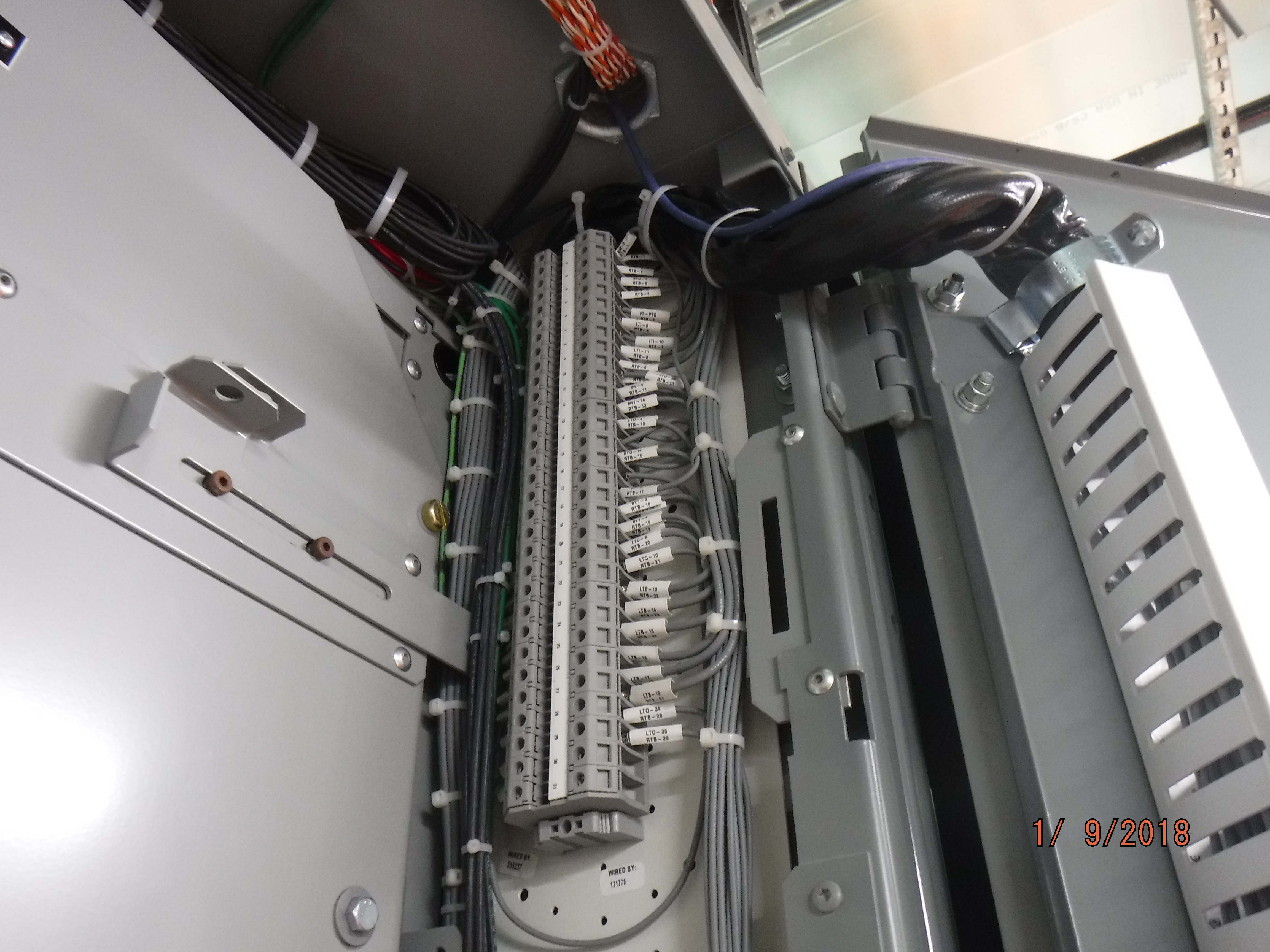
Use consistent strip and terminal IDs. SENTOP's guide to terminal numbering and labeling practices explains how the same identifier should survive from drawing to as-built record.

Work classification

Classify the commissioning task before selecting the test point

“Commissioning” includes very different work conditions. The terminal product cannot decide which work-control category applies.

Documentation review

Compare drawings, I/O lists, terminal schedules, cause-and-effect documents, product data, and test records without manipulating the circuit.

Deenergized verification

After the governing energy-control process, qualified personnel verify the exposed parts and test boundary as required. A terminal position is supporting information, not the proof.

Controlled functional test

Operate the circuit only within the approved test plan, simulation limits, protection and process safeguards. A low control voltage can still initiate hazardous motion or equipment states.

Energized diagnostic work

Treat this as a separate, exceptional work category. It requires the applicable justification, authorization, qualified persons, hazard controls, and circuit-rated test equipment.

In the United States, OSHA limits electrical testing to qualified persons and requires test instruments, leads, probes, and connectors to be visually inspected and rated for the circuit and environment. A terminal test socket does not make an energized measurement automatically authorized or safe.

Selection matrix

Choose the terminal family from the test objective

Start with circuit behavior, not color, width, or a generic “test terminal” label. Use the terminal block selection guide to check the wider function, conductor, rating, mounting, and approval inputs.

Commissioning taskUseful functional conceptRelease checks
Discrete 24 VDC fault localizationBasic or knife disconnect designed for the signal circuit.Source/common arrangement, input behavior, output safe state, remote start or motion consequence, test access, open-state label, and restoration.
Analog loop check or simulationTest-disconnect arrangement with documented field/panel-side access; shielding and isolation as designed.Signal type, polarity, loop supply, barrier/isolator, shield reference, allowed simulator connection, connected device limits, and procedure.
Fused field-supply commissioningFuse/component disconnect system coordinated with the protection design.Exact fuse and holder, available fault current, feed side, grouping temperature, indication, spare control, test point, and replacement status.
Insulation or continuity programDefined disconnect/test points that separate equipment the approved test must not stress.Test voltage/current, sensitive electronics, SPDs, communication ports, grounds, parallel paths, stored energy, discharge, and acceptance criterion.
Neutral-related verificationApproved neutral-disconnect arrangement only where the circuit and jurisdiction permit it.Load removed as required, shared/backfed neutral, source topology, marking, sequence, overvoltage risk, device instructions, and safe-work process.
Conventional CT metering/protection testDedicated CT test system with the required shorting, test, cover, and forced sequence.CT ratio/class/polarity, secondary continuity and ground, phase map, burden, relay/meter interface, responsible authority, and restored configuration.
Accessory control

The approved test interface is part of the BOM

A useful test point includes more than the terminal housing. The released bill of materials should preserve the exact test adapter or plug, disconnect link, bridge/shorting component, cover, seal, partition, marker, end hardware, operating tool, and any storage or replacement control.

In North American component work, UL 1059 terminal-block compliance does not by itself establish suitability in the finished panel. The exact circuit behavior, accessories, environment, Conditions of Acceptability where applicable, and industrial-control-panel evaluation still control the end use.

Do not insert a probe into a conductor entry, bridge channel, function shaft, or unmarked opening unless the exact manufacturer documentation identifies that use. A mechanically fitting accessory can have the wrong contact depth, voltage/current capability, touch protection, or measurement interface.

  • Match every accessory to the exact terminal family and catalog number.
  • Verify voltage, current, environmental, approval, and measurement limits for the complete path.
  • Show test-point orientation and access space in the panel layout.
  • Define normal storage and control for removable plugs, bridges, covers, and tools.
  • Protect against an accessory remaining installed after commissioning.

See SENTOP's guide to terminal block accessories, including test plugs and adapters, then keep exact compatibility in the BOM.

Technician identifying and tagging control wires in a substation switchgear cabinet
Control wires are identified and tagged inside a switchgear cabinet; commissioning records should tie temporary links, terminal positions, and final restoration to the approved drawings. Photo: MTA Capital Construction Mega Projects / Wikimedia Commons, CC BY 2.0. The photo does not establish that the shown terminals are disconnect/test types or reveal their electrical state.
Eight-stage control

Commission the point, preserve the evidence, and prove restoration

This is a documentation and planning workflow for qualified teams. It does not replace the site-specific electrical-safety procedure or authorize energized work.

Freeze the source package

Use one approved revision of the schematic, terminal schedule, I/O list, cause-and-effect documents, panel layout, BOM, device data, and test procedure. Stop if the installed terminal function differs.

Identify the complete circuit

Map field and panel sources, backfeed, common/neutral, protective and functional earth, shield, stored energy, remote control, motion, and connected equipment—not only the terminal number.

Classify the work condition

Separate documentation review, deenergized verification, functional testing, and energized diagnostics. Apply the correct energy-control, permit, hazard, PPE, and qualified-person requirements.

Verify the physical assembly

Confirm exact terminal and accessories, rail position, marker, bridge or shorting path, cover, partition, test-side orientation, wire access, and the manufacturer's current instructions.

Establish the approved test state

Record the starting state and the authorized temporary state. For specialized transformer circuits, use only the forced sequence and matched system specified by the released design.

Perform and capture the defined test

Use approved, circuit-rated equipment and the stated acceptance criteria. Tie every result to the terminal ID, circuit side, procedure, instrument record, document revision, and responsible person.

Resolve exceptions without improvisation

Localize the failed boundary, retain the evidence, quarantine unsafe or uncertain states, and use the controlled corrective-action process. Do not create undocumented jumpers or wiring changes.

Restore, independently check, and hand over

Return links, knives, plugs, fuses, covers, bridges, shorts, grounds, and control states to the approved configuration. Record the check and synchronize the as-built package.

Two electrical workers reviewing lockout tagout procedures
Workers review lockout/tagout procedures; applying a tag or discussing a procedure does not by itself verify absence of voltage at the terminal strip. Photo: NAVFAC / Wikimedia Commons, U.S. federal public-domain work.
Electrical-safety boundary

A visible open blade is not an absence-of-voltage test

A disconnect element can help define a local circuit boundary, but it cannot identify all energy sources, control stored energy, prevent remote restart, establish upstream lockout, or prove every exposed part is deenergized. Indicators and status lights are also supporting information—not the required verification.

OSHA 29 CFR 1910.333 requires U.S. workplace circuits and equipment to be disconnected from electrical energy sources unless an exception applies and requires a qualified person to verify deenergization at exposed parts with appropriate test equipment, including checking induced voltage or unrelated backfeed. Other jurisdictions and sites have their own governing rules.

Treat the terminal as not a load-break device unless the exact product evidence says otherwise. It can form part of an engineered boundary only when the exact device, evaluation/listing, lockability, circuit ratings, and governing procedure support that use—and required absence-of-voltage verification still applies.

State record

Make every temporary state traceable

A technically correct test can still leave a panel unsafe or unavailable if a link, fuse, cover, short, or control state is not restored. Use record fields that make the next qualified person's decision unambiguous.

Record fieldWhat to captureWhy it matters
Circuit identityStrip/terminal ID, function, from-to reference, field/panel side, drawing sheet/grid, revision, and device tag.Prevents work on a similar adjacent point and preserves drawing-to-panel traceability.
Installed productManufacturer, exact catalog number, conductor, accessories, bridge/shorting system, cover, fuse/component, and normal marker.Stops a generic terminal description from hiding a function-changing substitution.
Energy and test boundaryKnown sources, backfeed/stored-energy paths, work classification, permit/procedure, test side, connected equipment, and restrictions.Separates terminal convenience from the governing work-control decision.
Initial, test, and restored statesKnife/link/plug/fuse/bridge/short/ground/control state, I/O force, software override, and bypass before, during, and after the activity.Creates a deliberate restoration requirement instead of relying on memory or a photo.
Method and acceptanceProcedure step, instrument/test-set identification, calibration status where required, applied limits, result, criterion, and reviewer.Makes the result repeatable and reviewable rather than a loose meter value.
Exception and handoverDefect/nonconformance number, temporary-state authorization, warning, responsible owner, due action, and service restriction.Prevents an unfinished circuit from disappearing into final energization or turnover.

Build the position and accessory data from the released drawing using SENTOP's guide to building a terminal-strip BOM from an electrical drawing. Keep spare positions distinct with the spare-terminal planning guide.

Special secondary circuits

CT, VT/PT, and low-power sensors need different test logic

Do not apply one transformer-test sequence to every secondary circuit. Identify the sensing technology, approved secondary configuration, grounding point, connected device, and governing test system before selecting a terminal or plug.

Shorting and grounding are separate controls. Preserve the designated instrument-transformer secondary grounding point. Do not create an unintended second ground or lift a required ground; temporary shorts or grounds belong only at locations identified by the approved drawing and procedure.

Current transformers mounted at the back of an electrical cabinet
Current transformers in a cabinet illustrate why CT secondary circuits require a dedicated documented test sequence and approved shorting/disconnect hardware. Photo: FearChild / Wikimedia Commons, public domain. The image does not show a CT test block or establish any secondary state.
Conventional inductive CT

Never open the secondary while primary current can flow

An open conventional CT secondary can develop hazardous voltage and damage equipment. Use only the exact approved shorting/test assembly and its forced or make-before-break sequence. The design must show which contacts short first, which path opens next, and how normal continuity is restored.

Voltage / potential transformer

Never short-circuit the VT/PT secondary

VT/PT secondary behavior is the opposite of the conventional CT rule. Isolate and protect it only as the transformer, protective device, test switch, and procedure specify. Do not repurpose a CT shorting scheme for a voltage circuit.

Rogowski / LPCT / digital sensor

Identify the interface before applying CT habits

Low-power current sensors, Rogowski coils, and digital instrument-transformer interfaces behave differently and may not require conventional CT shorting. Do not short or ground an output unless the exact sensor and receiving-equipment instructions require it.

A product described as a CT test terminal is not safe by name alone. Use a matched terminal, bridge, plug, cover, and sequence documented for the exact system. Manufacturer examples from Weidmüller and Phoenix Contact illustrate make-before-break and leading short-circuit functions; they are not universal operating instructions.

Method boundaries

One test port does not authorize every measurement

Continuity

Confirm only the defined deenergized path

A continuity result does not prove insulation condition, conductor ampacity, polarity, CT safety, grounding integrity, or absence of hazardous voltage. Parallel paths can also mask an open circuit.

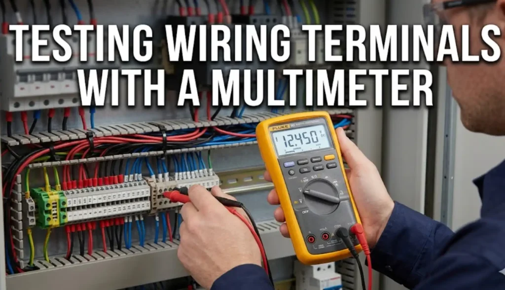
For generic diagnostic checks after the work condition and circuit are established, see how to test a terminal block with a multimeter. That guide does not convert a normal terminal into an approved disconnect/test point.

Insulation

Protect connected electronics before any test voltage

Do not blindly apply an insulation-resistance or withstand test through I/O, relays, meters, SPDs, communication modules, barriers, sensors, or trip units. Use the equipment instructions and approved test plan; no universal voltage or pass value belongs in a terminal article.

Loop test

Define supply, polarity, isolation, and process effect

Signal simulation can energize an input, drive an output, defeat an interlock, or create a false process state. Coordinate the control-system mode, alarms, inhibit/bypass control, and field effect before connection.

Live diagnostic

Use only under the governing energized-work controls

Instrument category, voltage, current, leads, probe exposure, environment, approach, PPE, and authorization all matter. A socket's presence does not lower the circuit hazard by itself.

Digital multimeter performing a continuity test on a loose wire
A continuity check demonstrates only the tested path under the stated setup; it does not prove insulation integrity, polarity, CT shorting, or absence of hazardous voltage. Photo: MinhVN123 / Wikimedia Commons, CC0 1.0. This is a loose-wire example, not terminal-block commissioning.
Failure prevention

Eight commissioning shortcuts that create hidden risk

Each failure disconnects the physical terminal state from the circuit evidence or work-control process.

01

Open equals safe

A local disconnect is mistaken for LOTO or absence-of-voltage verification. Apply the governing energy-control process and verify exposed parts as required.

02

Nominal current equals load-break rating

The terminal is opened under a condition its product data does not authorize. Confirm operating duty and circuit state before manipulation.

03

Any opening becomes a probe socket

A lead is inserted into a conductor entry or accessory channel. Use only the identified interface and matched, circuit-rated accessory.

04

Generic signal terminal used for CT

The conventional CT secondary loses continuity. Use the dedicated short-before-open system and responsible protection/metering procedure.

05

CT shorting copied onto VT or sensor

Opposite or different output behavior is ignored. Identify CT, VT/PT, Rogowski, LPCT, or digital interface before defining the test state.

06

Neutral or PE treated as a signal

A hazardous shared neutral or protective-bonding path is interrupted. Use only a design- and rule-specific arrangement with a qualified procedure.

07

Temporary link escapes documentation

A bridge, fuse, plug, short, ground, or bypass remains after the test. Record each temporary item and require independent restoration verification.

08

Late substitution changes the function

The rail no longer matches the BOM, drawing, marker, or accessory system. Recheck exact model data and revise every controlled deliverable before acceptance; visibly damaged or functionally uncertain terminals belong in a controlled replacement review.

Technician testing an electrical panel in a substation
Electrical-panel testing in a substation; the actual test method, limits, and energized-work controls come from the approved commissioning plan. Photo: MTA Capital Construction Mega Projects / Wikimedia Commons, CC BY 2.0. The photo does not establish a terminal-block, CT-secondary, or absence-of-voltage test.
FAT, SAT & handover

Close commissioning with an evidence package, not a visual glance

Terminal matchExact catalog number, function, position, conductor, accessories, and markers agree with the approved BOM and layout.
State matchEvery knife, link, plug, fuse, bridge, short, ground, cover, and control mode is in the approved handover state.
Drawing matchSchematic, terminal schedule, I/O list, marker data, bridge chart, panel layout, redlines, and as-built revision agree.
Test evidenceProcedure, boundary, instrument/test set, acceptance criteria, result, exceptions, reviewer, and date are traceable.
Safety closureTemporary work controls, bypasses, tags, warnings, service restrictions, and outstanding defects follow the site handover process.
Future serviceInstructions, spare accessories, storage, replacement control, and normal-state diagrams are available to the owner.

If physical wiring work is required after a failed check, follow the exact product instructions and SENTOP's separate guide to wiring a terminal block safely. Coordinate the result with the wider control panel wiring guide.

Procurement handoff

Send enough information to match the terminal and the test function

A useful quotation should identify the circuit, state logic, test accessory, documentation, and target market—not only a width, color, or “test terminal” description.

Circuit and taskApplication, circuit type, voltage/current, test objective, field/panel boundary, normal/test/restored states.
Conductor and layoutMaterial, class, cross-section/AWG, ferrule, conductor count, rail, duct, access, partitions, orientation, and labels.
Functional categoryKnife, test-disconnect, fuse/component, neutral, CT/VT, shield/FE, or another explicitly defined function.
AccessoriesTest plug/adapter, bridge/short, link, cover, seal, fuse/component, marker, end plate/stop, and operating tool.
Project evidenceSchematic, terminal schedule, I/O list, cause/effect, panel layout, BOM, procedure, applicable standard, and approval need.
Commercial dataQuantity, samples, destination, delivery, repeat-order control, OEM labeling/packing, and required documents/certificates.
Related decisions

Use each guide for its own decision instead of turning commissioning into a generic terminal-selection or wiring article.

FAQ

Disconnect and test terminal block questions

These answers define selection and safety boundaries. The exact product and site procedure remain controlling.

What is a disconnect and test terminal block?

It is a functional terminal block that provides a defined circuit-separation point and, depending on the exact model, an approved test port, function shaft, bridge interface, component position, or other test-access feature. Product data controls its ratings, accessories, conductor combinations, and permitted operation.

Can opening a disconnect terminal make a circuit safe to work on?

Not by itself. An open terminal disconnect does not identify every source, control stored energy, lock an upstream isolator, prevent backfeed or restart, or verify exposed parts are deenergized. Follow the governing energy-control and verification process.

Is a disconnect terminal automatically rated to break load current?

No. Do not infer load-breaking duty from the terminal's nominal current or a movable knife. The exact product instructions and ratings must authorize the operating condition; otherwise establish the required deenergized state before operation.

What is the difference between knife-disconnect and test-disconnect terminals?

A knife-disconnect terminal provides a manually operated circuit break. A test-disconnect model combines separation with specified test access, but the ports, sides, adapters, bridges, and conditions vary. The exact catalog data decides the difference.

Can any terminal opening be used as a test point?

No. Use only the test ports, function shafts, plugs, adapters, and connection methods identified for the exact terminal. A conductor entry, bridge channel, or unmarked opening may not be safe or rated for a probe.

Why do conventional CT test circuits need special terminals?

A conventional current-transformer secondary must not be opened while primary current can flow. A dedicated CT test system can preserve continuity with an approved short-before-open or make-before-break arrangement, plus controlled bridges, covers, grounding, and restoration.

Are CT and VT/PT test sequences the same?

No. A conventional CT secondary must not be left open under primary current, while a voltage or potential transformer secondary must not be short-circuited. Use the exact transformer, protection, test-switch, and procedure documentation.

Should a Rogowski coil or low-power sensor be shorted like a CT?

Do not assume so. Rogowski coils, low-power current sensors, and digital interfaces have different output behavior. Identify the exact sensor and receiving device, then follow their instructions; do not short or ground the output by habit.

Should disconnect and test terminals appear on the drawings?

Yes. Show the exact function, designation, normal state, circuit side, approved accessories, and restoration or special test requirement in the schematic, terminal schedule, BOM, layout, label data, and commissioning record.

What should be checked before returning the panel to service?

Confirm every terminal, knife, link, plug, fuse, bridge, short, ground, cover, and control state is restored; verify drawings and test records agree; resolve or formally control every exception; then follow the site's reenergization and handover process.

Primary references

Standards, safety rules, and manufacturer evidence

Use the edition and requirements adopted for the project, the exact product certificate/instructions, and the completed panel or machine requirements. A standard's scope does not certify every terminal or application.

  1. IEC 60947-7-1:2025 — terminal blocks and specified test-disconnect terminal blocks for copper conductors within its scope.
  2. IEC 61869-2 — additional requirements for current transformers.
  3. IEC 61869-3 — additional requirements for inductive voltage transformers.
  4. UL 1059, Edition 6 — terminal-block component requirements and the end-product suitability boundary.
  5. UL 508A — industrial control panel requirements for the applicable North American evaluation path.
  6. OSHA 29 CFR 1910.333 — selection and use of electrical work practices.
  7. OSHA 29 CFR 1910.334 — use and inspection of test instruments and equipment.
  8. OSHA interpretation on indicators — an open-position indicator does not replace qualified-person verification of deenergization.
  9. ABB current and voltage instrument-transformer instructions — CT open-circuit, VT short-circuit, and secondary grounding cautions.
  10. Schneider Electric CT shorting-block guidance — hazards of opening a conventional CT secondary under primary current.
  11. Weidmüller test-disconnect connection conditions — model-system features including CT make-before-break arrangements.
  12. Phoenix Contact transformer terminal blocks — model-specific leading short-circuit and test-system concepts.
  13. WAGO 280-868 disconnect/test terminal — one exact product example with a pivoting knife disconnect and test port.
  14. Phoenix Contact UT 6-T-HV P/P — one exact test-disconnect example with product-specific function shafts and accessories.
From schematic to repeatable test access

Review the circuit function before releasing the terminal-strip BOM

Share the drawing, terminal schedule, I/O list, circuit ratings, conductor data, normal/test/restored states, target market, accessories, quantity, and commissioning tasks. SENTOP can review model matching, BOM completeness, documentation needs, and supply options.

滚动至顶部
