
How to Read Terminal Block Specifications (With Examples)
Read every value with its model, standard and conditions. This guide shows how to separate voltage systems, current test configurations, conductor formats, installation data, geometry and certification evidence before approving a terminal block.
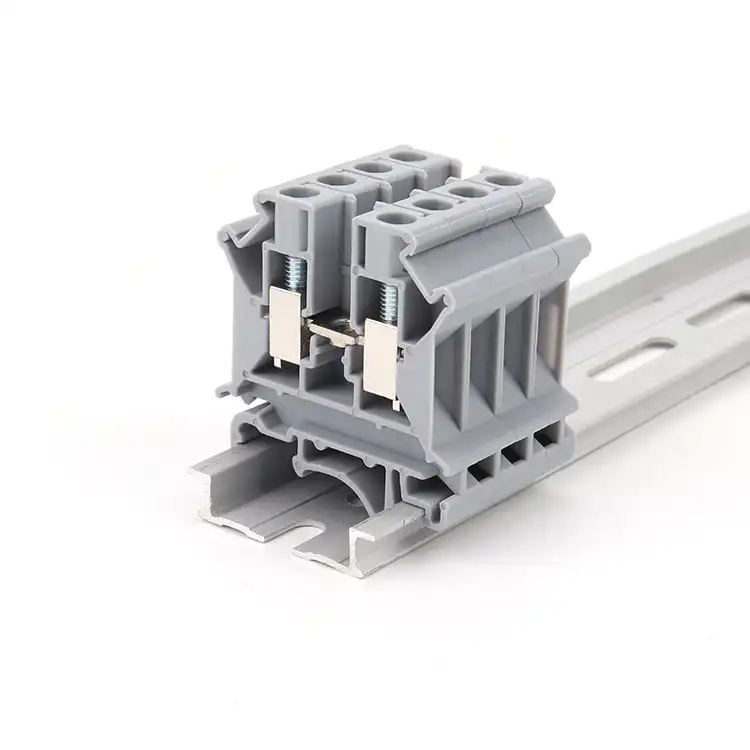
Read terminal block specifications in this order: applicable market and standard; voltage and current under the stated conditions; conductor type and range; connection, torque and strip length; mounting and dimensions; environmental limits; then exact-model compliance evidence.
A number without its row heading is incomplete
A datasheet is not one promise. It is a collection of values produced under different standards, conductor preparations, accessories and installation assumptions. The same catalog number may show an IEC nominal value, a UL Recognized value, a maximum load current tied to a larger conductor and a lower bridge current. All four can be valid without being interchangeable.
Start by writing the application requirement beside the candidate data—not by highlighting the largest number. Record the destination market, end-equipment rules, circuit function, conductor, mounting, environment and approval evidence you need. Then compare one row at a time. If a supplier proposes an alternative, the alternative must pass the same matrix.
Read six layers before making a decision
The reading order prevents a value from one model, standard or conductor condition being transferred to another.
Identity
Manufacturer, family, full catalog number, color suffix, revision and publication date.
Product function
Feed-through, PE, fuse, disconnect, multi-level, barrier, pluggable or PCB role.
Rating system
Standard, approval column, use group, overvoltage category, pollution degree and notes.
Connection data
Conductor form, cross-section, ferrule, number of conductors, strip length and torque.
Mechanical data
Pitch, width, height, depth, positions, levels, pin or rail geometry and accessories.
Evidence
Current certificate record, file holder, exact covered model, declarations and test scope.
One exact model, several valid values
This public example demonstrates the reading method. It is not a cross-reference or equivalence claim for a SENTOP product.
Phoenix Contact PT 2,5 · item 3209510
Public product data accessed for this guide; always check the latest manufacturer page and approval record.
One position, two connections, one potential; NS 35/7.5 or NS 35/15 mounting.
Nominal current is stated at the 2.5 mm² nominal cross-section.
Explicitly tied to a 4 mm² rigid conductor—not a generic short-duration peak.
The approval data identifies 26–12 AWG for the stated UL Recognized rating.
Rigid, flexible, ferruled, twin-ferrule and directly pluggable rows are not identical.
The value belongs to this model and connection design; it is not a family-wide default.
The lesson: do not combine 800 V from one row, 30 A from another row and a 2.5 mm² ferruled conductor from a third row into an imaginary “800 V / 30 A / 2.5 mm²” rating.
Voltage fields describe different insulation questions
Copy the label, value, unit, standard and conditions together. Do not rename fields to make comparison easier.
Nominal or rated voltage
Use the exact wording and rating system shown. Compare it with the circuit and end-equipment requirement only after checking the relevant standard, category and conditions.
Rated insulation voltage
This is an insulation-coordination reference value where the applicable standard uses it. It does not automatically authorize continuous operation at the same voltage.
Rated impulse withstand voltage
This addresses specified transient overvoltage withstand and insulation coordination. It is not a continuous working-voltage rating.
Dielectric or test voltage
A laboratory test setpoint and duration are evidence of a defined test. They should never be copied into the application-voltage field.
A current rating belongs to a test configuration
Do not apply a universal derating percentage. Find the conductor, loading, accessory and temperature conditions behind the exact value.
Current creates resistive heating at the conductor and contact. That is why conductor size, contact resistance, adjacent loading, ambient conditions and heat removal matter together.
Referenced conductor
Record the material, rigid or flexible construction, cross-section and preparation used for the published current.
Temperature-rise basis
Read the test requirement and ambient/operating notes. A material temperature index is not a current derating curve.
Grouping and enclosure
Check any multi-pole, adjacent-load or enclosure conditions supplied by the manufacturer or required by the end equipment.
Accessories and bridges
Jumpers, fuse elements, disconnect parts or plug/header interfaces may carry a different current limit from the base block.
A published comparison from Phoenix Contact illustrates the different test contexts: its overview describes five terminals at approximately 20 °C with a 45 K maximum rise for IEC 60947-7-1, versus three terminals at 25 °C with a 30 K maximum rise for UL 1059. Use the applicable standard data—not a fixed UL/IEC conversion factor. Review the test overview.
If the datasheet has no usable derating curve for your installation, ask for model-specific data and perform the end-product thermal evaluation required by your design process. Do not invent a curve from a similar family.
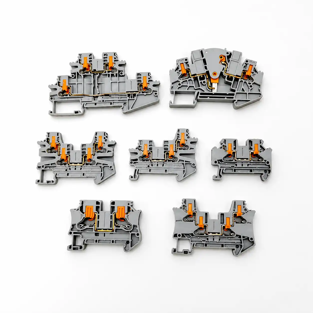
“Wire range” is usually several separate ranges
AWG and mm² are different systems, not round equivalents. More importantly, the clamp may publish different limits for rigid, flexible, ferruled, twin-ferrule and directly inserted conductors. Treat each row as a separate permission.
- Rigid / solid: confirm material, cross-section and whether direct insertion is permitted.
- Flexible / stranded: check strand class, actuation method and whether bare insertion is allowed.
- Ferrule without sleeve: verify ferrule body and crimped cross-section.
- Ferrule with plastic sleeve: the collar can change the usable maximum.
- Two conductors: only use one terminal point for two wires when an exact row permits that combination.
- AWG and mm²: use the ranges published for the model; never approve by mental conversion alone.
Read the value together with the operating method
Screw, spring and push-in systems use different instructions. Do not transfer torque, strip length, ferrule practice or tooling between them.
- Connection technologyScrew clamp, spring cage, push-in, insulation displacement, crimp or plug/header interface.
- Strip lengthUse the exact millimeter or inch range and inspect that copper is fully captured without protrusion.
- Tightening torqueApply only to the specified screw point using the manufacturer value and an appropriate controlled tool.
- Actuation toolConfirm screwdriver blade, push button or release opening and the sequence for inserting flexible conductors.
- Reconnection rulesCheck mating cycles, conductor reuse, re-torque and maintenance instructions instead of applying shop habit.
- Accessory methodUse compatible bridges, end plates, markers, test plugs and covers from the released system.
Pitch is one dimension—not the whole footprint
Use the dimensional drawing, mating view and mounting information. A product photo is not a scale drawing.
A 12-position footprint has 11 intervals. Changing from 5.00 mm to 5.08 mm creates a 0.88 mm difference from first pin center to last—not a harmless 0.08 mm total.
Pitch and positions
Confirm center-to-center pitch, number of positions, pin numbering and first-pin orientation.
Overall envelope
Check width, height, depth, cover movement, wire bend radius and access for tools.
Mounting interface
Verify PCB footprint, panel holes, rail profile such as NS 35/7.5 or NS 35/15, and end-clamp space.
Connection map
Do not equate positions, connections, levels and potentials. Use the internal diagram to identify conductive paths.

Pitch does not establish voltage rating. Clearance and creepage depend on the exact conductive geometry, insulation system and applicable coordination rules—not simply the center spacing.

Positions, connections, levels and potentials are not synonyms
A single modular feed-through block can be one position with two conductor connections and one electrical potential. A multi-level block can place more than one isolated or bridged function above the same rail position. A fixed strip can have several positions in one molded body.
- Position or pole: confirm how the manufacturer counts repeating circuit locations.
- Connection: a physical conductor entry or termination point.
- Level: a vertically stacked connection tier.
- Potential: an electrically common node or path.
- “Way” or “contact”: marketplace terms can be ambiguous; require a drawing.
Read the condition behind every material claim
Material class, product construction, ambient limits and the final enclosure answer different questions.
Operating, assembly and storage temperatures
These ranges may differ. Determine whether an operating range includes self-heating, whether a short-term maximum is separately limited and which temperature applies during conductor actuation.
UL 94 flammability class
V-0, V-1, V-2 and other classifications come from defined small-scale specimen tests. V-0 does not mean “non-flammable,” and a material classification alone does not approve the complete product or enclosure.
Pollution degree and overvoltage category
These are insulation-coordination inputs tied to the intended micro-environment and supply context. Do not assign them from industry type or enclosure appearance alone.
Vibration, corrosion and ingress
Look for a named test, level and model scope. Do not infer vibration suitability from spring connection or transfer an enclosure IP rating to an unsealed terminal block.
A logo is a starting point—not the verification
Confirm that the exact catalog number is covered, the record is current and its ratings and conditions match the end use.
Identify the product standard
IEC 60947-7-1:2025 covers specified supported terminal blocks and test-disconnect blocks for copper conductors. Do not assume it covers every connector called a terminal block.
Verify UL status
Use UL Product iQ to match catalog number, file, category, ratings and Conditions of Acceptability.
Distinguish Recognition
A UL Recognized Component is evaluated for use within a larger certified end product under stated conditions. It is not the same as a standalone UL Listed product.
Check market documents
Where applicable, request an exact-model EU Declaration of Conformity and current product-specific RoHS/REACH information. A generic “CE certificate” or logo is not enough.
Turn a dense datasheet into an approval record
Use the same order for every candidate so engineering, procurement and quality compare the same evidence.
- Freeze identityCatalog number, suffix, color, revision and publication date.
- Define applicationMarket, end equipment, circuit, mounting and environment.
- Select the rating columnStandard, category, use group and stated conditions.
- Check voltage termsKeep operating, insulation, impulse and test values separate.
- Check current basisConductor, temperature rise, grouping, accessory and derating notes.
- Match the conductor rowRigid/flexible, AWG/mm², ferrule, quantity and preparation.
- Release installation dataStrip length, torque or actuation, tool and accessories.
- Verify mechanical fitPitch, envelope, levels, potentials, rail/PCB and mating direction.
- Archive evidenceDrawing, datasheet, database record, declarations and approved deviations.
Six shortcuts that create false compatibility
Choosing the largest rating
The largest value may belong to another standard, conductor, use group or test condition. Select the applicable row, not the marketing maximum.
Equating AWG and mm²
Manufacturers may publish both accepted ranges; that does not make the endpoints mathematically identical or every preparation interchangeable.
Guessing a derating percentage
Use the exact manufacturer data and end-product thermal evaluation. A curve from a similar block is not evidence for the candidate model.
Using pitch as a voltage class
Pitch helps define geometry. Rated voltage and insulation coordination depend on the complete conductive and insulating construction.
Copying torque by screw size
The same thread size can appear in different clamp designs. Use the exact product instruction and specified torque range.
Trusting a family-level logo
Verify the exact catalog number and conditions in the issuing body’s record and keep that evidence with the released BOM.
Send the requirement and the evidence gap
A useful model-matching enquiry shows what is fixed, what can change and which documents must be supplied.
Send with your enquiry
- Existing model number, datasheet, product photo or dimensional drawing
- Destination market, end equipment and applicable standard
- Circuit voltage/current and conductor material, type, size and preparation
- Connection method, positions/levels, pitch, rail or PCB footprint
- Environment, enclosure context and any vibration/corrosion requirement
- Required accessories, marking, quantity, packaging and destination
- Required certificate record, declarations, drawing and test/inspection evidence
Require in the response
- Exact proposed catalog number and documented deviations
- Applicable voltage/current row and its standard/conditions
- Conductor rows, strip length, torque or actuation instructions
- Mounting drawing, dimensions and compatible accessory list
- Current model-level certification and material/environmental documents
- Sample plan, MOQ, price, packaging and model-specific availability
- Production-ready and shipping dates in the formal quotation
Convert a datasheet into a controlled model request
SENTOP supplies multiple terminal block families and can review model numbers, photos, drawings or BOMs against conductor, circuit, mounting and accessory requirements. Final ratings, document availability, MOQ, samples, stock and lead time must be confirmed for the exact model and order.
- Keep the original and proposed datasheets side by side.
- Mark every deviation instead of relying on “equivalent” wording.
- Approve the sample, drawing and accessory BOM to the same revision.
- Put exact ratings, documents and substitutions into the quotation and PO.
Need help matching an exact terminal block model?
Share the current datasheet, model number, photo, drawing or BOM together with your conductor, circuit, mounting, accessory, document and quantity requirements.
Related specification resources
Terminal block specifications FAQ
Which terminal block specification should I check first?
First identify the exact catalog number, application, destination market and applicable standard. Then compare electrical ratings, conductor data, installation method, physical fit, environmental limits and exact-model evidence. Starting with the largest voltage or current number can put you in the wrong rating column.
Are UL and IEC terminal block ratings interchangeable?
No. Use the rating evaluated under the standard, product category and conditions applicable to the final equipment. Keep UL, CSA, IEC and other approval rows separate, and verify the exact catalog number and Conditions of Acceptability where relevant.
Is rated insulation voltage the same as usable working voltage?
No. A rated insulation voltage is an insulation-coordination reference where the applicable standard uses it; it does not automatically authorize continuous operation at that voltage. Use the relevant operational or nominal rating and the finished equipment requirements.
How should I interpret a terminal block current rating?
Read the current together with the referenced conductor, standard, temperature-rise basis, loaded-pole or grouping condition, accessory limits and any manufacturer derating data. “Maximum load current” may be tied to a larger conductor and should not be assumed to mean a short-duration peak.
Does one wire range cover solid, stranded and ferruled conductors?
Not necessarily. Many datasheets publish separate rows for rigid, flexible, ferruled, twin-ferrule and directly inserted conductors, and the maximum can change with preparation. Use the exact row that matches the installed conductor.
Is terminal-block pitch enough to confirm mechanical fit?
No. Pitch is only the center-to-center spacing. Also verify the number of intervals, overall width, height and depth, mounting interface, PCB pin or panel-hole geometry, wire-entry direction, tool access, mating parts and accessory space.
How can I verify a terminal block certification?
Match the exact catalog number to the issuing body’s current database or certificate, then record the file holder, product category, ratings and conditions. A company certificate, family-level logo or mark on a similar model is not enough.
What should I send SENTOP for model matching?
Send the existing model or datasheet, photos or drawings, destination market, voltage/current requirements, conductor details, connection and mounting method, positions or pitch, quantity, accessories, required documents, packaging and destination. Final suitability and commercial terms must be confirmed for the exact proposed model.
Primary sources used in this guide
- Phoenix Contact PT 2,5, item 3209510
- Phoenix Contact UK 2,5 B BU, item 3001048
- Phoenix Contact terminal-block electrical test overview
- IEC 60947-7-1:2025 official scope
- IEC 60664-1:2020 insulation-coordination scope
- UL 1059, Sixth Edition—Terminal Blocks
- UL Component Recognition classification
- UL Product iQ certification database
- UL 94 plastics flammability test overview
- IEC 60715:2017 standardized mounting rails
- European Commission CE marking guidance
This guide is an educational reading framework, not an electrical design approval, certification decision or installation instruction. Always use the exact current datasheet, drawing, manufacturer instructions, applicable certification record, end-equipment requirements and qualified engineering review.
