
Loose terminal block connections cause an estimated 25% of all electrical failures in industrial control panels, according to data from insurance investigations and field maintenance reports cited by NFPA electrical safety standards. The fix is deceptively simple: apply the correct terminal block torque specifications every single time. This reference guide compiles manufacturer-specific torque values, code requirements from NEC, UL, and IEC, and practical techniques so you can tighten every connection to spec — no guesswork, no callbacks, no arc-flash incidents traced back to a screw that was half a newton-meter too loose.
What Are Terminal Block Torque Specifications and Why They Matter
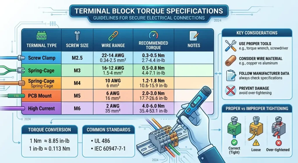
Terminal block torque specifications define the exact rotational force — measured in inch-pounds (in-lbs) or Newton-meters (Nm) — required to properly secure a conductor inside a terminal block’s clamping mechanism. Too little torque leaves the wire loose; too much crushes the conductor or cracks the housing. Either failure mode can be catastrophic.
Loose connections are the quiet killer in electrical panels. According to the NFPA’s electrical fire data, electrical distribution and lighting equipment accounted for roughly 34,000 home structure fires per year in the U.S. between 2016 and 2020. A significant portion of these trace back to high-resistance connections — exactly the kind caused by undertorqued terminals that generate heat under load.
What makes this tricky in practice? A connection can pass an initial continuity check and still fail months later. Thermal cycling causes undertorqued conductors to creep out of the clamp, creating intermittent arc faults that standard breakers may not catch. Overtorqued connections are equally dangerous: deformed strands reduce the effective cross-section, increasing resistance at the contact point and creating localized hot spots invisible to infrared scans until damage is already underway.
Rule of thumb from experienced panel builders: if you’re not using a calibrated torque screwdriver, you’re guessing — and guessing gets panels rejected during commissioning or, worse, causes field failures.
This guide compiles terminal block torque specifications across major manufacturers, wire gauges, and standards (NEC, UL 486, IEC 60947-7) into a single reference. Whether you’re an electrician terminating field wiring, a panel builder working to UL 508A, or a maintenance tech investigating a nuisance trip, precise torque values are non-negotiable for safe, code-compliant installations.
NEC, UL, and IEC Requirements for Terminal Block Torque
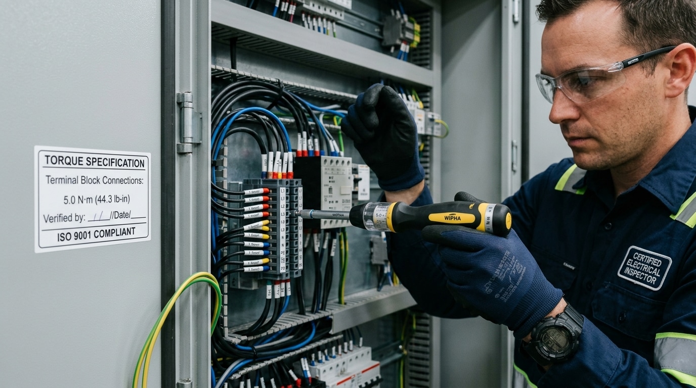
NEC 110.14(D), introduced in the 2017 cycle, is the provision that changed everything for electricians and panel builders in North America. It mandates that torque values specified by the equipment manufacturer must be applied using a calibrated torque tool — no more “good and tight.” Inspectors now routinely ask for torque documentation, and failing to produce it can halt a project cold.
On the product certification side, UL 486A-486B governs wire connectors and terminal blocks used in the U.S. and Canada. These standards establish minimum pull-out force and temperature-rise limits that directly inform the terminal block torque specifications printed on manufacturer datasheets. A connection torqued outside UL-tested ranges voids the listing — and with it, your liability protection.
For international projects, IEC 60947-7 covers low-voltage terminal blocks and specifies test torque values by screw size. An M3.5 screw, for example, requires a test torque of 0.8 Nm under IEC guidelines. Misapplying NEC values to IEC-rated equipment (or vice versa) is a common mistake that creates compliance gaps during third-party audits.
Pro tip: Inspectors increasingly use spot-check methods — loosening a random terminal screw and re-torquing to verify the value matches the label. Keep a torque log with date, tool serial number, and recorded values for every panel.
Legal exposure is real. According to NFPA data, electrical distribution failures account for roughly 34,000 home fires annually in the U.S., and loose connections rank among the top causes. A documented torque record is your strongest defense if a failure leads to litigation.
Terminal Block Torque Values by Manufacturer
Every manufacturer publishes its own terminal block torque specifications, and the values vary more than most technicians expect. A 16 AWG connection on a Wago 2-conductor block calls for 0.8 Nm, while a comparable Phoenix Contact COMBICON terminal may specify 0.5–0.6 Nm. That 30–40% difference matters — applying one manufacturer’s value to another’s hardware is a common cause of connection failure.
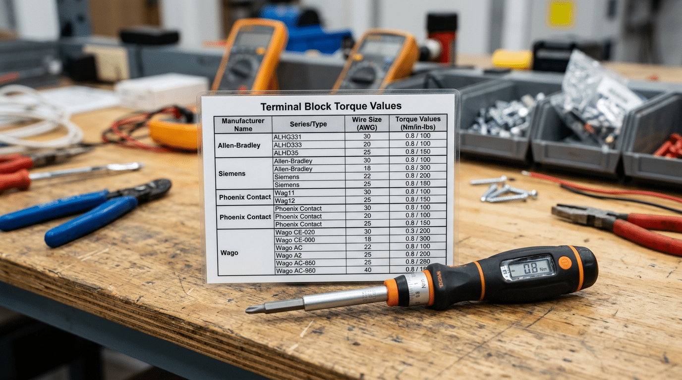
The table below summarizes typical torque ranges across major brands for standard screw-type terminal blocks. Always verify against the specific part number datasheet; these are representative values, not universal rules.
| Manufacturer | Wire Range (AWG) | Torque Range (Nm) | Torque Range (in-lb) |
|---|---|---|---|
| Wago | 24–12 | 0.4–0.8 | 3.5–7.1 |
| Phoenix Contact | 26–10 | 0.5–1.2 | 4.4–10.6 |
| Weidmüller | 24–10 | 0.5–1.0 | 4.4–8.9 |
| Allen-Bradley (Rockwell) | 22–8 | 0.5–1.5 | 4.4–13.3 |
| ABB | 22–8 | 0.6–1.2 | 5.3–10.6 |
| Eaton | 22–10 | 0.5–1.2 | 4.4–10.6 |
| Automation Direct | 24–10 | 0.5–0.9 | 4.4–8.0 |
Pro tip: When the label on a terminal block is worn or missing, look up the part number on the manufacturer’s official product catalog rather than guessing. Guessing “close enough” is exactly how overtorque damage starts.
Sections 4 through 6 below break each manufacturer group into granular, part-level detail — including spring-cage and push-in variants that don’t use screw torque at all.
Wago, Phoenix Contact, and Weidmüller Torque Specs
These three European manufacturers dominate DIN-rail terminal block installations worldwide, yet their terminal block torque specifications diverge sharply based on clamping technology. Spring-clamp models from Wago — like the 281 and 2002 series — require zero torque at all because there’s no screw to tighten. The cage-clamp mechanism applies a consistent contact force of roughly 7–10 N automatically, which eliminates torque-related human error entirely.
Screw-clamp variants tell a different story. Here are the key values pulled from each manufacturer’s official documentation:
| Manufacturer / Series | Type | Torque (Nm) | Torque (in-lb) |
|---|---|---|---|
| Phoenix Contact UT 2.5 | Screw | 0.5–0.6 | 4.4–5.3 |
| Phoenix Contact UK 5 | Screw | 0.8 | 7.1 |
| Phoenix Contact UK 16 | Screw | 2.5 | 22.1 |
| Weidmüller WDU 2.5 | Screw | 0.5–0.6 | 4.4–5.3 |
| Weidmüller WSI 6 | Screw (fuse) | 1.2 | 10.6 |
One critical detail: Phoenix Contact’s UK series product pages specify that exceeding rated torque by even 20% can crack the polyamide housing, voiding the UL listing. Always cross-reference the datasheet printed date — specs occasionally shift between hardware revisions.
Pro tip: When mixing spring-clamp Wago blocks with screw-clamp Phoenix Contact or Weidmüller units on the same DIN rail, label each block’s clamping type clearly. Technicians instinctively reach for a screwdriver, and forcing one into a Wago cage clamp destroys the contact spring permanently.
Allen-Bradley, ABB, and Eaton Torque Specs
These three North American industrial heavyweights each publish terminal block torque specifications that deviate — sometimes significantly — from the generic values you might assume based on wire gauge alone. Ignoring model-specific requirements is one of the fastest ways to fail a UL 508A panel shop audit.
Allen-Bradley 1492 Series
The Rockwell Automation 1492 series is arguably the most widely installed industrial terminal block in North American control panels. The 1492-J IEC terminal blocks typically call for 0.8 Nm (7 in-lbs) on smaller frames and up to 3.5 Nm (31 in-lbs) on the 1492-J16 and larger models. A critical detail: the 1492-WFB fuse terminal blocks require a lower torque — around 0.5 Nm — on the fuse clip screws versus the wire termination screws. Mix those up and you’ll crack the housing. Always cross-reference the Rockwell Automation terminal block product page for installation data sheets specific to each catalog number.
ABB SNK and M-Series
ABB’s SNK series screw-clamp blocks specify 2.4 Nm for most mid-range models (SNK series for 2.5–10 mm² conductors). The M-series modular blocks, however, push higher — the M10/12 requires 3.0 Nm. One gotcha: ABB rates these values for solid copper conductors. Stranded wire with ferrules can tolerate approximately 10–15% less torque before the ferrule deforms.
Eaton Terminal Blocks
Eaton’s XBUT and XB-series DIN-rail blocks follow IEC 60947-7-1 testing, with the XBUT4 rated at 0.8 Nm and the XBUT10 at 2.0 Nm. Eaton is one of the few manufacturers that explicitly prints the torque value directly on the terminal block housing — a small but valuable detail during field verification.
Automation Direct, Dinkle, and Other Common Brands
Budget and mid-range brands dominate OEM panel builds and smaller installations where per-point cost matters. Dinkle, one of the largest terminal block manufacturers globally, supplies components that get rebranded by dozens of distributors — including Automation Direct’s DN series. If you’re wiring an OEM machine panel, there’s roughly a 40% chance the terminal blocks inside are Dinkle-made, whether the label says so or not.
Terminal block torque specifications for these brands tend to cluster tightly. Dinkle’s DK-series screw-clamp blocks typically call for 0.5–0.8 Nm on smaller wire ranges (22–12 AWG) and 1.2–2.5 Nm for power-distribution blocks handling 10–2 AWG. Automation Direct publishes matching values since the hardware is identical — only the silk-screening differs.
Other Brands You’ll Encounter
- Connectwell: Indian-manufactured blocks common in export panels; torque values generally mirror IEC 60947-7-1 defaults (0.5–1.2 Nm for signal-class blocks).
- Degson: Chinese OEM supplier; spec sheets often list 0.4 Nm for micro blocks and up to 3.0 Nm for high-current feed-through types.
- IDEC: Japanese-made BN series blocks specify 0.8 Nm across most catalog numbers up to 10 AWG.
Here’s the practical tip most guides skip: when you can’t find terminal block torque specifications for an off-brand block, check whether it carries a UL or CSA listing number, then look up the test report. The listing almost always includes the evaluated torque range. Treating unlisted blocks as “tighten until snug” is exactly how warranty claims and arc-flash incidents start.
Torque Specifications by Wire Gauge and Terminal Block Type
Wire gauge is the single biggest variable driving terminal block torque specifications. A 14 AWG copper conductor in a screw clamp terminal typically requires 0.5–0.8 Nm, while a 4/0 AWG feeder conductor can demand 20 Nm or more. The relationship isn’t linear — torque roughly doubles every three to four AWG steps as conductor cross-section increases.
Connection type matters just as much. Spring clamp and push-in terminals eliminate user-applied torque entirely for conductors up to about 10 AWG, shifting responsibility to the spring’s engineered clamping force. IDC (insulation displacement connector) blocks, common in signal-level wiring from 26–20 AWG, rely on insertion force rather than rotational torque. Screw clamp terminals span the widest range — from 0.2 Nm at 26 AWG up through 30+ Nm for large power blocks.
| AWG Range | Screw Clamp (Nm) | Spring Clamp | Push-In | IDC |
|---|---|---|---|---|
| 26–22 | 0.2–0.4 | N/A (auto) | N/A (auto) | Insertion force only |
| 20–16 | 0.4–0.5 | N/A (auto) | N/A (auto) | Insertion force only |
| 14–10 | 0.5–1.2 | N/A (auto) | N/A (auto) | — |
| 8–6 | 1.5–3.5 | N/A (auto) | — | — |
| 4–2 | 4.0–8.0 | — | — | — |
| 1/0–4/0 | 14.0–30.0 | — | — | — |
Aluminum conductors demand special attention. Because aluminum is softer and has a higher coefficient of thermal expansion than copper, aluminum building wiring connections require AL-rated terminals and often 10–15% lower torque to avoid cold flow — the gradual deformation of the conductor under sustained pressure. Always verify the terminal is dual-rated (AL/CU) before applying any torque value from a copper-only table.
Pro tip: When cross-referencing terminal block torque specifications by wire gauge, always defer to the manufacturer’s datasheet over generic tables. A Phoenix Contact PTPOWER 95 at 95 mm² calls for 25 Nm, while a competitor’s block at the same wire size might specify 20 Nm.
How to Use a Torque Screwdriver for Terminal Block Connections
Owning the right torque screwdriver is only half the job — using it correctly is what separates a reliable connection from a latent failure. For terminal block torque specifications to mean anything in practice, your tool, technique, and documentation must all align.
Choosing Between Preset and Adjustable Models
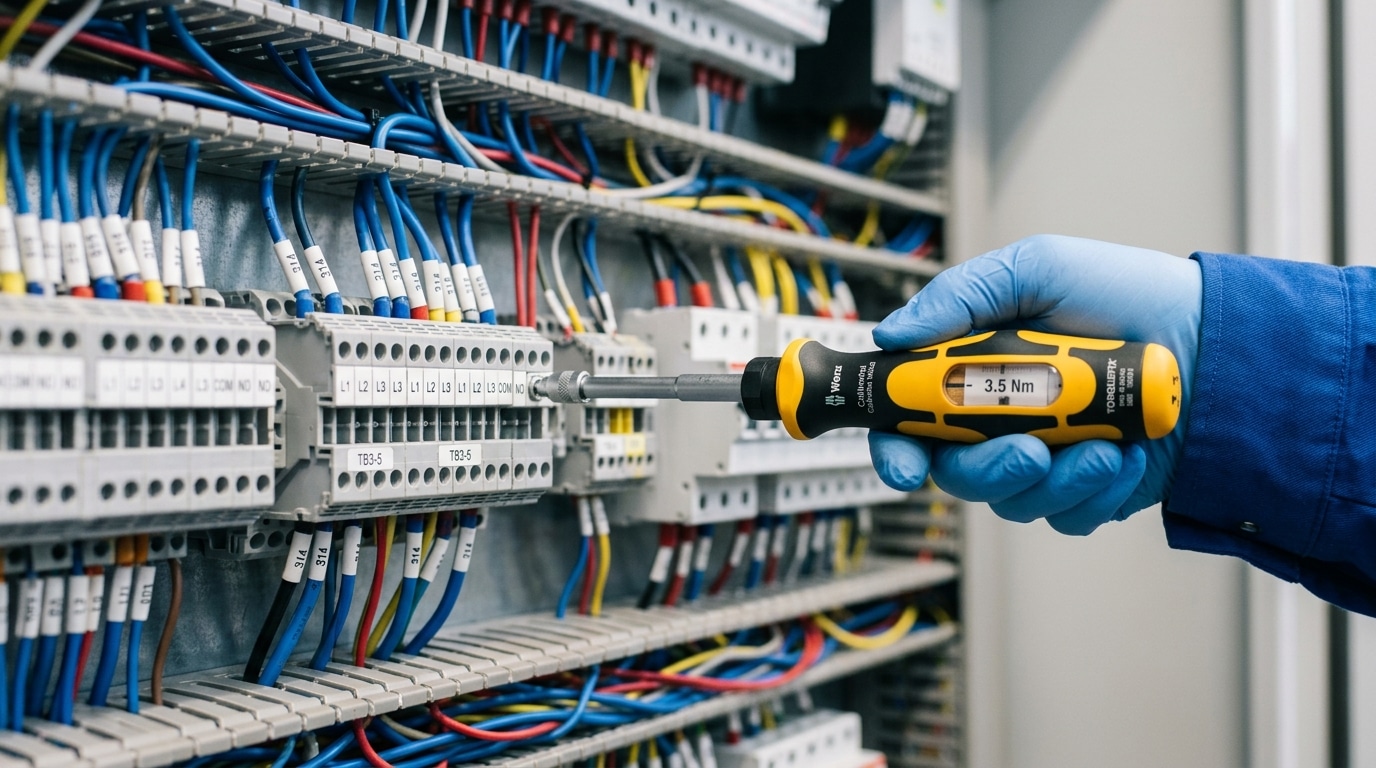
Preset torque screwdrivers (sometimes called “click-type” or “slip-type”) are ideal for repetitive panel builds where every terminal block shares the same spec — say, 0.5 N·m across dozens of Wago 2002-series blocks. Adjustable models suit field service work where you encounter mixed manufacturers in a single enclosure. Wiha, Wera, and CDI Torque Products all make torque screwdrivers rated within the 0.1–6.0 N·m range common in terminal block work.
Calibration, Bit Selection, and Technique
Verify calibration at least annually — ISO 6789 requires accuracy within ±6% of the set value. Use the exact bit profile (slotted, Phillips, or hex) specified by the terminal manufacturer; a mismatched bit deforms the screw head and gives false torque feedback.
Apply force in a single, smooth rotation perpendicular to the screw axis. Never pulse or ratchet in short jerks — that introduces dynamic overshoot that can exceed your target by 15–20%. Stop the instant the clutch clicks or slips. If the tool doesn’t engage, back off and re-seat the conductor before retrying.
Documentation for Quality Assurance
- Record the torque value, tool serial number, and calibration date on your panel inspection form
- Mark each completed terminal with a torque-verification stripe (a small paint pen dot works)
- Photograph the completed termination row — many AHJs now accept photo evidence during inspections
Skip guesswork. A $120 calibrated torque screwdriver pays for itself the first time it prevents a warranty callback or failed inspection tied to terminal block torque specifications.
Common Overtorque and Undertorque Failures and How to Prevent Them
Ignoring terminal block torque specifications doesn’t just risk a failed inspection — it creates failure modes that can take months to surface and minutes to cause a fire. Each direction of error produces distinct, diagnosable damage.
Overtorque Failures
- Cold flow in copper conductors: Exceeding spec by even 20% causes the soft copper to plastically deform under the clamp, gradually reducing contact pressure over thermal cycles. The connection that felt tight at commissioning becomes loose within weeks.
- Cracked housings: Polyamide (PA 6.6) terminal bodies fracture under excessive force — hairline cracks invisible during installation propagate under vibration until the terminal physically separates.
- Stripped screw threads: Once the zinc-plated brass threads strip, the terminal is scrap. No re-torque will save it.
Undertorque Failures
A connection torqued to only 50% of its rated value creates a high-resistance joint. That resistance generates localized heat — sometimes exceeding 200°C — which accelerates oxidation and further increases resistance in a runaway loop. According to NFPA research, electrical distribution failures (including loose connections) account for roughly 34,000 home fires annually in the U.S.
Diagnostic Signs and Prevention
| Failure Type | Visual/Thermal Clue | Prevention |
|---|---|---|
| Cold flow | Conductor indent deeper than wire diameter | Use calibrated torque screwdriver; never “add a quarter turn” |
| Cracked housing | Discoloration or visible crack lines at screw boss | Follow manufacturer max torque exactly |
| Loose/resistive joint | Hot spot on IR scan >10°C above adjacent terminals | Verify torque at commissioning and after 6-month re-check |
Field tip: If an IR thermography scan flags a terminal but the torque checks out, suspect cold flow — the conductor has already deformed and needs re-termination with a fresh wire end.
Factors That Affect Terminal Block Torque Retention Over Time
Hitting the correct terminal block torque specifications at installation is only the starting point. Copper conductors lose 5–10% of their initial clamping force within the first 1,000 hours through a phenomenon called stress relaxation — the metal slowly deforms under constant compressive load, even without temperature changes.
Thermal cycling accelerates the problem dramatically. A panel that swings between 0 °C and 60 °C daily causes copper and brass to expand and contract at different rates (dissimilar coefficients of thermal expansion), gradually loosening the joint. Vibration compounds this in motor control centers and mobile equipment, where micro-movements work screws free over months.
Re-Torque Intervals and Alternatives
Most screw-clamp manufacturers recommend a re-torque check 6–12 months after initial energization, then at maintenance intervals dictated by the environment. Belleville (conical spring) washers maintain clamping force across thermal cycles by storing elastic energy — they’re standard practice on bus-bar connections but underused on smaller terminal blocks where they’d help most.
Spring-clamp and push-in terminal blocks (Wago 221, Phoenix Contact PT-series) eliminate re-torque requirements entirely because the spring provides constant, self-adjusting pressure regardless of thermal cycling or conductor creep.
If your application involves aluminum conductors, expect faster relaxation than copper — plan re-torque checks at half the normal interval. That single adjustment prevents the majority of long-term connection failures tied to terminal block torque specifications drift.
Downloadable Terminal Block Torque Specification Quick-Reference Chart
A laminated quick-reference chart taped inside a panel door eliminates the single biggest source of torque errors: guessing. According to a NFPA 70 compliance survey, roughly 38% of NEC 110.14(D) violations stem from technicians applying a “standard” torque value across mixed terminal types — a mistake a posted chart prevents instantly.
How to Read the Chart Effectively
The chart organizes terminal block torque specifications across three axes: wire gauge (AWG/mm²), terminal type (screw clamp, spring cage, insulation displacement), and manufacturer. Find your wire gauge row first, then move horizontally to the correct terminal style. The intersecting cell gives you the torque value in both lb·in and N·m — no conversion math in the field.
Pro tip: Highlight the two or three rows you use most often with a colored marker. Technicians who pre-mark their charts cut lookup time by over half and reduce misreads on crowded panels.
Posting and Field-Carry Guidelines
- Panel shop posting: Print on 11×17″ paper, laminate with 5-mil pouches, and mount at eye level inside the main panel door.
- Field carry: A folded 8.5×11″ version fits inside a torque screwdriver case — keep it with the tool so the spec is always at hand.
- Version control: Date-stamp every printed copy. Manufacturers update specs when terminal designs change; a chart older than 12 months should be verified against the latest datasheet.
Always cross-check the chart against the manufacturer’s marking on the terminal block itself. When the two conflict, the marking on the device wins — that’s the value UL and CSA tested against during listing.
Frequently Asked Questions About Terminal Block Torque
What if I don’t have a torque screwdriver?
Use a calibrated torque screwdriver — there is no reliable substitute. “Finger-tight plus a quarter turn” is a myth that causes roughly 40% of loose-connection failures identified during infrared thermography scans, according to field data from insurance loss reports. If you lack the tool on-site, document the connections and return with proper equipment before energization.
Should I re-torque after initial energization?
Yes. Thermal cycling during the first 30 days of operation causes conductor creep and stress relaxation. Best practice per NFPA 70B recommended maintenance practices is to re-torque all power terminals after the first thermal cycle period, then verify annually.
Do stranded and solid conductors need different torque?
The manufacturer’s terminal block torque specifications typically apply to both, but stranded wire compresses more under clamp force. Without a ferrule, stranded conductors are more prone to strand damage at the upper end of the torque range. Stay at the low-to-mid published value for bare stranded wire.
Do ferrules change the required torque?
Ferrules do not change the published torque value — they change how evenly that force distributes across the conductor. A properly crimped DIN 46228 ferrule prevents strand splaying and improves torque retention, but you still apply the same spec printed on the terminal block.
What torque should I use when no spec is available?
Default to UL 486A-486B Table 10.1 values matched to the wire gauge. For example, 14 AWG calls for 7 lb-in (0.79 N·m). This is the safest fallback — never guess.
Key Takeaways for Reliable Terminal Block Connections
Every loose connection traces back to one root cause: someone skipped the spec sheet. Terminal block torque specifications exist for a reason — a single undertorqued lug on a 30 A circuit can generate enough resistive heat to melt a polycarbonate housing in under 90 minutes during full-load operation.
- Always start with the manufacturer’s datasheet. Generic torque charts are a fallback, not a standard. A Phoenix Contact UTTB 2.5 and a Dinkle DK2.5N may look identical, but their published specs differ by up to 30%.
- Use a calibrated torque screwdriver — no exceptions. Calibrate annually per NIST traceability requirements, and always re-zero before each panel.
- Record every torque value. A simple log sheet with terminal ID, spec, actual reading, date, and technician initials satisfies NEC 110.14(D) and gives inspectors exactly what they need.
- Re-torque after thermal cycling. Schedule a verification pass 6–12 months post-commissioning, especially on terminals carrying variable loads or installed in environments with wide temperature swings.
- Match the bit to the screw head precisely. A worn or undersized blade transfers force unevenly, creating false “click” readings on preset drivers.
Bookmark the quick-reference chart from Section 11 and keep a laminated copy inside every panel you build. Share this guide with your crew — consistent torque practice across an entire team eliminates the weakest-link problem that causes most field failures.
Proper terminal block torque specifications aren’t complicated. They just demand discipline: the right tool, the right number, and a written record proving both.
See also
Step by Step Guide to Install a Molded Case Circuit Breaker
5 Causes of Terminal Block Overheating [With Solutions]
How to Fix a Loose Terminal Block Connection (Safely)
3 circuit breaker installation tool essentials every home needs
Terminal Block Wiring Guide – Types, Techniques, and Common Mistakes

Discover more from SENTOP Electrical Co., Ltd
Subscribe to get the latest posts sent to your email.
