
Terminal Block Wiring Guide: Types, Steps and Safety Checks
To wire a terminal block, first de-energize the equipment and have a qualified person verify absence of voltage. Match the exact terminal and conductor, strip only the published length, operate its screw, spring or push-in clamp as instructed, then label and complete the required checks before controlled energization.
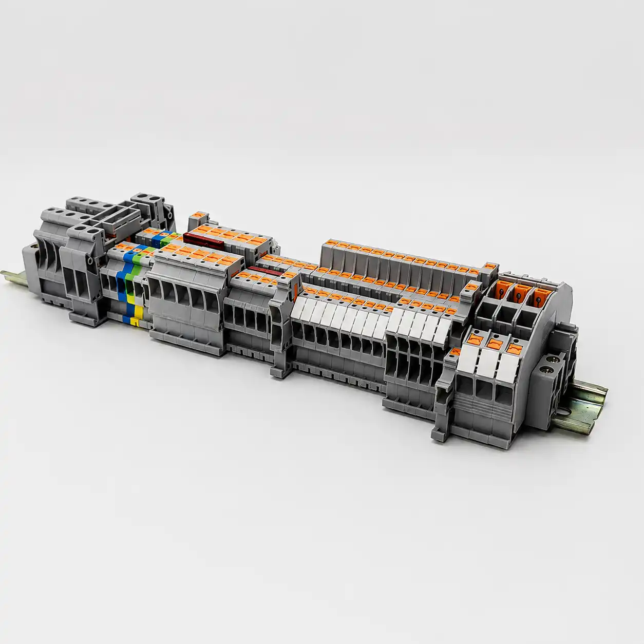
What does correct terminal block wiring require?
Correct terminal block wiring is a controlled chain: make the circuit safe, follow the approved schematic, verify the complete terminal-block part number and accessory system, prepare the permitted conductor, operate the clamp exactly as instructed, then label, inspect, test and record the finished connection.
Those details belong to the exact clamping unit and conductor configuration. A 2.5 mm² screw terminal and a 2.5 mm² push-in terminal can share a nominal size while requiring different preparation and tools.
This terminal block wiring guide focuses on common industrial and control-panel connections. It does not authorize live work or replace the electrical safety program, equipment instructions, panel standard, commissioning plan or local law. Barrier strips, PCB terminals, high-current distribution blocks, hazardous locations and utility systems can require different practices.
Why isolation comes before installation
For U.S. general industry, OSHA 1910.333 says exposed live parts should be de-energized before work unless its stated exceptions apply. De-energized circuits require the applicable lockout/tagout process, control of stored energy and verification by a qualified person using suitable test equipment, including checks for induced voltage or backfeed.
Do not use a push button, selector switch, extinguished LED or non-contact indicator as proof of isolation. Identify every source and follow the site procedure. Any energized diagnostic measurement is a separate qualified-person task under the applicable controls.
How to read a terminal block wiring diagram
Physical position is not enough. Build a traceable relationship between the drawing, terminal marker, conductor at both ends and the exact terminal function.
Start with the terminal designation.
A project may label a strip X1 and its positions X1:1, X1:2 and so on, but conventions vary. Read the drawing legend and revision rather than assuming a naming system. Trace each terminal to its field device and internal panel destination.
A basic feed-through terminal is commonly electrically continuous between its connection sides, but fused, disconnect, diode, sensor, multilevel and other functional terminals can have direction, switching or tier relationships. Follow the circuit symbol and product markings.
Choose the type before you prepare the conductor
Screw, spring-cage and push-in describe how the conductor is clamped. DIN rail, barrier and PCB describe mounting or product form. Feed-through, PE, fuse and disconnect describe circuit function. Keep those categories separate.
Screw connection
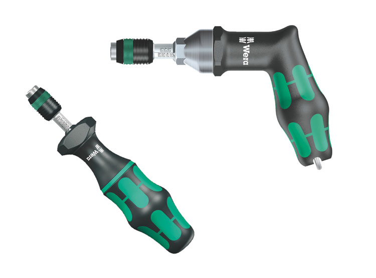
A screw moves a clamp, pressure plate or tension sleeve. The correct driver profile and exact tightening torque matter.
- Match solid, flexible and ferruled ranges separately.
- Use the published torque for that part.
- Do not add an automatic re-torque schedule without instructions.
Spring-cage connection
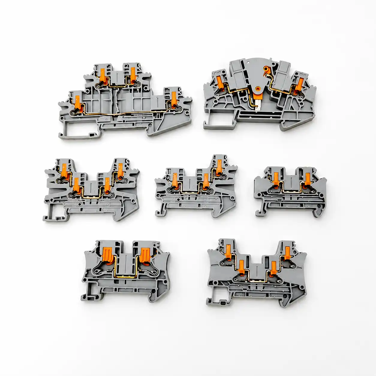
A lever, push button or operating slot opens the clamping point so the permitted conductor can be inserted or removed.
- Use only the intended operating point.
- Confirm bare and ferruled conductor ranges.
- Return the actuator to its operating position.
Push-in connection
Approved rigid or sufficiently stiff prepared conductors can insert directly. Other flexible conductors may require actuation.
- Check the directly pluggable range.
- Do not assume every stranded wire needs a ferrule.
- No connection screw means no installation torque.
| Format or function | What it means | Wiring consequence |
|---|---|---|
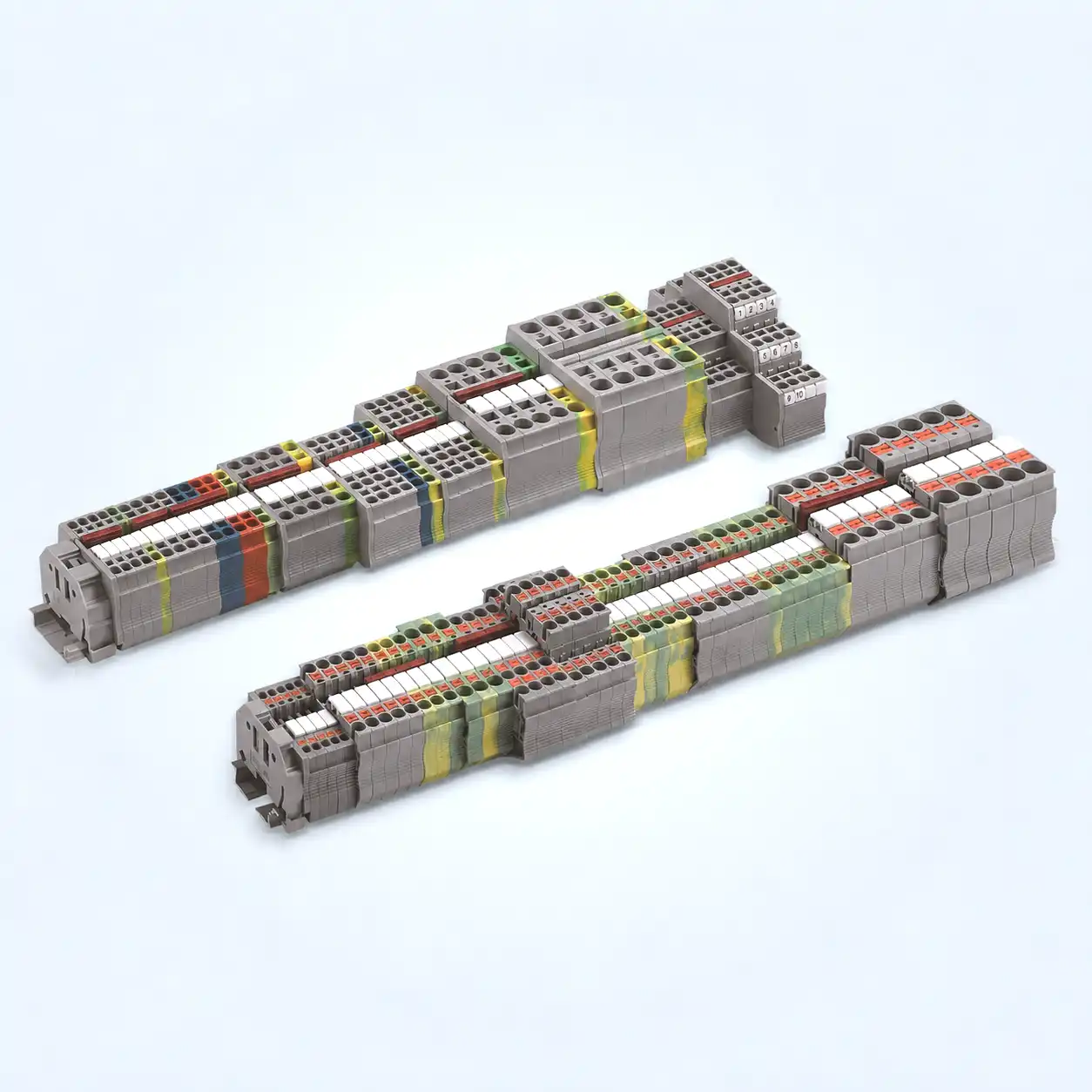
| DIN rail terminal | Modular component fixed to a specified rail profile | Complete the strip with compatible end brackets, end plates, bridges, partitions and markers. |
| Barrier strip | Surface-mounted row with physical barriers between positions | Use the stated lug or bare-wire method, screw hardware, covers and torque for the exact strip. |
| PCB or pluggable terminal | Board-mounted header, plug or fixed connection | Check pin layout, pitch, plug/header pairing, conductor entry and board-level ratings. |
| PE terminal | Protective conductor connection to an approved support or rail system | Verify the complete grounding path, rail, end brackets and required markings. |
| Fuse / disconnect / test | Functional terminal with an element in the current path | Follow orientation, switching state, fuse or test accessory and circuit-specific procedures. |
| Multilevel terminal | Two or more potentials stacked vertically | Match every tier to the diagram; never infer tier continuity from housing shape or color. |
Bring the data package, components and correct tools
The most important bench item is the information that defines the approved connection.
Freeze the connection design
- Approved schematic, terminal plan, wire list and current revision
- Exact terminal-block and accessory catalog numbers
- Current manufacturer datasheet and installation instructions
- Conductor material, class, cross-section and insulation data
- End brackets, plates, partitions, bridges, covers and markers
- Applicable panel, equipment, market and project requirements
Match the tool to the operation
- Site lockout/tagout equipment and required protective equipment
- Suitably rated test equipment for the qualified person
- Wire cutter and conductor-compatible stripping tool
- Specified screwdriver, bit, pusher or actuation tool
- Calibrated torque screwdriver where a torque is stated
- Approved ferrules, crimper and inspection criteria when used

How to wire a terminal block in 7 steps
Use this sequence as a framework. Insert the exact product and project instructions wherever a dimension, torque, test or acceptance value is required.
Identify, isolate, lock and verify every source
Determine what feeds the enclosure, circuit and auxiliaries. Apply the site energy-control procedure, control stored energy and prevent restart. A qualified person verifies the exposed circuit elements are de-energized with suitable test equipment.
- Account for control power, UPS, generators, capacitors and backfeed.
- Do not use a push button, selector or interlock as the sole disconnect.
- Treat unverified or improperly locked/tagged parts as energized.
Trace every conductor and terminal function
Match incoming and outgoing conductors to the terminal schedule and schematic. Confirm position, tier, potential, PE or neutral role, bridges, disconnects, fuses and test points before assembly.
- Use the approved drawing revision.
- Do not rely on housing color as circuit identity.
- Resolve any mismatch before moving a wire.
Confirm the exact terminal and conductor combination
Check the complete catalog number, ratings and applicable approval row. Match conductor material, rigid or flexible construction, AWG or mm², ferrule condition and permitted conductors per clamping unit.
- Nominal cross-section is not the full accepted range.
- Rigid, flexible, ferruled and directly pluggable ranges can differ.
- Two conductors require explicit product permission.
Mount the strip and its accessories as one system
Install the correct rail or support, terminals, end brackets, end plates, partitions, bridges and markers in the approved order. Verify that function, pitch and profile match across every accessory.
- Use compatible bridges instead of improvised wire loops.
- Do not create separation with an arbitrary empty position.
- Confirm the approved PE-to-rail arrangement.
Cut, strip and prepare the permitted conductor
Cut the conductor square and strip to the exact model’s marking or instructions. Do not nick solid copper, remove strands, scrape plating or leave insulation fragments. Use a bare conductor or correctly crimped ferrule only as the product permits.
- Too little strip length can place insulation in the clamp.
- Too much can leave copper outside the intended enclosure.
- Cut back and repeat any damaged preparation.
Insert and operate the clamping unit correctly
Place the conductor in the conductor entry, insert it to the specified stop and operate the clamp by its intended method. For screw connections, use the correct driver and exact torque. For spring or push-in designs, use the designated actuator when required.
- No strand may escape the intended contact zone.
- Insulation must not sit where metal should be clamped.
- Never force an oversized conductor or ferrule collar.
Label, inspect, test, document and energize under control
Apply wire and terminal markers that match the drawing. Inspect the complete strip, complete the project-required mechanical and electrical checks, update the as-built record, clear temporary devices and follow the site’s controlled re-energization process.
- Check covers, partitions, bridges and end brackets.
- Use circuit-specific test methods and acceptance values.
- Record models, relevant torque, results and approved changes.
Why generic wire-gauge and torque tables fail
These Phoenix Contact products share a 2.5 mm² nominal cross-section, but their installation fields differ. This public third-party example teaches the reading method; it is not a SENTOP equivalence claim.
| Published field | UT 2,5 · 3044076 | PT 2,5 · 3209510 |
|---|---|---|
| Connection method | Screw connection, M3 | Push-in connection |
| Nominal cross-section | 2.5 mm² | 2.5 mm² |
| Rigid / flexible range | 0.14–4 mm² | 0.14–4 mm² |
| Ferrule range shown | 0.14–2.5 mm², with or without plastic sleeve | 0.14–2.5 mm², with or without plastic sleeve |
| Strip length | 9 mm | 8–10 mm |
| Connection torque | 0.5–0.6 N·m | Not applicable—no connection screw |
| Multiple conductors | Two same-cross-section conductors are listed only for specified constructions and ranges. | A 0.5 mm² TWIN-ferrule combination is separately listed; do not generalize it. |
| Insertion nuance | Use the screw-clamp procedure and specified driver. | Directly pluggable ranges are narrower than total ranges for some conductor forms. |
The lesson is not that these values apply to every 2.5 mm² terminal. It is that the full part number reveals the screw thread, strip length, conductor construction, ferrule allowance, multi-conductor combinations, direct-insertion range and applicable approval data.
Use the current product document for the chosen catalog number and conductor. Never convert an AWG or mm² row into a universal torque chart.
Do stranded wires always need ferrules?
No. Ferrule use depends on the terminal design, conductor class, direct-insertion capability, product instructions and project requirements.
Some terminals accept bare flexible conductors when their spring is opened. Some allow direct insertion of particular rigid or ferruled conductors. Screw clamps can publish ranges for bare flexible conductors and ferrules. Treat a ferrule as one documented preparation—not a universal cure.
Use only within the product’s rigid range and prepare it to the published strip length.
Confirm acceptance and whether a pusher, lever or tool must open the clamp.
Match conductor area, barrel length, collar, crimp profile and ferruled-conductor range.
Use one clamping unit or a TWIN ferrule only when the exact data lists the number, type, size and preparation.
Do not add solder or another preparation unless the terminal and project instructions expressly support it. The connection must remain within the evaluated conductor interface.

Inspect three layers before energization
A neat terminal can still be wrong. Separate physical assembly, circuit verification and documentation, then investigate abnormal results without inventing universal thresholds.
Visual and mechanical
- Correct block, position, conductor and marker
- Full insertion with no escaped strands
- No unintended exposed copper or trapped insulation
- Specified screw torque or closed spring mechanism
- Bridges, partitions, covers and end brackets seated
Electrical verification
- Approved commissioning or test procedure
- Instrument suitable for the circuit and environment
- Circuit-specific acceptance criteria
- Connected electronics protected as required
- Unexpected results resolved before energizing
Records and handover
- Terminal plan, wire list and redlines updated
- Torque recorded where the work package requires it
- Test method, instrument and result documented
- Deviations closed through the project process
- Tools and temporary jumpers removed
Discoloration, deformation, odor, tracking, escaped strands, an unexpected voltage drop, intermittent operation or an unusual thermal pattern all require qualified investigation. Do not wiggle, tighten or re-terminate an energized conductor. For thermography, compare equivalent points under comparable loads and account for emissivity and reflections.
Eight terminal block wiring mistakes that create rework
Each shortcut breaks the link between the field installation, product data or approved circuit design.
Choosing by nominal size alone
Rigid, flexible, ferruled and directly pluggable ranges can differ even on one catalog page.
Reading physical position as a schematic
Functional terminals, tiers and bridges may not behave like a simple side-to-side feed-through block.
Using a universal strip length
Too little can clamp insulation; too much can expose copper. Use the exact marking or instruction.
Mandating ferrules everywhere
Some clamps accept bare flexible wire, while an incorrect ferrule can prevent full seating.
Torquing by feel or wire gauge
Torque belongs to the terminal design and permitted configuration—not an AWG-only chart.
Double-lugging without approval
Two conductors are permitted only in expressly listed combinations; otherwise use approved distribution.
Improvising jumpers or separation
Use compatible bridges, partitions and end plates rather than spare spaces or loose wire loops.
Re-torquing on a fixed calendar
Follow the exact manufacturer and maintenance plan; some screw-clamp designs are stated as maintenance-free.
What UL, IEC, OSHA and NEC evidence does—and does not—prove
Use the current rule set that governs the workplace, equipment and target market. A component standard does not approve the complete panel or its field procedure.
OSHA 1910.333
For covered U.S. workplaces, it addresses de-energization, lockout/tagout and qualified-person verification. It is not a terminal datasheet.
Controls the work conditionUL 1059
The active Sixth Edition covers terminal-block assemblies rated 1500 V or less and says compliance alone does not establish suitability for every end product.
Verify exact file and rating rowIEC 60947-7-1:2025
Edition 4 covers specified supported terminal blocks for copper conductors, including screw and screwless clamping units, within its stated scope.
Verify exact model and conditionsNFPA 70 Section 110.14 ties conductor material, conductor count and terminal torque to identified equipment and manufacturer information. A terminal for multiple conductors must be identified for that use, and the indicated torque must be achieved by an approved means. Apply the adopted code edition and authority requirements for the project.
Send the information needed for a terminal block BOM review
“Need 2.5 mm² terminals” is not enough to select the clamping method, functions, accessories or applicable documentation.
Build one connection system.
SENTOP can review model numbers, photos, drawings or a terminal schedule together with the conductor, mounting, accessory and order requirements. Exact ratings, materials, approvals, availability, MOQ, samples and lead time must be confirmed for the selected model and order.
Ready to review your terminal block wiring BOM?
Share model numbers, photos or drawings with wire sizes, positions, connection methods, accessories, required documents, quantity and destination for a model-by-model review.
Related SENTOP resources
Move from the wiring method to exact product data, connection families, standards context and accessories.
Terminal block wiring guide FAQ
Short answers to the decisions most likely to change the installation method.
What is the correct way to wire a terminal block?
De-energize and verify absence of voltage, confirm terminal and conductor compatibility, strip to the published length, insert the conductor fully, operate the clamp as instructed, label the position and complete the specified checks before energizing.
Does a terminal block have an input and output side?
A basic feed-through terminal is often electrically common from one connection side to the other, but polarity, tier relationships and direction can matter on fused, disconnect, diode, sensor and other functional terminals. Follow the schematic and exact model markings.
How do I read a terminal block wiring diagram?
Match every terminal designation and position number to the schematic, then trace the field conductor, internal device connection, PE or neutral function and any bridge. Never infer a connection from housing color or physical position alone.
How much insulation should I strip from the wire?
Use the strip length printed on the terminal or stated in the exact model datasheet. Too little can place insulation inside the clamp; too much can leave exposed conductor.
Do stranded wires need ferrules in terminal blocks?
Use a ferrule only when the terminal manufacturer permits or requires it for that conductor class and size. Select the correct ferrule and approved crimp tool; not every spring or push-in terminal accepts identical preparation.
What torque should I use on a screw terminal block?
Use the torque specified for the exact catalog number, conductor and connection. Apply it with an appropriate calibrated tool; there is no universal terminal block torque value.
Can two wires be connected to one terminal?
Only when the terminal documentation expressly permits the number, type, size and preparation of both conductors. Otherwise, use separate terminals or an approved distribution accessory.
How do I check a terminal block connection before power-up?
With the circuit safely de-energized, inspect full insertion, exposed copper, stray strands, clamp operation, labels, bridges and mounting. Qualified personnel should then complete the manufacturer- and project-required mechanical and electrical checks before energizing.
References and further reading
Official safety rules, standards scopes and manufacturer data used to verify this guide.
- OSHA. 1910.333—Selection and use of work practices.
- OSHA. Interpretation on indicators and verification of de-energization.
- NFPA. Official NFPA 70 committee report containing Section 110.14 connection and torque text.
- UL Standards & Engagement. UL 1059, Terminal Blocks, Sixth Edition.
- IEC. IEC 60947-7-1:2025, Edition 4.
- Phoenix Contact. UT 2,5, item 3044076—official product data.
- Phoenix Contact. PT 2,5, item 3209510—official product data.
- WAGO. TOPJOB S actuation and conductor guidance.
- UL Solutions. Panelboard application guide—multi-conductor terminal identification.
- Fluke. Hot-spot detection, emissivity and comparative thermography.
