
Create a defined connection point
It holds approved conductors together through the product's contact system and gives the panel a repeatable wiring location.

A terminal block is an insulated connection point that holds conductors against a conductive metal section. It lets a panel builder join, distribute, ground, disconnect, or test circuits in an organized way. The block does not control the electricity; its job is to make the required connection within the limits of the exact product.

Think of a terminal block as a planned meeting point for wires. The insulating body keeps neighboring connections apart. Inside, a screw, spring, or another clamping unit presses the prepared conductor against a conductive part. In a simple feed-through block, that conductive part connects one side to the other.
Other terminal blocks do a different job. A multi-conductor block shares one electrical potential with several wires. A protective-earth block connects a conductor to its approved grounding path. Fuse, disconnect, and test blocks add a defined circuit function. That is why the words “terminal block” describe a product family, not one universal specification.
A terminal block supports, separates, and connects conductors so the wiring can be built, identified, tested, and serviced as part of an electrical assembly.
It holds approved conductors together through the product's contact system and gives the panel a repeatable wiring location.
The circuit defines voltage, current, and polarity. A plain feed-through block does not limit current or protect a circuit unless that function is built into the exact model.
The exact operation changes with the connection technology. The five stages below describe a normal feed-through connection. Always use the strip length, conductor preparation, tool, torque, and inspection steps in the exact product instructions.
Remove only the stated insulation length. Use a ferrule or other preparation only when the terminal and conductor instructions accept it.
Do not guess the strip length.Insert the conductor into the correct opening until it reaches the designed contact area. No loose strands or excess bare copper should remain outside.
One opening is not automatically approved for two wires.A screw clamp, tension spring, or push-in spring holds the conductor against the conductive link. The approved method creates the mechanical and electrical contact.
A thread size is not a torque value.Current enters through the conductor, crosses the contact interface and conductive link, then leaves through the connected terminal point.
The block carries current; it does not increase or reduce it.The body supports the terminal points, provides insulation between different potentials, and interfaces with the rail, panel, or printed circuit board.
The complete assembly still needs correct spacing and enclosure protection.Why contact quality matters: every interface adds some electrical resistance. Wrong preparation, incomplete insertion, unsuitable conductors, contamination, or incorrect tightening can increase local heating. Use the exact product data and installation instructions instead of a universal resistance or torque number. Phoenix Contact describes a feed-through terminal as two terminal points joined through one current bar.[1]
Names vary by manufacturer, but most terminal blocks combine an insulating support, conductor entries, clamping units, and a conductive path. DIN-rail products may also use a mounting foot, end plates, end stops, markers, bridges, test plugs, or covers.
The body material, metal alloy, plating, clamp shape, spacing, and mounting design all affect the final rating. A statement about “nylon,” “brass,” or “copper” alone is not enough to approve a product.
Supports the metal parts and separates neighboring potentials. Its material and geometry are part of the product rating; do not assume every plastic body has the same heat or fire performance.
Receives and holds the conductor. It may use a screw, clamping yoke, tension spring, push-in spring, stud, or another evaluated design.
Creates the intended electrical path between terminal points. A multi-conductor design may route three or more connections through the same link.
Secures the block to a DIN rail, mounting plate, panel, chassis, or printed circuit board. Protective-earth designs may use an approved connection to the support rail.
Markers, bridges, separators, end plates, covers, test plugs, fuse carriers, and end stops help turn separate blocks into a usable terminal strip.
“Screw,” “feed-through,” and “DIN rail” do not describe the same feature. One is a connection method, one is a circuit function, and one is a mounting style. Keeping these axes separate makes comparison much easier.
Start with function. A terminal may simply pass a circuit through or share one potential. Other products connect protective earth, hold a fuse, provide a disconnect point, or support test work.
Connection technology defines the preparation, hand action, tool, inspection method, and some production trade-offs. It does not by itself define voltage, current, or wire range.
Mounting style affects panel space, replacement, accessories, and assembly process. Some product names combine mounting and function, so confirm the drawing.

Two terminal points share one conductive path. Use them to continue a power, control, or signal conductor through an organized terminal strip.
Explore DIN rail terminal blocks →Connect a protective conductor to an approved grounding path, often through a metal support rail. Confirm the exact PE function and assembly instructions.
Review terminal accessories →Route one electrical potential to several conductors. Check input/output conductor ranges, grouping, bridges, and current conditions for the exact layout.
Use the selection guide →Add a defined service function to the connection point. These products need extra checks for fuse type, test procedure, switching duty, and safe operation.
Review control-panel wiring →Mount directly to a panel or surface. Raised barriers help separate neighboring terminal points, but spacing and touch protection still belong to the exact assembly.
Explore fixed terminal blocks →Connect field wiring to a printed circuit board. A pluggable design separates the wire plug from the board header, which can simplify equipment assembly or service.
Explore plug-in and PCB types →There is no universal winner. Compare the exact series with the conductor, production process, vibration conditions, service plan, ratings, and target-market approvals. Manufacturer instructions decide what can be inserted and how it must be prepared.
| Decision point | Screw / clamping yoke | Tension spring / spring cage | Push-in spring |
|---|---|---|---|
| How it closes | A screw moves the clamp or yoke onto the conductor. Tightening follows the exact manufacturer value and tool method. | A tool opens the spring. The prepared conductor is inserted, then the spring applies the contact force when released. | An approved rigid conductor or ferruled conductor can often be inserted directly. A pusher or tool opens the spring for other approved conductors and removal. |
| Installer-controlled input | Conductor preparation, full insertion, correct tool, and specified tightening torque. | Conductor preparation, correct opening point, full insertion, and visual or pull check in the approved procedure. | Correct conductor class and preparation, full insertion, and correct pusher use. “Push-in” does not mean every flexible wire can be pushed in directly. |
| Useful fit | Familiar panel-building process and product families that may cover a broad conductor range. Check the exact series, not a general rule. | Repeat wiring where a spring connection suits the specified conductors, space, vibration, and service conditions. | Repeat production where direct insertion is supported and a fast, clear wiring step helps the assembly process. |
| Watch point | Too little or too much tightening can damage contact quality or the terminal. A generic torque chart is unsafe. | Using the wrong opening or conductor preparation can leave the conductor outside the intended clamping area. | Direct insertion rules differ for solid, stranded, and ferruled conductors. Follow the series data exactly. |
| Maintenance statement | Follow the equipment and terminal manufacturer's inspection instructions. Do not invent an annual re-torque rule. | Some manufacturers describe their spring designs as maintenance-free, but the complete equipment still needs its specified inspection plan. | The spring contact may not need scheduled tightening; contamination, damage, conductor condition, and equipment maintenance still matter. |
Weidmüller describes direct PUSH IN connection for supported solid conductors and conductors with ferrules, with a pusher used to release the conductor. Its own comparison also separates spring and screw families and explains that characteristics depend on the connection system.[2] For SENTOP options, compare the screw terminal block range and spring terminal block range against the same project inputs.
A block that looks right may have the wrong conductor range, rating column, mounting foot, bridge system, or approval. Record the nine inputs below before comparing models. For a deeper decision path, use the terminal block selection guide →
State feed-through, distribution, protective earth, fuse, disconnect, test, sensor/actuator, or PCB interface. Do not use a standard feed-through block for a function it was not designed to perform.
Give copper or aluminum; solid, stranded, or fine-stranded; AWG or mm²; ferrule or no ferrule; and the number of conductors needed in each clamp.
Record operating voltage, continuous current, AC or DC duty, and any short-circuit or impulse requirement. IEC and UL columns on one datasheet may show different values.
Use the expected ambient inside the enclosure, conductor temperature, grouping, duty, and equipment rules. A catalog current is not automatically the circuit ampacity in every panel.
Confirm poles, terminal width, rail length, wire-bend space, entry direction, markers, end stops, separators, covers, and spare positions.
Define the DIN rail profile, panel-hole pattern, PCB footprint, chassis arrangement, or mating header. Similar mounting feet are not proof of compatibility.
Review enclosure, pollution, altitude, vibration, shock, condensation, corrosion, and temperature. Outdoor or hazardous-location use needs assembly-level evidence, not a visual guess.
List approved bridges, end plates, end brackets, markers, test plugs, fuse carriers, and covers. An accessory from the same brand may still belong to a different family.
Identify the target market, product standard, certificate or recognition file, Conditions of Acceptability, drawing, datasheet, and any project-specific document requirement.
Do not use an automatic 20%, 25%, or any other universal “safety margin.” The correct allowance comes from the circuit design, conductor rules, product data, ambient conditions, and grouping. It must also follow the applicable standard and end-product evaluation. The highest number in a catalog is not always the usable number in your assembly.
This article explains the logic, not a live-work procedure. Wiring must be completed by qualified personnel under the rules that apply to the equipment and site. The exact product instructions control conductor preparation, tools, tightening, accessories, and inspection.
OSHA states that exposed live parts normally must be de-energized before work. A qualified person must use suitable test equipment to verify that exposed circuit elements and equipment parts are de-energized. A switch in the off position is not, by itself, proof of a safe condition.[3]
Most mistakes begin when a broad product name is treated as a complete specification. Use these checks when reading a drawing, comparing a sample, or preparing a replacement request.
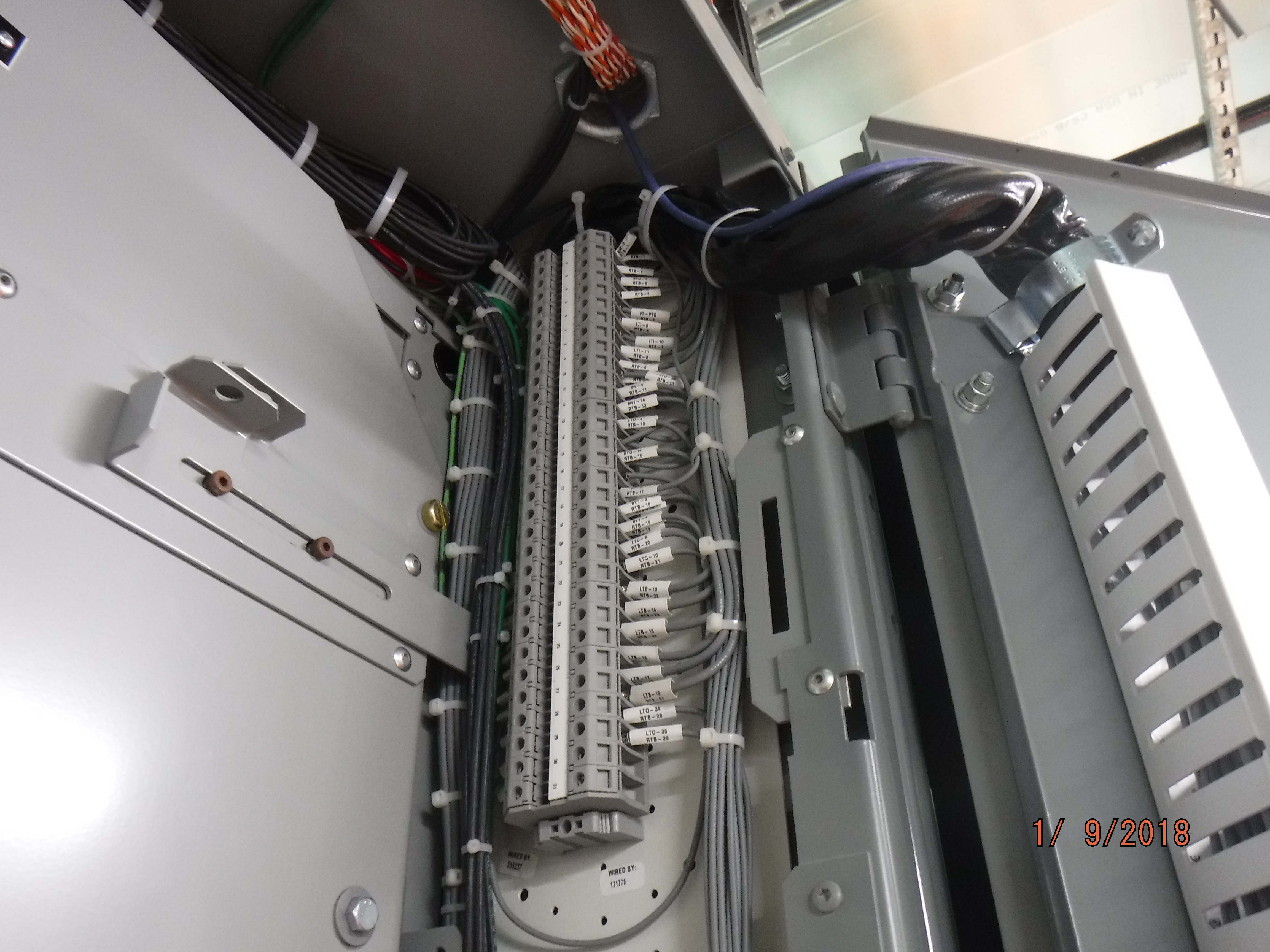
Ask whether the conductor material, class, size, preparation, clamp, mounting foot, bridge system, and approval all match. Physical fit proves only physical fit.
Ask which IEC, UL, or other rating applies to the target market and conductor. Values on the same datasheet can differ because the test and use conditions differ.
Ask whether the exact model permits that conductor combination. If it does not, use an approved multi-conductor or distribution arrangement.
Ask for the installation sheet. Too much exposed copper, trapped insulation, loose strands, under-tightening, and over-tightening can all create defects.
Ask whether the term describes wire termination or a removable connector interface. A product can be pluggable and still use a screw or spring to hold the wire.
Ask for the terminal function. A normal feed-through block carries current through its internal link; a PE block may intentionally bond to a correctly grounded rail.
Ask for enclosure- or assembly-level ingress, condensation, UV, corrosion, pollution, and temperature evidence. The plastic body alone is not an outdoor rating.
Ask for the exact certificate or recognition file and model coverage. CE marking and RoHS declarations do not replace a model-level safety evaluation.
The application tells you which circuit functions, conductor ranges, accessories, and evidence matter. These examples show common roles, not universal approval for every environment.
Feed-through, PE, fuse, disconnect, and multi-level blocks can organize power, control, measurement, and field wiring. Markers, bridges, end stops, and test points are often part of the same terminal-strip plan.
Components for panel builders →Compact multi-level or sensor/actuator terminals can group signals and supply potentials. The designer must prevent accidental commoning and keep the drawing, bridges, and markers aligned.
Automation and machine control →A stable terminal-strip layout helps connect the approved model, accessory set, label scheme, inspection focus, and packaging to repeat production.
Support for equipment manufacturers →Terminal blocks form interfaces between panel wiring and field circuits. Enclosure, maintenance access, conductor schedule, and local equipment requirements shape the final choice.
Terminal points can organize controller signals, status contacts, sensing, auxiliaries, and field connections. They do not replace the transfer device, protective equipment, or system design.
PCB terminal blocks bring field conductors onto a board. Pluggable versions can separate equipment assembly from field wiring when the plug, header, coding, and ratings all match.
Standards define test scopes and product requirements. They do not give every terminal block the maximum value in the standard's scope, and they do not replace the end-product evaluation.
Read the exact model's rating table, certificate or recognition record, instructions, and Conditions of Acceptability. Also check whether the product function belongs to a different standard part, such as a protective-conductor or fuse terminal.
The fourth edition covers support-mounted screw-type and screwless terminal blocks. It also covers the test-disconnect blocks described in its Annex D, primarily for industrial or similar use. Its scope extends to stated conductor sizes and voltages, but those scope limits are not the rating of every product.
View the official IEC scopeIEC addresses protective-conductor terminal blocks and fuse terminal blocks in separate parts. This is one reason a general “IEC terminal block” claim is not enough; the exact function and model coverage matter.
IEC 60947-7-2 · IEC 60947-7-3The current scope covers terminal blocks rated 1,500 V or less, while an individual model may be rated much lower. UL also states that compliance does not, by itself, prove suitability in every end product or service condition.
View the official UL 1059 scopeA recognized component is evaluated for use within a larger product under stated conditions. Confirm the exact file, model, ratings, and installation conditions, then complete the required end-product evaluation.
Read UL's component-recognition explanationSENTOP supports component matching around your panel and project. Send a model, photo, drawing, sample, or terminal-strip BOM together with the electrical and conductor data. The goal is to connect the proposed part, accessories, labels, documents, quantity, and delivery needs to one clear request.
This page explains the foundation. Move to the focused guide that matches your task instead of forcing every detail into one beginner article.
Use these answers as a starting point. The exact datasheet and equipment rules still decide whether a model is suitable.
A terminal block holds conductors in defined terminal points and provides the intended electrical and mechanical connection. A feed-through block joins one conductor to another through a conductive link. Other models may distribute one potential, connect protective earth, hold a fuse, or provide a test or disconnect point.
No. A standard terminal block is a connection path, not a regulator. It does not raise, reduce, or control voltage or current. Its voltage and current markings are operating limits under stated conditions. A fuse terminal can add overcurrent protection only when the approved fuse and complete assembly are correctly selected.
Only the number and conductor combination approved for that exact model. Never assume that two wires can share one clamping point because they physically fit. Use an approved multi-conductor, distribution, or bridged arrangement when several conductors must share one potential.
They can perform similar circuit functions, but they hold the conductor in different ways. Compare conductor type and preparation, ratings, space, vibration, production method, service instructions, and approvals. Push-in does not mean every conductor can be inserted directly without a tool.
No. Many industrial terminal blocks mount on a DIN rail. Other products mount directly to a panel or chassis, solder to a printed circuit board, or use a pluggable header. Confirm the rail profile, hole pattern, PCB footprint, or mating interface from the exact drawing.
Many designs allow conductors to be removed and reconnected, but the approved method and any cycle limit are product-specific. Inspect the terminal and conductor, use the correct release method, and replace damaged or out-of-spec parts. Do not promise unlimited reuse.
An open terminal block is not automatically weatherproof. Outdoor use must be evaluated with the enclosure or complete assembly for ingress, condensation, UV exposure, corrosion, pollution, temperature, and spacing. Use the product and enclosure evidence for the actual installation.
Send the circuit function, voltage, current, conductor material and size, conductor class and preparation, conductors per point, poles, mounting, dimensions, and environment. Also send the target market, required documents, quantity, destination, and any existing model, photo, drawing, sample, or BOM.
Send the circuit function, conductor, ratings, mounting, environment, target market, quantity, destination, and document needs. SENTOP can help organize the next component-matching step.
